KOBE SBD370 User manual

COMBINATION
BELT/DISC SANDER
MODEL SBD370
ORDER CODE KBE-271-4140K
OPER ATOR’S MANUAL
Please retain this information for future reference.
WARNING:
THE SAFETY INFORMATION
GIVEN INSIDE MUST BE READ AND
UNDERSTOOD BY ANY PERSON
USING, INSTALLING, REPAIRING
OR MAINTAINING THIS PRODUCT.
ALWAYS WEAR
APPROPRIATE
PERSONAL
PROTECTIVE
EQUIPMENT.
DECLARATION OF CONFORMITY
We hereby certify that the Kobe
Combination Belt/Disc Sander SBD370
comply with all the relevant provisions of the following European Community Directives:
Electromagnetic Compatibility 204/108/EC, Low Voltage 2006/95/EC, Machinery 2006/42/EC,
Standards Applied:
EN 55014-1: 2006/A2:2002, EN 55014-2: 1997/A1:2001,
EN 61000-3-2: 2006 EN 61000-3-3:1995/+A1: 2001/+A2: 2005,
EN61029-1: 2000+A11: 2003+A12: 2003, EN61029-1: 2009
Official Agent:
THE KENNEDY GROUP Ltd
Wigston Works, Leicester, England.
ISO 9001 REGISTERED COMPANY
Signed:
Date: 31St January 2011 Name: Martin Cooke Position: Director, The Kennedy Group Ltd.
© The Kennedy Group Ltd. 01/11
Kobe Tools continually strives to improve its products. Specifications may change without prior notice.
KOBE PRODUCTS carry a one years manufacturers warranty.
KOBE PRODUCTS are designed & produced to the highest standards & specifications
KOBE PRODUCTS are fully guaranteed against faulty materials & workmanship
Should they be found to be defective, they will either be repaired or replaced
free of charge (fair wear and tear and/or misuse excepted).
This does not affect your legal rights.
Please retain supplier invoice as proof of purchase.
QUALITY GUARANTEE & WARRANTY
KOBE TOOLS Official Agents:
JAPAN: MIKI TOOL TRADING CO. MIKI CITY, JAPAN.
EUROPE, MIDDLE EAST, AMERICA & AFRICA: THE KENNEDY GROUP LTD, WIGSTON, ENGLAND.
230V AC
1/2
HP
MOTOR
370W
KBE-271-4140K_Instructions.qxd 01/02/2011 09:52 Page 1

2 11
SERVICE & REPAIR
KOBE
INDUSTRIAL
POWER TOOLS
You have purchased a quality industrial product that is designed for high performance
and long service life. If correct use, safety and maintenance procedures are observed
this machine will last for many years.
SAFETY INSTRUCTIONS
KOBE INDUSTRIAL POWER TOOLS
have been specifically designed to help you work SAFELY
and EFFICIENTLY. Your care and good judgement are the best protection against injury, but always ensure
that the appropriate safety equipment is worn. All possible hazards cannot be covered here, but the most
important ones have been highlighted.
PERSONAL PROTECTION
Always wear eye protection that complies with a recognised standard (CSA or ANSI).
Wear a mask or respirator when dust is generated.
Some dust created by power sanding contains chemicals that may cause cancer, birth defects or other
harm. Some examples of these chemicals are: lead from lead-based paint, and arsenic and chromium
from chemically treated lumber. To reduce exposure to these chemicals, work in a well-ventilated area;
use approved safety equipment; and use dust masks that are specially designed to filter out
microscopic particles.
Keep bystanders out of the work area while operating the tool.
ALERTNESS
Always stay alert, watch what you are doing and use common sense when operating this tool.
Never operate the sander when tired or under the influence of alcohol or prescription/non-prescription
drugs.
Do not wear loose clothing or jewellery. Keep hair tied back.
ELECTROCUTION
Always keep dry. Do not use in rain, snow or near water.
Always place the Sander on a non conductive surface.
Always switch the power off prior to plugging in the tool.
Grounded tools must be plugged into an outlet that has been properly installed and grounded in
accordance with all local legislation. Never remove the grounding prong from the plug or modify it in any
way. Do not use adaptor plugs. If in doubt as to whether the outlet is properly grounded, consult a
qualified electrician.
Never touch with wet hands.
SYMBOLS USED ON THE SANDER
Warning Read the
Operator’s Manual
KOBE
INDUSTRIAL
POWER TOOLS
THE ENVIRONMENT
Always dispose of unwanted tools, accessories and packaging materials in an environmentally
friendly manner.
A comprehensive repair and
service facility is available
through your local Kobe agent for
all your electric tools.
This sander requires little
maintenance other than clean or
vacuum dust any from around the
motor housing, extraction port
and other sander parts.
Dress sanding surfaces and replace discs/belts as required - a worn belt or disc leads to inefficiency and
extra wear on the machine due to increased pressure required to do the job.
Continued on page 3
KOBE
INDUSTRIAL
POWER TOOLS
ITEMS FROM THE KOBE RANGE
For EU and EEA countries only.
In observance of European Directive 2002/96/EC on Waste Electrical and Electronic Equipment
(WEEE) and its implementation in accordance with national law, electrical goods that have reached
the end of their life must be collected separately and returned to an environmentally compatible
recycling facility.
Do not dispose of electrical goods with domestic waste materials as inappropriate disposal may
cause potential hazards to the environment and human health.
For further information, please contact your local authority or the retailer from whom you purchased
the product.
This product does not contain any restricted substances in concentrations and applications which
are banned by the European RoHS Directive.
KBE-271-4140K_Instructions.qxd 01/02/2011 09:52 Page 2

FAULT
Sanding grains easily rub off
belt/disc.
Deep sanding grooves or
scars in the workpiece.
Sanding surface clogs
quickly.
Burns on workpiece
Motor will not start.
Motor will not start – fuses
or circuit breaker tripping or
blowing.
Motor overheats
Motor stalls (resulting in
blown fuses or tripped
circuit breaker)
Machine slows when
operating.
Machine vibrates
excessively.
Workpiece frequently gets
pulled out of operator’s
hands.
Workpiece lifts up from the
sanding disc/table.
POSSIBLE CAUSE
1. Incorrect storage.
2. Belt/disc has been
damaged or folded.
1. Sanding Belt grit is too
coarse.
2. Workpiece has been sanded
across the grain.
3. Too much force applied to
the workpiece.
4. Workpiece held against the
belt/disc for too long.
1. Too much pressure against
the belt/disc.
2. Sanding softwood.
1. Using a sanding grit that is
too fine.
2. Using too much pressure
3. Work held still for too long.
1. Low voltage.
2. Open circuit in motor or
loose connections.
3. Blown fuse or breaker.
1. Short circuit in line, cord or
plug.
2. Short circuit in motor or
loose connections.
3. Incorrect fuses or circuit
breakers in power line.
1. Motor overloaded.
2. Extension cord too long and
or insufficient gauge (weight)
1. Short circuit in motor or
loose connections.
2. Low voltage.
3. Incorrect fuses or circuit
breakers in power line.
4. Motor overloaded
1. Feed rate too great.
2. Undersized circuit or use of
undersized extension cord.
1. Incorrect motor mounting.
2. Incorrect sanding belt tension.
3. Weak or broken tension spring.
4. Idler roller is too loose.
5. Broken/defective sanding
accessories.
1. Not supporting the workpiece
against the stop.
2. Attempting to sand (unaided)
a workpiece that is too small
1. Sanding on the “up” side of
the wheel.
10 3
SAFETY INSTRUCTIONS Continued
KOBE
INDUSTRIAL
POWER TOOLS
TROUBLESHOOTING
SOLUTION
1. Store away from extreme heat/dry temperature.
2. Store flat – do not bend or fold.
1. Use a finer grit sanding accessory.
2. Sand with the grain of the wood.
3. Reduce pressure on workpiece.
4. Keep workpiece moving while sanding on the sanding
accessory.
1. Reduce pressure on workpiece while sanding.
2. Use different stock, different sanding accessories, or
accept that this will happen and plan on cleaning and
replacing belts/discs frequently.
1. Use a coarser grit sanding accessory
2. Reduce pressure on workpiece while sanding.
3. Do not keep workpiece in one place for too long.
1. Check power source for proper voltage.
2. Inspect all lead connections on motor for loose or
open connections.
3. Improper match between tool and circuit, fuse or
breaker.
1. Inspect cord or plug for damaged insulation and
shorted wires.
2. Inspect all connections on motor for loose or shorted
terminals and/or worn insulation.
3. Install correct fuses or circuit breakers or switch tool
to an appropriately sized circuit.
1. Reduce load on motor (pressure on object being sanded)
2. Use an extension of the appropriate gauge and
length or plug tool directly into socket outlet.
1. Inspect connections on motor for loose or shorted
terminals or worn insulations.
2. Correct low voltage conditions for example improper
extension cord length or gauge.
3. Install correct fuses or circuit breakers or plug into an
appropriate circuit, matched to an appropriate circuit
breaker.
4. Reduce the load on the motor.
1. Reduce the rate at which the workpiece is fed into
the working area of the tool.
2. Ensure circuit wires or extension cords are proper
gauge, or eliminate use of extension cords.
1. Have motor mountings inspected by a service
technician.
2. Adjust tension adjustment knob. Follow belt
tensioning/tracking instructions in this manual.
3. Have tension spring replaced by service technician.
4. Have service technician adjust idler drum.
5. Replace sanding belt/disc.
1. Use the platen (back stop) or mitre gauge to support
the workpiece.
2. Use another hand tool or jig to grasp or hold the
workpiece.
1. Sand on right side of sanding disc (as operator faces
the disc).
Repairs must be performed in a dirt-free environment by a qualified person who is familiar with this type
of equipment.
GENERAL OPERATING HAZARDS
Always ensure that the work area is clear of any flammable materials, liquids or gasses, because the
use of this tool may create sparks.
Keep guards in place and working properly.
Keep hands clear of sanding areas.
Ensure sanding belt runs in the proper direction. Sanding belt must travel down at the front of the
machine.
Ensure sanding belt is tracking properly so that it does not come off the pulleys.
Unplug from power supply before adjusting or servicing.
Always use only accessories that are recommended by the manufacturer for your model.
Ensure sanding belt or disc is not torn or loose.
Hold workpiece firmly while sanding.
Firmly support workpiece with mitre gauge, backstop, jig or worktable when sanding with the belt.
AVOID kickback by sanding in accordance with directional arrows. Sand on downward side of disc only!
DO NOT attempt to hold pieces of material that are too small to be safely supported by hand.
Use special jigs or hand tools.
Remove scrap pieces and other loose objects from the belt and disc tables before turning the
machine on.
When sanding metal, move the metal across the belt or disc and cool it when it becomes hot.
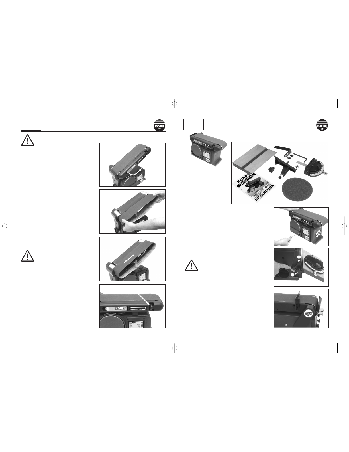
WARNING! Do not operate your belt & disc sander until it is completely assembled and installed
according to the instructions.
Service on these tools should only be performed by an authorized, qualified technician.
SAVE THESE INSTRUCTIONS.
WORKPLACE HAZARDS
Always comply with Health & Safety regulations.
Always be aware of power leads. Slip/Trip/Fall is a major cause of serious injury or death.
Yellow & Green = Earth wire
Cable restraint
UK
ONLY
Brown = Live wire
Blue = Neutral wire
PLUG FITTING
A moulded UK 3 pin plug with ASTA/BS approval is already fitted for
your safety. If it becomes damaged, and needs replacing, cut off the
plug and prepare the wires. Use the following instructions:
a) Connect the GREEN/YELLOW earth wire to the earth terminal
marked either ‘ E’ or with the earth symbol‘ ’.
b) Connect the BROWN live wire to the live terminal marked ‘ L’ or
coloured black or blue.
c) Connect the BLUE neutral wire to the neutral terminal marked ‘ N’
or coloured red or brown.
d) After wiring, check there are no bare wires, that all wires have been
correctly connected, that the cable external insulation extends
beyond the cable restraint and that the restraint is tight.
d) The power cord and/or the plug should only be replaced by a
qualified electrician or professional technician
KBE-271-4140K_Instructions.qxd 01/02/2011 09:52 Page 3

4 9
KOBE
INDUSTRIAL
POWER TOOLS
IDENTIFICATION
COMPONENTS
Drive belt
cover
Belt sanding
area
Sanding
stop
Drive drum
Belt tracking
adjustment knob
Idler drum
Belt tensioning
lever
Dust port
(not visible)
see
Fig.4c
Base
fixing
flange
NO VOLT
On/Off switch
Disc
sanding area
Sanding
table
Mitring
attachment
Table adjuster
(not visible)
see
Fig.4b
MODEL NUMBER: ................................................................................................................. SBD370
MOTOR (Induction): .......................................................................................... 230V AC, 50Hz, 370W
MOTOR SPEED (No load): ................................................................................................... 2850RPM
DISC SIZE (Diameter): ........................................................................................................... 150mm
DISC TYPE: .............................................................................. PSA type (Pressure sensitive adhesive)
BELT SIZE: ...................................................................................................................100 x 914mm
BELT SPEED: .................................................................................................. 580m/min (1900 SFM)
BELT TILT: .............................................................................................................................. 0 - 90°
WORK TABLE TILT: .................................................................................................................. 0 - 45°
SOUND PRESSURE (LPA): ..................................................................................................... 79.9dBA
SOUND POWER (LWA): ......................................................................................................... 91.1dBA
NET DIMENSIONS: .............................................. 285 - 620 (H) with belt vertical x 450(W) x 365(D)mm
NET WEIGHT: ......................................................................................................................... 18.6kg
Supplied with: 1 x 150mm P80 sanding disc
1 x 100 x 914mm A80 sanding belt
SPECIFICATIONS
KOBE
INDUSTRIAL
POWER TOOLS
Fig. 1
SANDING DISC
Note: Hook and loop sanding discs cannot be used with this machine.
Follow steps 1 to 8, Figs.10-16
1. Remove the mitre gauge, work table & disc guard.
2. Remove the self adhesive sanding disc from the plate.
3. Clean off any adhesive remaining on the plate with a
suitable cleaning spirit.
4. Spread your thumb and middle finger on the edge of
the plate as a guide for placing the disc.
5. Carefully align the edge of the disc with the edge of the
plate before pressing it firmly in place.
6. Refit the disc guard
7. Refit the Work table, making sure the gap between the
table and disc is no more than 1.6mm when horizontal.
8. Replace the mitre gauge.
KOBE
INDUSTRIAL
POWER TOOLS
CHANGING CONSUMABLES
Fig. 10
Fig. 14
Fig. 12
Fig. 16
Fig. 13
Fig. 11
Fig. 15
KBE-271-4140K_Instructions.qxd 01/02/2011 09:52 Page 4

Your sander has been shipped assembled with the exception of
the sanding disc, disc guard, mitre gauge, sanding stop, and
worktable. Carefully remove all parts from the box.
Do not discard the packaging until the parts have been checked
against the list in Fig.2 and the sander has been fully
assembled and tested to make sure it is working correctly.
Unless you need to move the sander regularly it is always best
to securely mount it on a workbench using hexagon bolts,
washers and locking nuts (not supplied) to fix it using the holes
in the base mounting flanges.
ASSEMBLY
WARNING
Always ensure the sander is
unplugged before attempting assembly, installation
or changing parts or accessories.
1. Remove the disc guard as shown in Fig.3.
2. Remove the backing paper from the sanding disc (10) and
carefully place centrally on the sanding plate, aligning with
edges and making sure it is pressed firmly into place all
over, leaving no loose edges.
3. Replace the disc guard as shown in Fig. 3.
4. Fix the worktable (2) to the support arm (3) using the
Hex. bolts and washers (4). Attach the work table assembly
to the main body of the sander by (a) placing the spigot
of the support arm into the hole in the body and (b) screw
the fixing screw into the threaded hole next to it to secure
it at the required angle a shown in Fig.4.
5. Attach the sanding stop (6) to the rear of the machine using
the M8 Hex, head cap screws (7) as shown in Fig.5. Loosely
attach with the minimum of clearance above the sanding
belt then tighten with the hexagon key supplied (8).
8 5
KOBE
INDUSTRIAL
POWER TOOLS
UNPACKING/ASSEMBLY
1. Sander
2. Work table
3. Work table support arm
4. M6 x 12 Hexagon bolts
& washers (3)
5. Work table fixing screw
6. Sanding stop
7. M8 x 16 Hexagon cap
screws (2)
8. M8 Hexagon key
9. Mitre Gauge
10. Sanding disc 150mm 80grit psa
type (pressure sensitive adhesive)
11. Operator’s Manual
2.
3.
4.
5.
6.
7.
8.
9.
10.
Fig. 2
Fig. 3
Fig. 4
a
b
Fig. 5
11.
1.
UNPACKING
WARNING
Always ensure the sander is unplugged before attempting assembly,
installation or changing parts or accessories.
SANDING BELT
The belt will wear at different rates depending on the
type of material being sanded and the pressure being
applied to the workpiece.
1. Slide the tensioner to the right to release belt tension
as in Fig. 6.
2. Remove the worn belt from the drive mechanism as
shown in Fig. 7, taking note of the direction of travel
of the belt (towards the left hand end of the machine
denoted by the dust extraction port).
3. Place the new belt in position over the drums as
shown in Fig.8, with the edge of the belt aligned with
the rear of the drums then release the tensioner to
grip the belt.
4. Before using, check the tracking as described in
“Belt Tracking“ and adjust as necessary.
BELT TRACKING
The belt-tracking adjustment is set at the factory so that
the abrasive belt will run true on the drums. If however,
the belt should track to one side or the other, an
adjustment can be made by turning the tracking knob,
which is located on the top right hand side of the front of
the machine Fig. 9. Turn the knob clockwise to make the
belt track onto the back of the machine or anti clockwise
to track towards the front of the machine.
WARNING
Be careful if turning anti
clockwise as this could make the belt
track off the side of the machine and
possibly cause personal injury.
To properly track the sanding belt:
1. Plug in the sander.
2. Turn the power switch on and then off, taking note of
whether the belt moves in its track to one side or the
other or stays with it’s edge against the rear of the
drums.
3. If it does not move then the tracking is set correctly.
4. If the belt moves towards the front of the machine,
turn the tracking knob clockwise a 1/4turn.
5. Turn the power switch on and then off again, taking
note of any belt movement.
6. Readjust the tracking knob another 1/4turn, as
necessary.
KOBE
INDUSTRIAL
POWER TOOLS
CHANGING CONSUMABLES
Fig. 6
Fig. 8
Fig. 7
Fig. 9
KBE-271-4140K_Instructions.qxd 01/02/2011 09:52 Page 5

6 7
KOBE
INDUSTRIAL
POWER TOOLS
OPERATING INSTRUCTIONS
WARNING
Some dust created by power sanding contains chemicals that may cause
cancer, birth defects or other harm. Some examples of these chemicals are: lead from lead-
based paint, and arsenic and chromium from chemically treated timber.
DUST EXTRACTION
Sanding operations are inherently dusty. To reduce the amount of dust pervading the air, the
sander has a dust extraction port which is 57mm (21/4”) in diameter which can easily be
connected to a dust collection system. It is strongly recommended that users employ a dust
collection system when using this sander.
Use of a mask or respirator is still required even
when a dust collection system is in use.
ON/OFF SWITCH
The ON/OFF switch is situated bottom right on the front of the
machine. The buttons are marked with international convention
being green for on and red for off. The green “ON” button is
recessed into the switch making it difficult to accidentally switch
the machine on, whereas the red “OFF” button stands out from
the switch making it easy to locate and press should emergency
require it.
NO VOLT RELEASE SWITCH
In the event of a power failure, the NO VOLT RELEASE SWITCH
automatically reverts to the OFF position. This eliminates
accidental start up of the machine when mains power is restored.
BELT SANDING – HORIZONTAL or VERTICAL
This sander can be used in vertical or horizontal mode.
To change the position of the belt sanding bed:
1. Using the Hexagon Key supplied, loosen the 6m cap screw
which clamps the drive mechanism as shown in Fig.17.
2. Raise the belt sanding bed as shown in Fig. 18.
3. With the belt sanding bed in the vertical position as shown
in Fig.19, tighten the cap screw in order to lock the bed in
place as shown in Fig 20.
Note: When sanding long workpieces, with the belt in the vertical
position, place the workpiece on the sanding stop and work
evenly across the belt. Fig. 21
Fig. 17
Fig. 18
Fig. 19
Fig. 20
KOBE
INDUSTRIAL
POWER TOOLS
OPERATING INSTRUCTIONS
BELT SANDING – HORIZONTAL
When sanding flat, broad surfaces on the belt sander, hold the
workpiece firmly but lightly onto the surface of the belt and
against the sanding stop, Fig.22 keeping fingers away from the
belt. Apply only enough pressure to remove material from the
workpiece. Too much pressure will cause undue load on the
machine’s motor, create heat on the bed and shorten the life
of the belt.
Note: Use extra caution when sanding very thin pieces and when
sanding long pieces, remove the sanding stop.
BELT SANDING – CURVED PIECES
When sanding inside curves on the belt sander, always sand on
the idler drum (right hand) end of the bed Fig.23. Hold the
workpiece firmly, keeping fingers away from the sanding belt.
Keep the curve pressed firmly against the idler drum, moving the
work evenly back and forth across the drum.
DISC SANDING – CURVED PIECES
When sanding outside curves on the disc sander, remove the
mitre gauge and work with the workpiece flat on the table. The
point of contact between the disc and the workpiece should
always be on the left hand side of the disc so that it is in the
downward motion, decreasing the chance of wood splintering
away from the main body of the workpiece.
DISC SANDING – MITRED ANGLES
To sand mitred angles on the disc sander, set the mitre gauge
to the required angle (up to 60°to the left or right) and tighten
the locking knob as shown in Fig.24.
DISC SANDING – COMPOUND MITRES
A compound angle can be achieved by setting the angle of the
work table to the horizontal plane first (up to 45°to the
horizontal) and then setting the angle of the mitre gauge (up to
60°to the left or right) to the disc as shown in Fig.25.
DISC SANDING – SMALL END GRAINS
Use of the sliding mitre gauge is recommended for sanding
small end grain surfaces on the sanding disc.
Note: Always move the workpiece across the sanding disc from
left to right holding the workpiece tightly onto the surface of the
work table.
Fig. 21
Fig. 22
Fig. 23
Fig. 24
Fig. 25
KBE-271-4140K_Instructions.qxd 01/02/2011 09:52 Page 6
Other manuals for SBD370
1
Table of contents
Other KOBE Sander manuals
Popular Sander manuals by other brands

Dynabrade
Dynabrade 52400 Operating, maintenance and safety instructions

Jet
Jet 708599 Operating instructions and parts manual

Ryobi
Ryobi CRO1800 Operator's manual

Porter-Cable
Porter-Cable 7800-XE instruction manual

Dynabrade
Dynabrade Mini-Dynafile II 15003 Safety, operation and maintenance

Makita
Makita DBO140 instruction manual