Kobelt 2009 Instruction Manual

Kobelt Manufacturing Co. Ltd.
2009 Control Head
Owner’s Operation, Installation &
Maintenance Manual

2009 Control Head Kobelt Manufacturing Co. Ltd.
Rev A mnl_2009.docx 2 of 20
NOTES:
RECORD DATA BEFORE INSTALLATION FOR FUTURE REFERENCE
Model #:
Serial #:
Date of Purchase:
Date of Installation:

2009 Control Head Kobelt Manufacturing Co. Ltd.
Rev A mnl_2009.docx 3 of 20
Table of Contents
1Introduction ..................................................................................................................4
1.1 Contact ...................................................................................................................................... 4
1.2 Safety......................................................................................................................................... 4
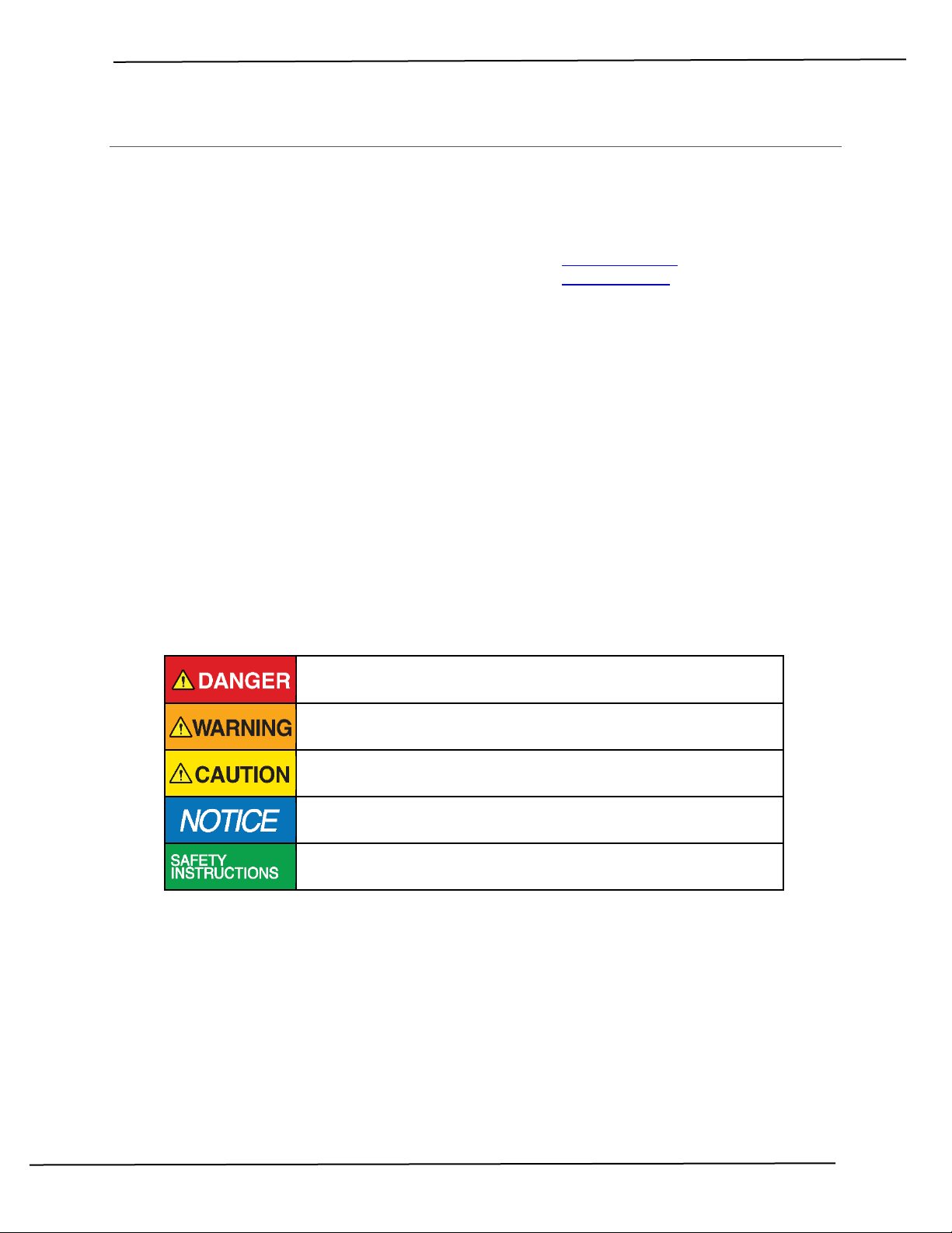
1.2.1 Safety Alerts .......................................................................................................................... 4
1.2.2 Notice to Installer.................................................................................................................. 4
1.2.3 Product Hazards .................................................................................................................... 5
2Product Description .......................................................................................................6
2.1 Overview.................................................................................................................................... 6
2.2 Technical Data ........................................................................................................................... 7
2.3 Model Code Key......................................................................................................................... 7
3Installation ....................................................................................................................8
3.1 Mechanical ................................................................................................................................ 8
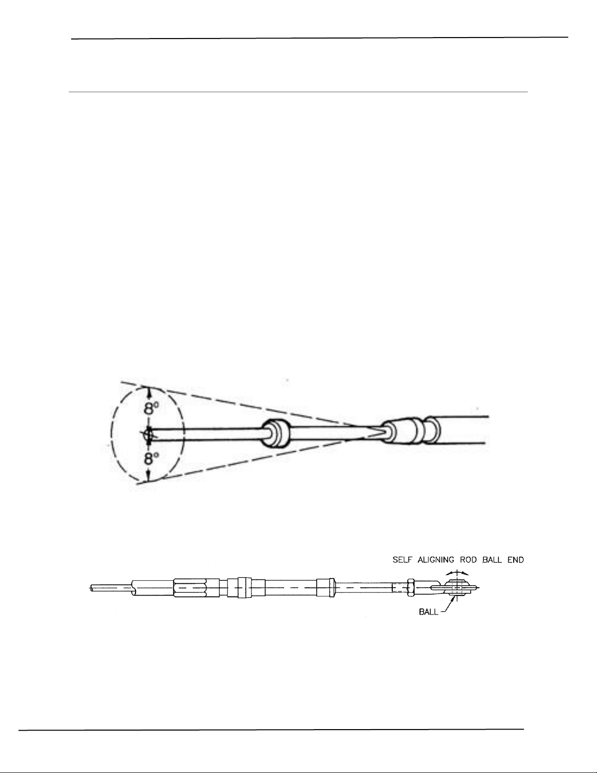
3.2 Control Cable............................................................................................................................. 8
3.2.1 Hardware............................................................................................................................... 8
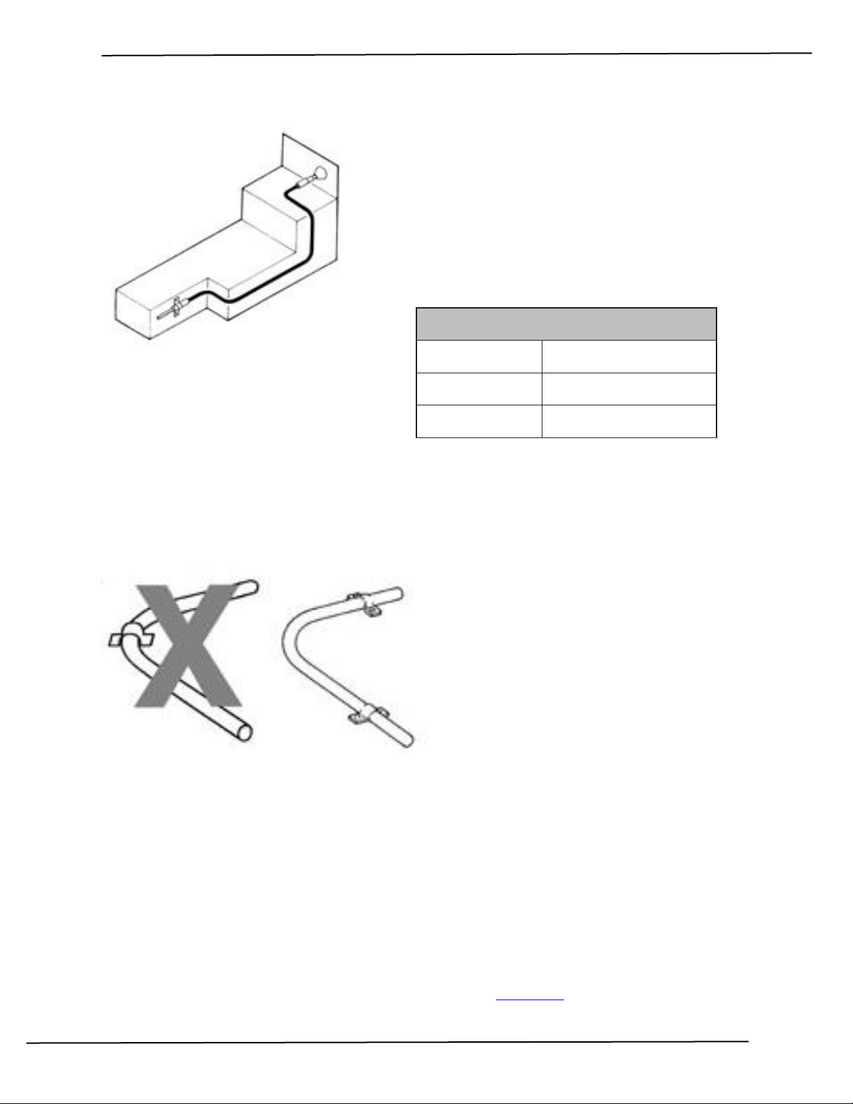
3.2.2 Cable Routing ........................................................................................................................ 9
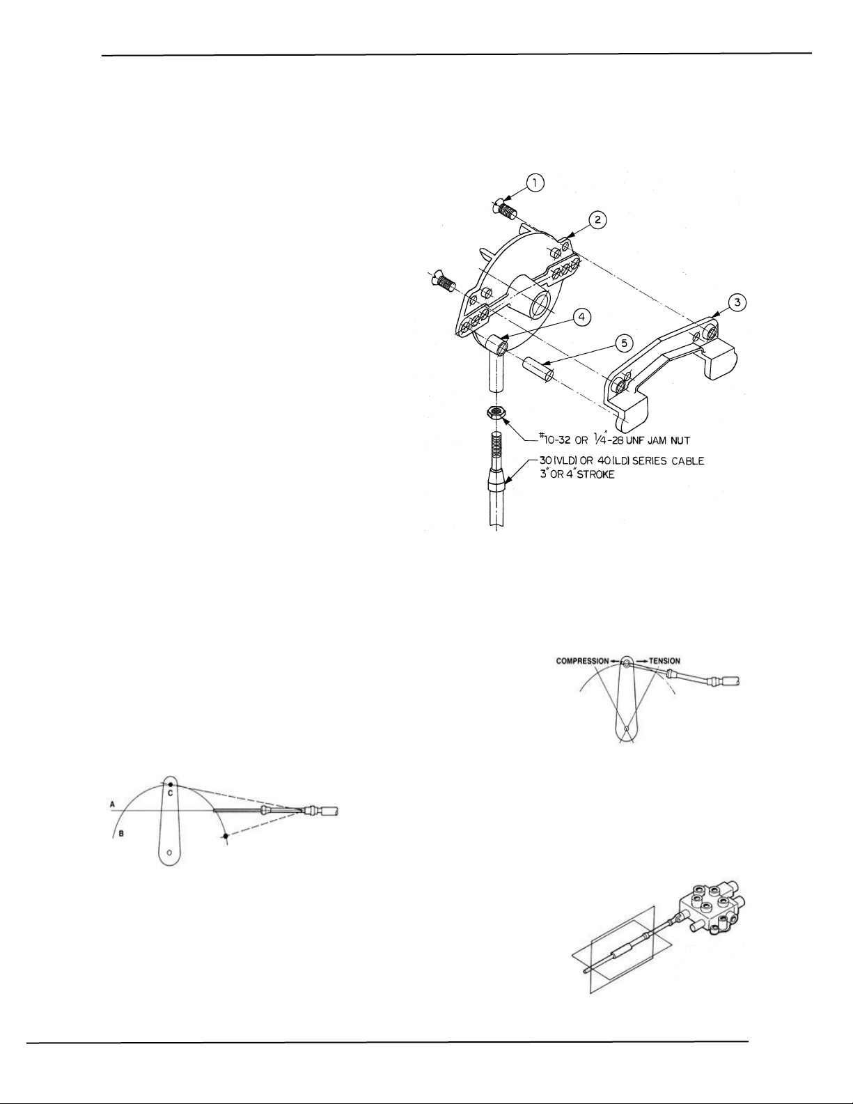
3.2.3 Control Head Connection ...................................................................................................... 9
3.2.4 Actuator End Connection .................................................................................................... 10
3.3 Electrical .................................................................................................................................. 11
4Commissioning ............................................................................................................12
4.1 Inspection................................................................................................................................ 12
4.2 Functional Test ........................................................................................................................ 12
5Maintenance ...............................................................................................................13
5.1 Preventative Maintenance ...................................................................................................... 13
5.2 Inspection................................................................................................................................ 13
5.3 Recommended Spare Parts and Kits........................................................................................ 13
5.3.1 Accessories.......................................................................................................................... 13
5.4 Troubleshooting ...................................................................................................................... 14
6Warranty.....................................................................................................................15
7Appendix A: Installation Dimensions ............................................................................16
8Appendix B: Parts List ..................................................................................................17
9Appendix C: Installation Cut-out Template....................................................................19

2009 Control Head Kobelt Manufacturing Co. Ltd.
Rev A mnl_2009.docx 4 of 20
1INTRODUCTION
1.1 CONTACT
Kobelt Manufacturing Co. Ltd.
8238 129th Street
Surrey, British Columbia
Canada, V3W 0A6
Sales Tel:
Fax:
Email:
Website:
This document is intended to clearly present comprehensive product data and provide technical
information to assist the end user in design applications. Kobelt reserves the right, without notice, to
change the design, or construction, of any products and to discontinue or limit distribution of any
products. Kobelt also reserves the right to change, or update, without notice, any technical information
contained within this document.
Kobelt recommends that customers visit our website to check for updates to this Manual. Once a
product has been selected for use, it should be tested by the user to ensure proper function in all
possible applications. For further instructions, please contact our distributors or visit our website.
1.2 SAFETY
1.2.1 Safety Alerts
Throughout this manual, the following symbols, and their accompanying explanation, are used to alert
the user to special instructions concerning a service or operation that may be hazardous if performed
incorrectly or carelessly. The associated risk levels are stated below.
This symbol indicates an imminently hazardous situation which, if not
avoided, will result in death or serious injury.
This symbol indicates a potentially hazardous situation which, if not
avoided, could result in death or serious injury.
This symbol indicates a hazardous situation, which if not avoided, could
result in minor or moderate injury.
This symbol informs the reader of events not related to personal injury
but which there is a risk of damage to property or equipment.
This symbol informs the reader of safety-related instructions or
procedures.
1.2.2 Notice to Installer
Disregarding the following safety measures can result in an accident causing severe injury to personnel
and damage to material assets.
•Only use the product as directed in this manual.
•Never put the product into service if there is evidence of visible damage.
•Never put the product into service before fully completing installation and commissioning.
•Do not carry out any modifications to the product.

2009 Control Head Kobelt Manufacturing Co. Ltd.
Rev A mnl_2009.docx 5 of 20
•Only use authentic Kobelt spare parts.
•Observe all local regulations, directives and laws during the installation of this product.
•All installation, commissioning, and maintenance work must only be conducted by qualified
personnel. (For the purpose of this manual, qualified personnel are persons who are familiar with
the assembly, installation, commissioning, and operation of the product and who have the
qualifications necessary for their occupation.)
•Observe all specifications in this manual. If these guidelines are not followed and damage occurs,
the warranty will be voided.
1.2.3 Product Hazards
Equipment Starts Automatically:
Vessel propulsion may activate suddenly while servicing
this product, causing bodily harm. Ensure that all power
sources are locked out prior to performing work.
Pinch Points:
The 2009 control head contains pinch points, which can
cause bodily harm. Ensure that hands and fingers
remain clear of the pinch points when performing work.

2009 Control Head Kobelt Manufacturing Co. Ltd.
Rev A mnl_2009.docx 6 of 20
2PRODUCT DESCRIPTION
2.1 OVERVIEW
The Kobelt 2009 push-pull control head can be configured to provide either;
a) twin-engine throttle control with friction hold,
b) Twin-engine clutch control with neutral, ahead & astern detents, or,
c) Single engine clutch and throttle control
For twin engine throttle control or single engine clutch control, the 2009 control head can also act as a
relay station for multi-station set-ups.
The 2009 is available in a combination of black and chrome, all black, or all polished chrome to suit your
appearance preference. Accessories, such as neutral safety switch kits or throttle extension kits can be
ordered with the units or as after market parts.

2009 Control Head Kobelt Manufacturing Co. Ltd.
Rev A mnl_2009.docx 7 of 20
2.2 TECHNICAL DATA
Handle Travel:
•Neutral: 0oDetented
•Clutch engage: +/- 30oDetented
•Full throttle: +/- 60o-
Stroke:1
•Pin position:
1
2
3
•Cable stroke:
2.18 in
[55 mm]
2.76 in
[70 mm]
3.34 in
[85 mm]
Force Output:2
•Extension: 125 lbf [556 N]
•Retraction: 230 lbf [1024 N]
Lever ratio: 2.7:1
Ambient Temperature: -40°F…+140°F [-40 °C… + 60 °C]
Weight: 5.4 lbs [2.5 kg]
1) Stroke from TDC is half of value shown.
2) Force output limited by rating of the cable. Values shown are for 40 series cable.
2.3 MODEL CODE KEY
The 2009 control head can be configured in several different ways. Below is a key defining the letter
code options:
1) Neutral safety switch must have a detented handle.
2) Prevents shifting at engine speeds above idle.
3) One red (throttle / friction) and one black (clutch / detented)

2009 Control Head Kobelt Manufacturing Co. Ltd.
Rev A mnl_2009.docx 8 of 20
3INSTALLATION
3.1 MECHANICAL
The control head must be mounted on a flat surface strong and stiff enough to withstand the cable
forces listed in the technical section without excessive flexing. Choose a location that has sufficient
room for the handles in both extreme positions.
The control head is equipped with (4) four clearance holes for #10 (M5) screws or bolts inserted from
underneath for direct mounting to the dash. Ensure the unit is securely fastened, preferable with an
anaerobic thread locker such as Loctite 243. Before securing the screws, ensure the detent roller
mechanism is in the forward position.
3.2 CONTROL CABLE
3.2.1 Hardware
The 2009 control head can be used with either 30 series or 40 series control cable. Kobelt
Manufacturing does not recommend solid core cables. A solid core cable would consist of a single wire
that is too stiff. Multi-stranded cores are more flexible and therefore generates less friction during
operation.
The cable ends must also be able to articulate approximately 8 degrees in either direction.
For terminating the cables Kobelt recommends a ball rod end. Rod ends are self-aligning and therefore
minimize friction and binding.
When installing hardware to the cable end, do not twist the core. If required, use a pair of pliers to hold
the cable core from turning while installing the terminating hardware. When gripping the cable end,
apply the pliers immediately under the threads and take care not to score the cable rod. A scored cable
rod will damage the cable seal allowing moisture and dirt to enter the casing.

2009 Control Head Kobelt Manufacturing Co. Ltd.
Rev A mnl_2009.docx 9 of 20
3.2.2 Cable Routing
Measure the cable along the path it will take from where the
cable hubs will be anchored at each end. Follow the actual
cable path as closely as possible, allowing for the largest
practical bend radii.
Do not force the cable into tighter bends than what is listed
in the table at below:
It is important to securely anchor the cable
hubs. Any free-play in the cable clamp or
mounting bracket will be perceived as lost
motion or “sponginess” and will reduce the
detent feel.
When securing the cable with clamps, it is recommended practice to position two clamps at the ends of
the bend rather than one in the middle.
When installing a push-pull cable, do not kink the
cable since this will permanently damage the core
and casing, rendering the cable stiff and
inoperable. Even minor kinks will result in
premature failure.
It should also be noted to avoid routing the cable
near sources of heat, such as exhaust pipes or
cold, such as refrigerated fish holds.
3.2.3 Control Head Connection
The 2009 control head has a cam mechanism for actuating the clutch and the throttle that permits the
cable to be installed in either push or pull.
In some marine applications with twin engines, both engines are turning in the same direction and
therefore one gear box is running in the reverse to drive the propeller ahead. In this particular
installation the shift cable must be connected on the opposite side of the support bracket and cam to
provide the proper push and pull mode for either gear.
The clutch valve mechanism on most marine transmission requires approximately 2¾” (70 mm) to 3” (76
mm) of travel. Consequently, the cable must be attached on the clutch cam in the outermost hole of
the support bracket (pin position 3). Reference the diagram in section 2.1
Optimum Life Bend Radii
Cable Size
Operating Life Minimum
30 series
3 inches1[76 mm]
40 series
4 inches [127 mm]
1) Solid core cables will require 6 in [152
mm] minimum bend radius.

2009 Control Head Kobelt Manufacturing Co. Ltd.
Rev A mnl_2009.docx 10 of 20
To correctly install the clutch control cables, follow the steps below:
1. Secure the cables to the support bracket with the appropriate cable clamps.
2. Move the control handles to the extreme forward position.
3. Ensure that the cable end extends
slightly past the clutch cam attachment
point.
4. Move the control handles to the
extreme aft position.
5. Ensure that the cable end, when in push
mode, extends beyond the cable
attachment point.
6. If the cable end points from one
extreme to the other are unequal, then
the cable end fitting must be threaded
out or in to correct.
7. Repeat steps 2 to 6
8. After the proper position is found, the
cable end is attached to the clutch
actuating pivot plate and the jam nut
tightened.
9. The final step is to test that the clutch
control valve goes from neutral to both forward and then reverse gear engaged positions without
bottoming. A slight amount of end play is essential.
The throttle cable is installed in the same manner. In order to obtain full handle travel in the speed range,
it is important to select the appropriate connection point for the adaptor kit on the throttle pivot plate.
3.2.4 Actuator End Connection
When connecting the actuating end of the cable to the throttle or
clutch lever, install the cable so that the greatest loads are in tension
(pulling) rather than compression (pushing), if possible.
Where the cable is connected to a lever, the cable must be
mounted so that it lies on a plane (A) midway on the arc (B)
described by the movement of the connection point on the
lever (C).
When connecting the actuating end of the cable to a spool valve such as
the Kobelt 4605 servo cylinder, maximum cable life and efficiency is
achieved when the cable is aligned with the lever in two planes.
Reference the figure at right:

2009 Control Head Kobelt Manufacturing Co. Ltd.
Rev A mnl_2009.docx 11 of 20
3.3 ELECTRICAL
The 2009 control head is available with an optional
neutral safety switch. The switch attaches to
mounting holes on the control head frame.
The switch is prewired with a 1 foot [305 mm] long 18
AWG wire for external connection. Connect it to an
electrical junction box and the propulsion system
interface.
The product’s 3C/18 electrical cable contains the
following wires and related functions:
Table 1: 2009 Wire Connections
2009
Wire
#
Wire
Name
Colour
Gauge
Function
1
N.O.
RED
18AWG
Connects to COM when Switch is
activated to signal neutral
position.
2
COM
Black
18AWG
COM connection.

2009 Control Head Kobelt Manufacturing Co. Ltd.
Rev A mnl_2009.docx 12 of 20
4COMMISSIONING
4.1 INSPECTION
Before putting the control head into operation, check the cable connections at each end to ensure that
there is side clearance between the sleeve and the core rod and no misalignment at either the clamp or
the control head which will make the cable stiff.
It is possible that a cable end may become bent either in transit or during installation. If this has
occurred the cable must be replaced as it will bind between the core rod and the sleeve.
4.2 FUNCTIONAL TEST
Do not put the vessel into service until the control
head has been tested. The Functional Test should be
carried out while the vessel is still at dock.
After installation, test that the clutch control valve
goes from neutral to both forward and then reverse
gear engaged positions without bottoming. A slight
amount of end play is essential.
Also ensure that full speed range is obtained with full
handle travel.
Ensure that the throttle friction adjustment is
adequate to hold the throttle position. Adjust if
necessary.

2009 Control Head Kobelt Manufacturing Co. Ltd.
Rev A mnl_2009.docx 13 of 20
5MAINTENANCE
5.1 PREVENTATIVE MAINTENANCE
•Quarterly (4 times per year)
oEnsure that the throttle friction adjustment is adequate.
•Every 2 years
oInspect cable for wear
oLubricate pins & handle shafts
oInspect throttle & clutch cams for wear
5.2 INSPECTION
When a cable core is pushed, it will take the longest route and, conversely, when pulled, it will take the
shortest route. This appears as ‘lost motion’ at the actuation end. The cable stroke must be measured
periodically to confirm adequate stroke.
5.3 RECOMMENDED SPARE PARTS AND KITS
The spare parts kept on hand will depend on the severity of the service. The User should monitor the
condition of their control head to predict necessary spare parts and ensure they are on hand when
needed.
When purchasing spare parts refer to Appendix B: Parts List at the back of this manual for Kobelt
component Part Numbers.
It is recommended that any required service work on a
Kobelt unit be performed by a factory authorized service
representative. Please contact the nearest Kobelt authorized
distributor for assistance.
5.3.1 Accessories
2009-0901 Connector kit, 30 series cable
2009-0902 Connector kit, 40 series cable
2009-0903 Switch kit, neutral safety
2009-0910 Adaptor kit, electric clutch
Note: Cable kits must be ordered separately

2009 Control Head Kobelt Manufacturing Co. Ltd.
Rev A mnl_2009.docx 14 of 20
5.4 TROUBLESHOOTING
If you encounter problems with the operation of your product, please refer to the trouble-shooting
suggestions before contacting Kobelt for assistance. If the steps below do not resolve your issue, please
reach out either Kobelt directly or our Dealers in your area.
Table 2: Common Solutions
Problem
(Issue
encountered)
Cause
(What it means)
Corrective Action
(What to do)
Full throttle not
achieved
Lost motion in the cable –cable worn
Lost motion in the cable –cable not
clamped
1. Replace cable.
2. Clamp cable per manufacturer’s
recommended practice.
Controls stiff to
operate
1. Wrong cable installed.
2. Cable has been kinked.
3. Cable operating below minimum
allowable temperature.
1. Replace cable with flexible core type cable.
2. Replace cable.
3. Ensure cable does not run through a fish hold.

2009 Control Head Kobelt Manufacturing Co. Ltd.
Rev A mnl_2009.docx 15 of 20
6WARRANTY
Kobelt Manufacturing Co. Ltd. (“Kobelt”) warrants the Products and Parts manufactured by Kobelt to be
free from defects in workmanship or material and that said products are designed mechanically and
functionally to perform to specifications.
This warranty is effective providing:
•The equipment is used within the intended operating conditions and in accordance with Kobelt
recommendations
•The equipment is installed according to equipment diagrams, specifications and recommendations
which Kobelt has provided
This warranty becomes invalid if the factory supplied serial number has been removed or altered on the
product. This warranty does not cover cosmetic damage or damage caused by an act of God, accident,
misuse, abuse, negligence or modification of any part of the product. This warranty does not cover
damage due to improper operation or maintenance, connection to inappropriate equipment or
attempted repair by anyone other than an authorized Kobelt representative.
Upon identification of a potential issue or defect with a Kobelt Product or Part, the Warranty Applicant
(“Applicant”) must immediately contact Kobelt and describe the issue in writing, by letter, fax, email or
other electronic conveyance. Kobelt will then assess the cause of the defect and determine warranty
applicability and appropriate remediation.
If any part is found to be defective, Kobelt will replace said part FOB the Kobelt factory provided that
any such defective part is returned by the Buyer with freight and applicable forwarding charges prepaid
by the Buyer. Kobelt’s sole obligation to the Applicant will be to repair or replace the defective part with
same or similar product, to a maximum value of the list price of the product or part. The Kobelt warranty
does not cover labour charges, travel or any other associated expenses.
All Products and Parts manufactured by Kobelt, are subject to a warranty against manufacturer’s defects
in materials or workmanship for a period of two (2) years from the date of purchase.
Kobelt will be responsible for all Products or Parts sold by Kobelt but manufactured by 3rd party
manufacturing companies. However, these products and parts are subject to applicable 3rd party
warranties and may not be the same as the Kobelt warranty.

2009 Control Head Kobelt Manufacturing Co. Ltd.
Rev A mnl_2009.docx 16 of 20
7APPENDIX A: INSTALLATION DIMENSIONS
Figure 18: 2009 Installation Dimensions

2009 Control Head Kobelt Manufacturing Co. Ltd.
Rev A mnl_2009.docx 17 of 20
8APPENDIX B: PARTS LIST

2009 Control Head Kobelt Manufacturing Co. Ltd.
Rev A mnl_2009.docx 18 of 20
ITEM QTY.
PART
NUMBER
DESCRIPTION
1 1 2009-1002 FRAME
2 1 2009-0003 SUPPORT
3 2 2009-0004-B PIVOT PLATE, FRICTION + 1 DETENT
4 2 2009-0005 PIN RETAINER
5 1 2009-0016-K1SHORT HANDLE, CHROME FINISH
6 1 2009-0015-K1HANDLE, LONG, CHROME FINISH
7 1 2009-1001-K1DOME, CHROME FINISHED
8 1 1201-0002 SPRING, COMPRESSION
9 1 2009-0011 DETENT PLUNGER
10 1 1201-0003 SPRING, 0.25 DIA X 5
11 1 2542-0008 FRICTION PLUG
12 2 1002-1016 SCREW, CAP, SKT HD, 1/4-20 X 1, SS
13 2 1016-1204 SCREW, SKT SET, 3/8 UNC X 1/4, 18-8
14 4 1009-0808 SCREW, FL HD PHILLIPS, 10-24 X 1/2, 18-8
15 2 1024-0814 PIN; ROLL, 3/16 DIA X 1 LG, 18-8
16 4 1016-0808 SCREW, SET, SKT, 10-24 x 1/4, 18-8
17 4 1022-0108 NUT, HEX, #10-24, GR 18-8
18 2 1009-0806 SCREW, FLAT HD, PHL, 10-24 X 3/8, 18-8
19 1 LABEL-GEAR LABEL GEAR BLACK (STICKER), FWD-N-REV
20 1 LABEL-SPEED LABEL SPEED RED (PLASTIC), FULL - IDLE

2009 Control Head Kobelt Manufacturing Co. Ltd.
Rev A mnl_2009.docx 19 of 20
9APPENDIX C: INSTALLATION CUT-OUT TEMPLATE
Figure 22: Installation Cut-out Template
Reference Appendix A: Installation Dimensions , for the cut-out dimensions.
Scale may not be exactly 1:1 due to PDF and printer
scaling. Verify primary dimension with a ruler after
printing and before using to cut.
Heiko Epkens
Digitallysigned by Heiko Epkens
Date:2020.12.08 16:04:40 -08'00'

Kobelt Manufacturing Co. Ltd.
8238 129th Street
Surrey, British Columbia,
Canada, V3W 0A6
Sales Tel: +1-604-572-3935
Fax: +1-604-590-8313
Email: [email protected]
Website: www.kobelt.com
Made in Canada / Printed in Canada
Table of contents
Other Kobelt Boating Equipment manuals
Popular Boating Equipment manuals by other brands

BOAT OUTFITTERS
BOAT OUTFITTERS COOLER SLIDES installation instructions

Classic Accessories
Classic Accessories StormPro Instructions & Care

Hobie
Hobie Mirage Tandem instructions

Vetus
Vetus BTKIT Installation instructions and owner's manual

Patriot Docks
Patriot Docks Gangway Assembly instructions

Navman
Navman 2 Installation and operation manual

MINN KOTA
MINN KOTA RIPTIDE ST user manual

XPOtool
XPOtool 61447 user manual

SureShade
SureShade Power Bimini Sport Arm Kit Installation and owner's manual

Floe
Floe VSD Replacement instructions

Taco Marine
Taco Marine Grand Slam 280 Installation instruction guide

Attwood
Attwood 169460 installation instructions