Kobold DAG-M35 Series User manual

Operating Instructions
for
Digital Indicating Unit
Pt100 3-/4-wire -200°C…850°C / -328°F…1562°F
Model: DAG-M35…, 96 x 24 mm

DAG-M35
page 2 DAG-M35 K08/0623
We don’t accept warranty and liability claims neither upon this publication nor in
case of improper treatment of the described products.
The document may contain technical inaccuracies and typographical errors. The
content will be revised on a regular basis. These changes will be implemented in
later versions. The described products can be improved and changed at any time
without prior notice.
© Copyright
All rights reserved.
1. Contents
1.Contents ........................................................................................................ 2
2.Note .............................................................................................................. 4
3.Instrument Inspection .................................................................................... 4
4.Regulation Use ............................................................................................. 4
5.Brief description ............................................................................................ 5
6.Assembly ...................................................................................................... 6
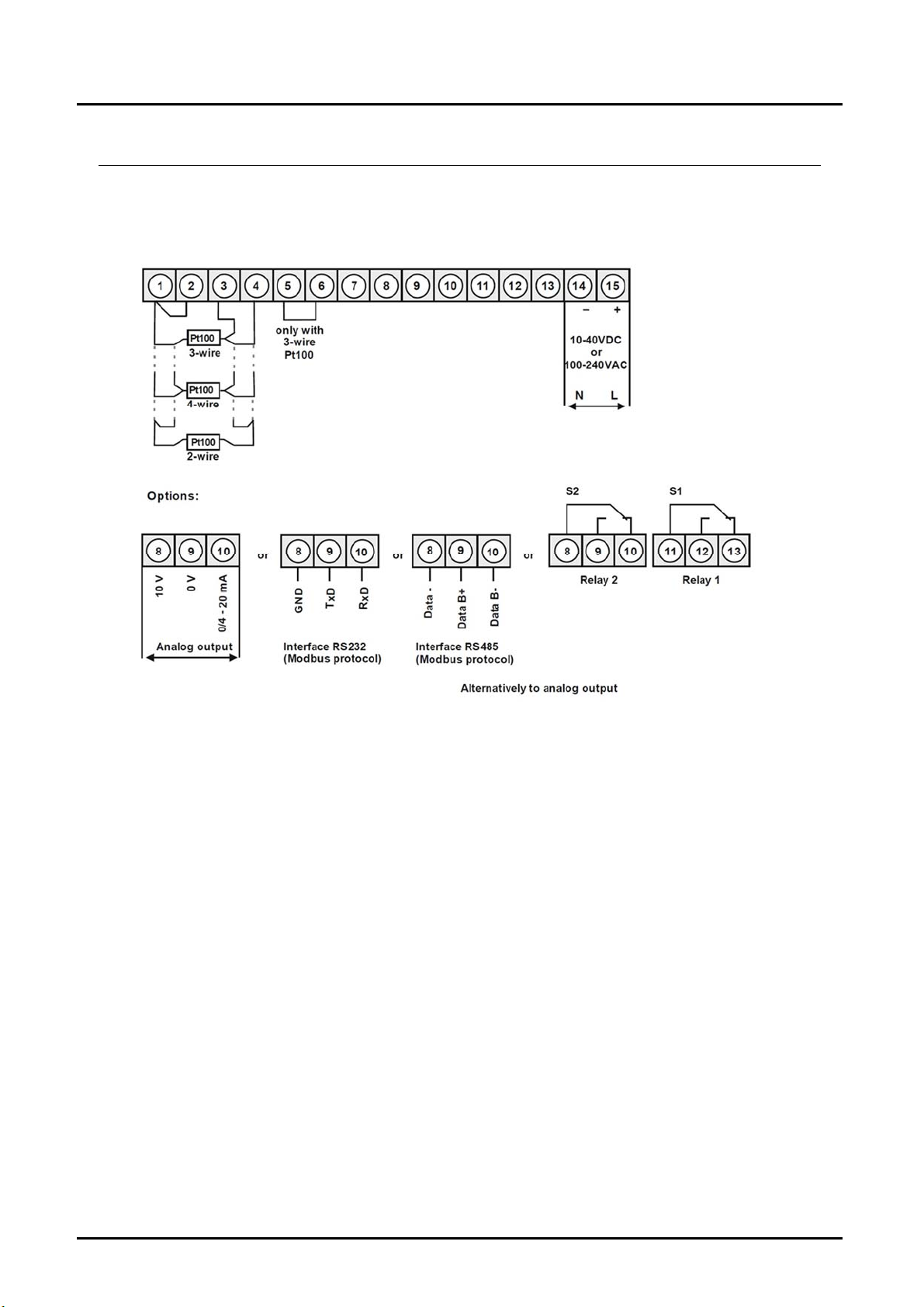
7.Electrical connection ..................................................................................... 7
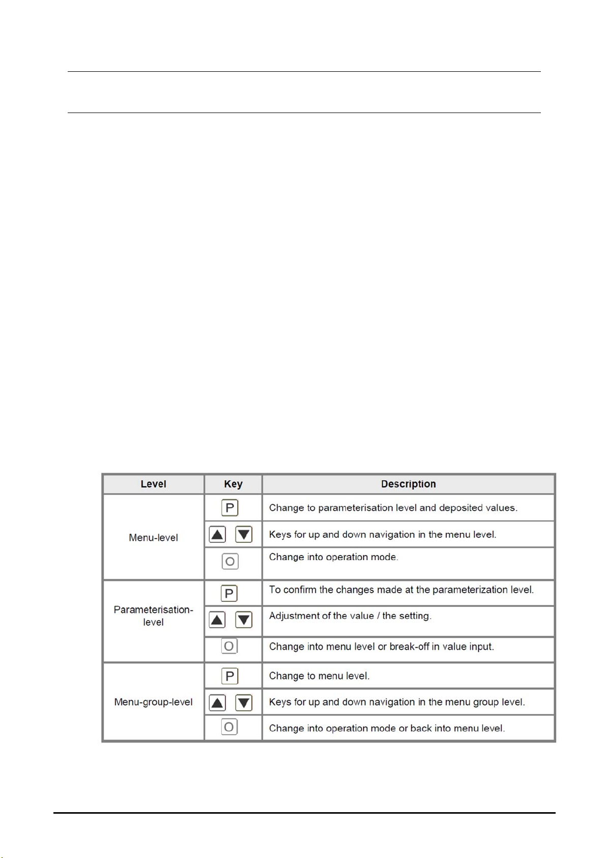
8.Function description and operation ............................................................... 8
9.Setting up the device ................................................................................... 10
9.1Switching on ...................................................................................... 10
9.2Standard parameterization (Flat operation level) ............................... 10
9.3Programming interlock RUN .............................................................. 12
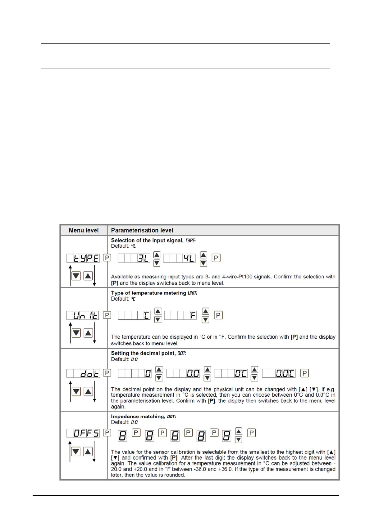
9.4Extended parameterization (Professional operation level) ................. 13
10.Reset to default values ................................................................................ 24
11.Alarms / Relays ........................................................................................... 24
12.Interfaces .................................................................................................... 26
13.Technical Information .................................................................................. 27
14.Order Codes ............................................................................................... 27
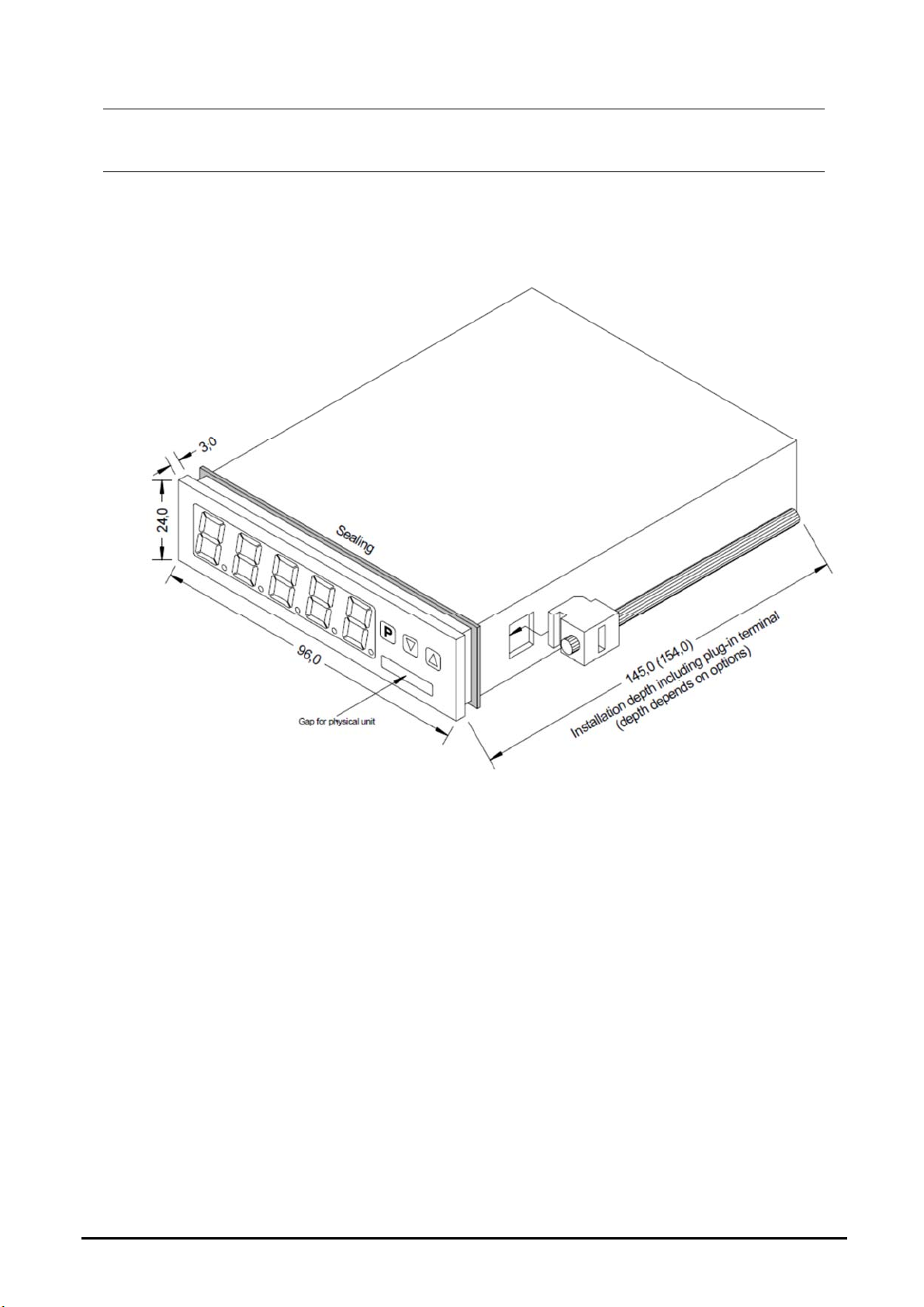
15.Dimensions ................................................................................................. 27
16.Safety advices ............................................................................................. 27
17.Error elimination .......................................................................................... 29
18.Disposal ...................................................................................................... 30
19.EU Declaration of Conformance ................................................................. 31
20.UK Declaration of Conformity ...................................................................... 32
21.Appendix MODBUS Device Interface .......................................................... 33

DAG-M35
DAG-M35 K08/0623 page 3
Manufactured and sold by:
Kobold Messring GmbH
Nordring 22-24
D-65719 Hofheim
Tel.: +49(0)6192-2990
Fax: +49(0)6192-23398
E-Mail: [email protected]
Internet: www.kobold.com

DAG-M35
page 4 DAG-M35 K08/0623
2. Note
Please read these operating instructions before unpacking and putting the unit into
operation. Follow the instructions precisely as described herein.
The instruction manuals on our website www.kobold.com are always for currently
manufactured version of our products. Due to technical changes, the instruction
manuals available online may not always correspond to the product version you
have purchased. If you need an instruction manual that corresponds to the
purchased product version, you can request it from us free of charge by email
([email protected]) in PDF format, specifying the relevant invoice number and
serial number. If you wish, the operating instructions can also be sent to you by
post in paper form against an applicable postage fee.
Operating instructions, data sheet, approvals and further information via the QR
code on the device or via www.kobold.com
The devices are only to be used, maintained and serviced by persons familiar with
these operating instructions and in accordance with local regulations applying to
Health & Safety and prevention of accidents.
When used in machines, the measuring unit should be used only when the
machines fulfil the EC machinery directive.
3. Instrument Inspection
Instruments are inspected before shipping and sent out in perfect condition.
Should damage to a device be visible, we recommend a thorough inspection of the
delivery packaging. In case of damage, please inform your parcel service /
forwarding agent immediately, since they are responsible for damages during
transit.
Scope of delivery:
The standard delivery includes:
Digital indicating unit model: DAG-M35
4. Regulation Use
Any use of the device, which exceeds the manufacturer’s specification, may
invalidate its warranty. Therefore, any resulting damage is not the responsibility of
the manufacturer. The user assumes all risk for such usage.

DAG-M35
DAG-M35 K08/0623 page 5
5. Brief description
The panel meter instrument DAG-M35 is a 5-digit device for Pt100 sensors and a
visual threshold value monitoring via the display. The configuration happens via
four keys at the front. The integrated programming interlock prevents unrequested
changes of parameters and can be unlocked again with an individual code.
Optional available is one analogue output for further evaluation in the unit. With
help of the two galvanic insulated setpoints (optional), free adjustable limit values
can be controlled and reported to a superior master display. The electrical
connection is done via plug-in terminals on the back side. Selectable functions like
e.g. the recall of the min / max. -value, a direct threshold value regulation during
operation mode, complete the modern device concept.

DAG-M35
page 6 DAG-M35 K08/0623
6. Assembly
Please read the Safety advices on page 27 before installation and keep this user
manual for future reference.
1. After removing the fixing elements, insert the device.
2. Check the seal to make sure it fits securely.
3. Click the fixing elements back into place and tighten the clamping screws by
hand. Then use a screwdriver to tighten them another half a turn.
CAUTION! The torque should not exceed 0.1 Nm!
The dimension symbols can be exchanged before installation via a channel
on the side!

DAG-M35
DAG-M35 K08/0623 page 7
7. Electrical connection
Type M358 supply 100-240 VAC 50/60Hz, DC ± 10%
Type M357 supply 10-40 VDC galv. isolated, 18-30 VAC 50/60Hz

DAG-M35
page 8 DAG-M35 K08/0623
8. Function description and operation
Operation
The operation is divided into three different levels.
Menu level (delivery status)
This level is for the standard settings of the device. Only menu items which are
sufficient to set the device into operation are displayed. To get into the professional
level, run through the menu level and parameterize prof under menu item run.
Menu group level (complete function volume)
Suited for complex applications as e.g. linkage of alarms, setpoint treatment,
totalizer function etc. In this level function groups which allow an extended
parameterization of the standard settings are available. To leave the menu group
level, run through this level and parameterize uloc under menu item run.
Parameterization level
Parameter deposited in the menu item can here be parameterized. Functions, that
can be changed or adjusted, are always signalized by a flashing of the display.
Settings that are made in the parameterization level are confirmed with [P] and
thus saved. By pressing the [O] key it leads to a break-off of the value input and to
a change into the menu level. All adjustments are saved automatically by the
device and changes into operating mode, if no further key operation is done within
the next 10 seconds.

DAG-M35
DAG-M35 K08/0623 page 9
Function chart

DAG-M35
page 10 DAG-M35 K08/0623
9. Setting up the device
9.1 Switching on
Once the installation is complete, you can start the device by applying the voltage
supply. Before, check once again that all electrical connections are correct.
Starting sequence
For 1 seconds during the switching-on process, the segment test (8 8 8 8 8) is
displayed followed by an indication of the software type and after that, also for 1
second, the software version. After the starting sequence, the device switches to
operation / display mode.
9.2 Standard parameterization (Flat operation level)
To parameterize the display, press the [P] key in operating mode for 1 second. The
display then changes to the menu level with the first menu item TYPE.

DAG-M35
DAG-M35 K08/0623 page 11

DAG-M35
page 12 DAG-M35 K08/0623
9.3 Programming interlock RUN

DAG-M35
DAG-M35 K08/0623 page 13
9.4 Extended parameterization (Professional operation level)
9.4.1 Signal input parameters

DAG-M35
page 14 DAG-M35 K08/0623
9.4.2 General device parameters

DAG-M35
DAG-M35 K08/0623 page 15

DAG-M35
page 16 DAG-M35 K08/0623

DAG-M35
DAG-M35 K08/0623 page 17
9.4.3 Safety parameters

DAG-M35
page 18 DAG-M35 K08/0623
9.4.4 Serial parameters

DAG-M35
DAG-M35 K08/0623 page 19
9.4.5 Analogue output parameters

DAG-M35
page 20 DAG-M35 K08/0623
Table of contents
Other Kobold Measuring Instrument manuals

Kobold
Kobold NBK-04 User manual

Kobold
Kobold DOG-4 User manual

Kobold
Kobold KAL-K User manual

Kobold
Kobold KSK User manual

Kobold
Kobold ZOE-ZB**FB series User manual

Kobold
Kobold KSM-**001 User manual

Kobold
Kobold DVZ series User manual

Kobold
Kobold OMS User manual

Kobold
Kobold PDC User manual

Kobold
Kobold KSV User manual

Kobold
Kobold KME User manual

Kobold
Kobold DON-05Lx User manual

Kobold
Kobold NUS-4x04 User manual

Kobold
Kobold DAG-M3T User manual

Kobold
Kobold DRS-9180 Series User manual

Kobold
Kobold DRS 0 Series User manual

Kobold
Kobold NMF User manual

Kobold
Kobold DOG Series User manual

Kobold
Kobold DRB Series User manual

Kobold
Kobold SWK User manual