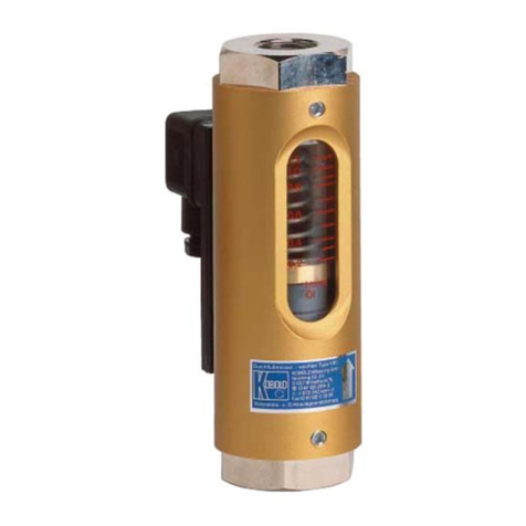
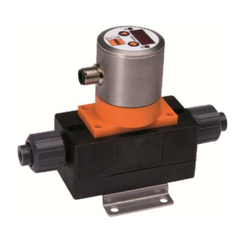
Kobold DFT Series User manual

Operating Instructions
for
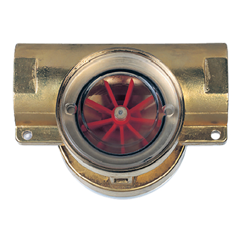
Rotating Vane Flow Meter
Model: DFT

DFT
page 2 DFT K02/0316
1. Contents
1.Contents........................................................................................................2
2.Note ..............................................................................................................3
3.Instrument Inspection....................................................................................3
4.Regulation Use..............................................................................................3
5.Operating Principle........................................................................................4
6.Mechanical Connection.................................................................................4
7.Electrical Connection ....................................................................................5
7.1General ................................................................................................5
7.2Evaluating Electronics (DFT-..0000, ..F400; ..F490, ..L403, ..L443) ....5
7.3Evaluating Electronics DFT-....L442 ....................................................5
7.4MA-Electronics (DFT-...M..) .................................................................6
7.5WM-Electronics (DFT-...W..)................................................................6
7.6DFT-K/E/G (only with cable connection) ..............................................7
8.Operation ......................................................................................................7
8.1MA Electronic (DFT-...M..) ...................................................................7
8.2WM Electronic (DFT-...W..)..................................................................8
8.3K/E/G-Electronic ..................................................................................9
9.Commissioning..............................................................................................9
10.Technical Information..................................................................................10
11.Maintenance ...............................................................................................12
12.Order Codes ...............................................................................................13
13.Dimensions .................................................................................................14
14.EU Declaration of Conformance..................................................................16
Manufactured and sold by:
Kobold Messring GmbH
Nordring 22-24
D-65719 Hofheim
Tel.: +49(0)6192-2990
Fax: +49(0)6192-23398
Internet: www.kobold.com

DFT
DFT K02/0316 page 3
2. Note
Please read these operating instructions before unpacking and putting the unit
into operation. Follow the instructions precisely as described herein.
The devices are only to be used, maintained and serviced by persons familiar
with these operating instructions and in accordance with local regulations
applying to Health & Safety and prevention of accidents.
When used in machines, the measuring unit should be used only when the
machines fulfil the EC-machine guidelines.
as per PED 2014/68/EU
In acc. with Article 4 Paragraph (3), "Sound Engineering Practice", of the
PED 2014/68/EU no CE mark.
Diagram 8, Pipe, Group 1 dangerous fluids
3. Instrument Inspection
Instruments are inspected before shipping and sent out in perfect condition.
Should damage to a device be visible, we recommend a thorough inspection of
the delivery packaging. In case of damage, please inform your parcel service /
forwarding agent immediately, since they are responsible for damages during
transit.
Scope of delivery:
The standard delivery includes:
Rotating Vane Flow Meter model: DFT
Operating Instructions
4. Regulation Use
Any use of the Rotating Vane Flow Meter, model: DFT, which exceeds the
manufacturer’s specifications, may invalidate its warranty. Therefore, any
resulting damage is not the responsibility of the manufacturer. The user assumes
all risk for such usage.

DFT
page 4 DFT K02/0316
5. Operating Principle
The established vane technology has proven itself a million times world wide for
measuring and monitoring the flow of different media through piping. KOBOLD
flow meters/monitors work with this proven principle and offer many benefits.
The heart of the new KOBOLD vane is an embedded ring magnet; it is
hermetically sealed from the flow medium. It transfers, in a non-contacting
manner, the rotary motion of the vane to a Hall sensor attached to the case (in
order to save space). This converts the rotary motion to a frequency signal that is
proportional to the flow rate. The downstream KOBOLD evaluating electronics
can output this signal to a display, convert it to (0(4)-20 mA, 0-10 V) analogue
signal, or count it. It may also be used to switch up to two limit contacts. The
ready and control states of the limit value relay are indicated by LEDs.
The modular design of KOBOLD flow monitors and measuring instruments is a
system that can be universally applied; it is reasonably priced; and requires
minimum space when in service. Very precise measurement results can be
achieved under tough operating conditions with the KOBOLD electronics. The
system is assembled with the electronics and delivered ready for service. The
electronics are adjusted and tuned for use with the sensor. When retrofitted for
other measuring ranges, the system may be readjusted with a similar device at
any time.
6. Mechanical Connection
Before installation
Please ascertain whether the actual flow throughput matches the flow range of
the instrument. The flow range may be obtained from the label.
Warning! If the measuring range is exceeded by more than 20%,
bearing damage may occur.
Remove all packing materials and transport retainers and ensure that no such
materials remain in the device.
Make sure that the maximum operating pressure and temperature of the
device are not exceeded. (see section 10 Technical Information)
Mount the flow indication tension-free into the pipe.
Protect the measuring tube from external damage.
Avoid pressure surges in the measuring tube, such as those arising from fast
start up/shut off of flow or pulsating flow.
The contact-version units may not be installed at a location within an inductive
field.
If possible, it should be checked after mechanical installation, to see if the
connections between union fittings and pipes are properly sealed

DFT
DFT K02/0316 page 5
7. Electrical Connection
7.1 General
Caution! Make sure that the voltage values of your system
correspond with the voltage values of the measuring unit.
Make sure that the supply wires are de-energized.
Connect the power supply and the evaluation oft the output signal to the pins
of the plug described below.
Warning! Incorrect wiring of the connections in the coupling plug
can lead to the electronics being destroyed.
7.2 Evaluating Electronics (DFT-..0000, ..F400; ..F490, ..L403,
..L443)
7.3 Evaluating Electronics DFT-....L442
1
2
3
S+
S-
PE n.c.
1
2
3
PE
+Vs
Signal
Out
GND

DFT
page 6 DFT K02/0316
7.4 MA-Electronics (DFT-...M..)
Cable connection
Wire no. 1 = power supply (-)~
Wire no. 2 = power supply (+)~
Wire no. 3 = anlaogue output (+)
7.5 WM-Electronics (DFT-...W..)
off state or in alarm condition
Cable connection
Wire no: 1= power supply (-)
Wire no. 2= power supply(+)
Wire no. 3
Wire no. 4
Wire no. 5

DFT
DFT K02/0316 page 7
7.6 DFT-K/E/G
(only with cable connection)
Wire
number DFT-K DFT-E DFT-G
1 +24 VDC +24 VDC +24 VDC
2 GND GND GND
3 4-20 mA 4-20 mA 4-20 mA
4 GND GND GND
5 d.c. *) d.c. *) Ctrl 1 *)
6 d.c. *) Reset TM *) Ctrl 2 *)
7 relay S1 N/O relay S1 N/O relay S1 N/O
8 relay S1 COM relay S1 COM relay S1 COM
9 relay S2 N/O relay S2 N/O relay S2 N/O
10 relay S2 COM relay S2 COM relay S2 COM
8. Operation
8.1 MA Electronic (DFT-...M..)
The device is delivered ready for use. The electronics have been calibrated and
fine tuned to the sensor. The calibrating screws (0(4)-20 mA) are behind an
adhesive film and must not be adjusted by the customer. Adjustment by the
customer means that a re-calibration is necessary (and this is chargeable).
Unauthorised opening cancels the guarantee.
As soon as the external power supply to the device is switched on, a green light
emitting diode indicates that it is ready for use.
20 mA
ON
0(4) mA
Remote
Pickup
green LED
(ready for operation)
Do not adjust

DFT
page 8 DFT K02/0316
8.2 WM Electronic (DFT-...W..)
The device is delivered ready for use. The electronics have been calibrated and
fine tuned to the sensor. The calibrating screws ("Zero" and "Range"), next to the
scale button, must not be adjusted by the customer. Adjustment by the customer
means that a re-calibration is necessary (and this is chargeable). Unauthorised
opening cancels the guarantee.
As soon as the external power supply to the device is switched on, a green light
emitting diode indicates that it is ready for use. The red "Alarm" Light emitting
diode flashes.
Attention! When the red light emitting diode is flashing the limit
value relay is in alarm condition (see connection diagram).
The DF-WM has a relay output for monitoring the flow. The condition of the relay
is indicated with a flashing red light emitting diode. The contact is in the form of a
minimum contact, i.e. if the reading drops below the set value the limit value relay
is in alarm condition (flashing red light emitting diode).
Attention! The limit value relay also goes into alarm condition in the
event of a line break or power outage.
Typ:DFT-WM
Green LED
Red LED
Do not adjust
Range
Reference line
Value setter
Key

DFT
DFT K02/0316 page 9
Setting the limit value
Loosen the 4 screws on the transparent electronics cover and remove it.
The limit value is set using the value setter.
Turn the value setter to the desired limit value on the scale to the reference line to
the left of the scale on the font plate.
Calling up the current flow through reading
To measure the actual flow rate it is first necessary to press the red key. This
bypasses the limit value relay and puts it out of action. The flow through can be
determined by simultaneously turning the value setter from the smallest to the
greatest value until the red LED flashes, at which point the flowrate can be read
from the scale on the value setter. After the flow through reading has been read
the value setter is reset to the desired limit value and the button key is released.
Attention! After setting the limit value relay, or calling up the flow
through, screw the transparent cover tightly back onto the
electronics housing. Make sure the flat gasket is sitting correctly.
8.3 K/E/G-Electronic
Detailed information about the functions and operation, refer to the operating
instructions “ZED-K”, “ZED-ZL” and “ZED-ZL”.
9. Commissioning
To avoid pressure surges, the flow medium should be slowly introduced into
the instrument.
Warning! Pressure surges from solenoid valves, ball valves or
similar devices may lead to breakage of the instrument (water
hammer). In the operating condition it must be ensured that the
instrument housing is continuously filled with the flow medium.
Warning! Large air bubbles in the instrument housing can lead to
measuring errors or destruction of the bearings.

DFT
page 10 DFT K02/0316
10.Technical Information
Sensor
Measuring accuracy: 2.5 % f. s.
5 % f. s. (DFT-...0000)
Medium temperature: -20 to +80 °C
Ambient temperature: -20 to +80 °C
Max. operating pressure: 5 bar (PTFE housing)
16 bar (brass housing)
Max. pressure loss: see table
Protection type: IP 65
Materials:
Housing/cover: PTFE or brass
Vane: PTFE
Axle: Ceramics Al2O3 or sapphire
Bearing: PTFE
Gasket: NBR (DFT-11..; DFT-16..)
FEP-O-Seal with silicone
(DFT-13..; DFT-18..)
Front- and back panel: Aluminium, black anodized
( DFT-13..; DFT-18.. only;
not media-contacting)
Screwing: stainless steel
Electronics
Frequency output (OEM)
Power supply: 5-24 VDC
Power input: approx. 5 mA
Signal amplitude high: approx. power supply
Signal amplitude low: = 0.2 V
Output loss: max. 2.5 mW
Electrical connection: connector DIN 43 650
Pulse output: NPN, open collector,
max. 15 mA
Frequency output (option frequency divider)
Power supply: 24 VDC ± 20 %
Power input: 40-50 mA
Signal amplitude high: approx. power supply
Signal amplitude low: = 0.2 V
Output loss: max. 2.5 mW
Electrical connection: connector DIN 43 650
Division factor (option): 0.25...2 factory set
Pulse output: PNP, open collector,
max. 20 mA

DFT
DFT K02/0316 page 11
Analogue output (L electronics)
Power supply: 24 VDC ±20 %
Output: 0-20 mA or 4-20 mA,
3-wire or 2-wire
(2-wire 4-20 mA only)
Max. load: 500 Ohm.
Electrical connection: connector DIN 43 650
Analogue output (MA electronics)
Power supply: 24 VDC +15% / -10 %
24/115/230 VAC ±20 %
Power input: 3.5 W max.
Output: 0(4)-20 mA or 0-10 V
(floating, 24 VDC non-isolated)
Max. load: 500 Ohm.
Electrical connection: 1.5 m cable connection or
connector
Switching output (WM electronics)
Power supply: 24 VDC +15% / -10 %
24/115/230 VAC ±20 %
Power input: 3.5 W max.
Output: changeover contact,
max. 250 V/5 A
Contact resistance: < 100 m.
Electrical connection: 1.5 m cable connection or
connector
“K” electronics with digital display, min/max. contact, analogue output
Display: double-spaced display, illuminated
flow value with selectable units
and bargraph display
Power supply: 24 VDC ±20 %
Current consumption: approx. 100 mA
Electrical connection: 10 wire cable connection
Analogue output: (0)4...20 mA selectable
Load: 0...500 Ω
or 0-10 VDC , Load: >100 kΩ
Switching output: 2 relays, max. 30 V / 2 A
Control elements: via 3 keys
Functions: MIN/MAX memory, flow monitor,
language settings, password protection

DFT
page 12 DFT K02/0316
Counter-Electronics “E”
Display: 2 x 8-digit LCD module, illuminated,
total, part and flow quantity;
units of measurement selectable
Quantity meter: 8-digit
Power supply: 24 VDC ±20 %
Current consumption: approx. 100 mA
Electrical connection: 10-pole cable connection
Analogue output: 0(4)…20 mA selectable
Load: 0…500 Ωor 0-10 VDC, Load: >100 kΩ
Relay outputs: 2 relays,
max. 30 V / 2 A
Control elements: via 4 keys
Functions: Reset, MIN/MAX-memory,
flow monitor, monitoring of
part and total quantities, language
Dosage-Electronics “G”
Display: 2 x 8-digit LCD module, illuminated
dosage, total and flow quantity,
units of measurement are selectable
Quantity meter: 8-digit
Dosage: 5-digit
Power supply: 24 VDC ±20 %
Current consumption: approx. 100 mA
Electrical connection: 10-pole cable connection
Analogue output: 0(4)...20 mA selectable
Load: 0...500 Ωor 0...10 VDC, Load >100 kΩ
Relay outputs: 2 relays,
max. 30 V / 2 A
Control elements: via 4 keys
Function: dosage (relay S2),
start, stop, reset, fine dosage,
correction quantity, flow monitor,
total volume monitoring, language
11.Maintenance
In cases where the flow medium is uncontaminated, the DF-D instrument will
remain maintenance-free. As the rotating vane contains magnets, any ferritic
particles present in the medium can lead to problems. In order to avoid such
problems, we recommend the installation of a magnet filter, eg: magnet filter type
MF-R.
Should cleaning of the instrument become necessary, the housing cover can be
easily removed to provide access to the internals. After cleaning, the instrument
can easily be reassembled. Any work on the electronics may only be undertaken
by the supplier; otherwise the guarantee will become invalid.

DFT
DFT K02/0316 page 13
12.Order Codes
Order Details (Example: DFT-1101 G2 F400)
Measuring range
[L/min] Model Connection
female thread
Brass housing
ceramic axle PTFE housing
ceramic axle Brass housing
sapphire axle PTFE housing
sapphire axle
0.1 - 0.5
0.2 - 2.0
0.5 - 7
1 - 16
DFT-1101..
DFT-1103..
DFT-1107..
DFT-1116..
DFT-1301..
DFT-1303..
DFT-1307..
DFT-1316..
DFT-1601..
DFT-1603..
DFT-1607..
DFT-1616..
DFT-1801..
DFT-1803..
DFT-1807..
DFT-1816..
..G2.. = G 1/4
..G4.. = G 1/2
..N2.. = 1/4 NPT
..N4.. = 1/2 NPT
2-36 DFT-1136.. DFT-1336.. DFT-1636.. DFT-1836..
..G4.. = G 1/2
..G5.. = G 3/4
..N4.. = 1/2 NPT
..N5.. = 3/4 NPT
3-60 DFT-1160.. DFT-1360.. DFT-1660.. DFT-1860.. ..G5.. = G 3/4
..N5.. = 3/4 NPT
Evaluating electronics
OEM frequency output (OEM)
...0000 = NPN, connector DIN 43 650
Frequency output
...F400 = PNP, connector DIN 43 650
...F490 = PNP, connector DIN 43 650, frequency divider 0.25...2
Analogue output
...L403 = connector DIN 43 650, 0 - 20 mA, 3-wire
...L443 = connector DIn 43 650, 4 - 20 mA, 3-wire
..L442 = connector DIN 43 650, 4 - 20 mA, 2-wire
MA electronics with analogue output
Electronic type Auxiliary power Analogue output
..MK.. = 1.5 m cable connection
..MS.. = connector
..MG.. = connector and mating connector
..0.. = 230 VAC
..1.. = 110 VAC
..2.. = 24 VAC
..3.. = 24 VDC
..0 = 0 - 20 mA
..4 = 4 - 20 mA
..1 = 0 - 10 V
MA electronics with analogue output
Electronic type Auxiliary power Analogue output
..WK.. = 1.5 m cable connection
..WS.. = connector
..WG.. = connector and mating connector
..0.. = 230 VAC
..1.. = 110 VAC
..2.. = 24 VAC
..3.. = 24 VDC
..X = without analogue output
K electronics (display, MIN/MAX-contact, analogue output)
Electronic type Auxiliary power Analogue output
..KK.. = 1.5 m cable connection ..3.. = 24 VDC
..0 = 0 - 20 mA
..4 = 4 - 20 mA
..1 = 0 - 10 V
Counter electronics / dosage electronics
Elektronic-type Electrical connection /
power supply Analogue output
E= counter electronics (2 x changer)
G= dosage electronics (2 x changer)
3 = plug 2xM12/24 VDC
1 = 1,5 m cable /24 VDC
9= x m cable /24 VDC
4R = 0(4)-20 mA
1R = 0-10 V

DFT
page 14 DFT K02/0316
13.Dimensions

DFT
DFT K02/0316 page 15
DFT with MA/WM/K electronics (E/G electronics)

DFT
page 16 DFT K02/0316
14.EU Declaration of Conformance
We, KOBOLD Messring GmbH, Hofheim-Ts, Germany, declare under our sole
responsibility that the product:
Rotating Vane Flow Meter Model: DFT
to which this declaration relates is in conformity with the standards noted below:
EN 61000-6-4:2011
Electromagnetic compatibility (EMC) - Part 6-4: Generic standards - Emission
standard for industrial environments
EN 61000-6-2:2006
Electromagnetic compatibility (EMC) - Part 6-2: Generic standards - Immunity for
industrial environments
EN 61010-1:2011
Safety requirements for electrical equipment for measurement, control and
laboratory use - Part 1: General requirements
EN 60529:2014
Degrees of protection provided by enclosures (IP Code)
Also the following EC guidelines are fulfilled:
2014/30/EU EMC Directive
2014/35/EU Low Voltage Directive
2011/65/EU RoHS
2014/68/EU PED
Category II, Table 8, pipe, Group 1 dangerous fluids
Module D, mark CE0098
notified body: Germanischer Lloyd Germany
Hofheim, 07. April 2016
H. Peters M. Wenzel
General Manager Proxy Holder
This manual suits for next models
3
Table of contents
Other Kobold Measuring Instrument manuals
Kobold
Kobold DAG-A14 User manual

Kobold
Kobold HEINRICH DWF-S User manual

Kobold
Kobold DVK-12 User manual

Kobold
Kobold DRB Series User manual

Kobold
Kobold KDF-9 User manual

Kobold
Kobold HND-P105 User manual

Kobold
Kobold KAL User manual

Kobold
Kobold DRS 0 Series User manual

Kobold
Kobold SMN-1150 H Series User manual

Kobold
Kobold DRS-9180 Series User manual

Kobold
Kobold REG User manual

Kobold
Kobold URB User manual

Kobold
Kobold VKG User manual

Kobold
Kobold KEC-2 User manual

Kobold
Kobold MIS User manual

Kobold
Kobold NBK-ATEX Series User manual

Kobold
Kobold KDF-2 Series User manual

Kobold
Kobold OME User manual

Kobold
Kobold HND-F205 User manual
Kobold
Kobold MIM User manual