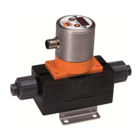
Kobold MIS User manual

Operating Instructions
for
Electromagnetic Flowmeter
Model: MIS

MIS
page 2 MIS K01/0719
We don’t accept warranty and liability claims neither upon this publication nor in
case of improper treatment of the described products.
The document may contain technical inaccuracies and typographical errors. The
content will be revised on a regular basis. These changes will be implemented in
later versions. The described products can be improved and changed at any time
without prior notice.
© Copyright
All rights reserved.

MIS
MIS K01/0719 page 3
1. Contents
1.Contents ....................................................................................................... 3
2.Note .............................................................................................................. 5
2.1Overview of the device functionality .................................................... 5
3.Instrument Inspection.................................................................................... 6
4.Regulation Use ............................................................................................. 6
5.Environment.................................................................................................. 6
6.Operating principle........................................................................................ 7
6.1General................................................................................................ 7
6.2Minimum electrical conductivity / Gas bubbles .................................... 7
6.3Deposits............................................................................................... 7
6.4Measuring electrodes .......................................................................... 7
7.Mechanical connection ................................................................................. 8
7.1Receipt of goods and transport ............................................................ 8
7.2Installation requirements...................................................................... 9
7.3Installation ......................................................................................... 10
8.Electrical Connection .................................................................................. 18
8.1General.............................................................................................. 18
8.2Pin assignment .................................................................................. 18
8.3Connection example outputs: ............................................................ 19
9.Operation and menu structure .................................................................... 20
9.1General.............................................................................................. 20
9.2Measuring mode................................................................................ 21
9.3Menu Mode........................................................................................ 24
10.Device configuration ................................................................................... 26
10.1Sequence of device parameterization................................................ 26
10.2Language........................................................................................... 26
10.3Display............................................................................................... 27
10.4Measurement..................................................................................... 29
10.5Dosing function.................................................................................. 33
10.6Outputs .............................................................................................. 33
10.7User service....................................................................................... 44
10.8Service / Factory service ................................................................... 45
10.9Info..................................................................................................... 45
10.10Device default settings....................................................................... 46
11.Status.......................................................................................................... 47
12.Dosing function ........................................................................................... 48
13.IO-Link function........................................................................................... 52
13.1Specification ...................................................................................... 52
14.Technical Information.................................................................................. 53
15.Order Codes ............................................................................................... 55
16.Dimensions ................................................................................................. 56
17.Annex.......................................................................................................... 57
17.1IO-Link process data structure........................................................... 57
17.2IO-Link diagnostic information ........................................................... 58
17.3IO-Link device-specific system commands........................................ 59

MIS
page 4 MIS K01/0719
17.4IO-Link ISDU Parameter table ...........................................................60
18.Manufacturer’s Declaration .........................................................................71
19.EU Declaration of Conformance .................................................................72
Manufactured and sold by:
Kobold Messring GmbH
Nordring 22-24
D-65719 Hofheim
Tel.: +49(0)6192-2990
Fax: +49(0)6192-23398
Internet: www.kobold.com

MIS
MIS K01/0719 page 5
2. Note
Please read these operating instructions before unpacking and putting the unit
into operation. Follow the instructions precisely as described herein.
The devices are only to be used, maintained and serviced by persons familiar
with these operating instructions and in accordance with local regulations
applying to Health & Safety and prevention of accidents.
When used in machines, the measuring unit should be used only when the
machines fulfil the EC-machine guidelines.
as per PED 2014/68/EU
In acc. with Article 4 Paragraph (3), "Sound Engineering Practice", of the PED
2014/68/EU no CE mark.
2.1 Overview of the device functionality
Depending on the installed device firmware, the MIS device may have
different functionalities. The functional extensions are shown in the
following table.
Function extension Available from firmware version
Dosing function REV180118
Menu languages
Simulation function
User function keys
Analogue output 2-10 VDC
Analogue output behavior acc. to NAMUR NE43
REV180514
IO-Link
Control input REV190320
The installed software version is displayed after starting the device below the
manufacturer logo in the form REVxxxxxx for approx. 2 sec.

MIS
page 6 MIS K01/0719
3. Instrument Inspection
Instruments are inspected before shipping and sent out in perfect condition.
Should damage to a device be visible, we recommend a thorough inspection of
the delivery packaging. In case of damage, please inform your parcel service /
forwarding agent immediately, since they are responsible for damages during
transit.
Scope of delivery:
The standard delivery includes:
Electromagnetic Flowmeter model: MIS
Operating Instructions
4. Regulation Use
The MIS flowmeter has been specially developed for the measurement, display
and transmission of both, flow rates and temperature of conductive liquids. The
instrument has a graphic TFT display, rotatable in 90 ° steps and can display flow
rate, temperature, daily volume counter (resettable) and total volume counter in
the units of measurement selected by the operator. A clear menu guides the user
through the parameterization of the device, which largely eliminates the need to
look into the operating instructions.
Any use of the magnetic flowmeter, model: MIS, which exceeds the
manufacturer’s specification, may invalidate its warranty. Therefore, any resulting
damage is not the responsibility of the manufacturer. The user assumes all risk
for such usage.
5. Environment
The MIS device with stainless steel housing and stainless steel electrodes is
weatherproof and conforms to protection class IP67. The meter is designed for
harsh indoor or outdoor environments and complies with Directive 2014/30/EU
(Electromagnetic Compatibility).

MIS
MIS K01/0719 page 7
6. Operating principle
6.1 General
The new KOBOLD MIS Flowmeter is designed to measure and monitor small and
medium flows of conductive fluids in piping.
The device works on the magnetic-inductive measuring principle. According to
Faraday's law of induction, a voltage is induced in a conductor moving in a
magnetic field. The electrically conductive measuring medium corresponds to the
moving conductor in the process. The voltage induced by the measuring medium
is proportional to the flow rate and thus a measure of the volume throughput.
Prerequisite is a minimum electrical conductivity of the flowing medium. The
induced voltage is fed to a measuring amplifier via two electrodes, which are in
conductive contact with the medium. The volume flow is calculated via the
defined pipe diameter.
The measurement is independent of the medium and its physical properties such
as density, viscosity and temperature. The device can be configured via the
display. There are two outputs available, which can each be configured as alarm,
frequency, pulse, voltage, and current outputs.
The device also provides a dosing function. The dosing function can be activated
in measuring mode via the four buttons. The dosing function controls simple filling
tasks and also measures flow rate and partial amount.
6.2 Minimum electrical conductivity / Gas bubbles
For the correct function of the instrument, it is necessary that the flow channel is
always completely filled with medium. From a minimum electrical conductivity of
20 S / cm, the MIS operates within the specified error limits. The conductivity of
the medium is constantly monitored by the device electronics. If the electronics
detects that the minimum conductivity has fallen below min. value, this is signaled
by displaying the error message 'Empty pipe' and the flow rate reading is set to
'0'. Air bubbles in the flowing medium or media with varying conductivity in the
range of the minimum conductivity can disturb the measuring function and reduce
the measuring accuracy of the MIS. Gases contained in the liquid are also
measured as a flow volume and lead to measurement errors. If necessary, install
appropriate vents in the flow of the unit.
6.3 Deposits
Minor deposits on the measuring tube generally do not affect the measuring
accuracy unless their conductivity deviates significantly from the liquid. For liquids
that have a tendency to deposit, periodically inspect the meter tube and, if
necessary, clean it.
6.4 Measuring electrodes
The MIS uses electrodes with galvanic tapping. They are in direct contact with the
medium. The standard electrodes are made of Hastelloy.

MIS
page 8 MIS K01/0719
7. Mechanical connection
7.1 Receipt of goods and transport
7.1.1 Receipt of goods
Check the packaging and contents for damage.
Inspect the supplied goods to ensure complete delivery and compare the
consignment with your order
specifications.
7.1.2 Transport
Please observe the following tips when unpacking your device, or transporting it to
its measuring point:
If possible the devices should be forwarded in the packaging in which they
were delivered.
Do not remove any protection disks or caps from the process connections.
This is particularly important in the case of sensors with a PTFE flow tube
lining. The protection caps should only be removed immediately before
installation of the device in the pipe.
Never lift the devices by the mounted transmitter housing or terminal box
for transport. When transporting heavy devices, use slings. Place these
around both process connections. Do not use chains as these can damage
the surface coating and the housing.
When transporting devices without lugs, and when looping the slings
around the flow tube, the center of gravity of the entire device can be higher
than both attachment points of the slings. When transporting the device
ensure that it does not rotate or slip accidentally. This could cause injury.
Sensors with a nominal size of more than DN 150 should not be lifted by
the sheet metal of the shell with a forklift truck. This could dent the sheet
metal of the shell and damage the internal solenoid coils. There is also the
risk that the device could roll off the forks.
If the sensor is provided with PTFE (Teflon) lining, then, upon delivery, the
sensor is mounted with two wooden discs, to hold the lining in position
during transport and storage. These wooden discs should remain on the
sensor until installed. Without the discs, the liner creeps back to its original
shape and installation is more difficult to do. The sensor should be left for at
most a few hours without the discs. Remove the discs immediately before
installation.

MIS
MIS K01/0719 page 9
7.2 Installation requirements
The installation location in the pipe must be selected so that the sensor is always
fully filled with the fluid
and cannot run empty. This can best be guaranteed if it is
installed in an ascending pipe or drain.
The measuring principle is generally independent of the flow profile of the fluid
provided no standing
vortices reach into the area of measurement, such as from
elbows or half-open sliding valves upstream
from the sensor. In these cases
measures must be taken to normalize the flow profile. Practical
experience has
shown that in most cases a straight inlet section of ≥5 x DN and an outlet
section of ≥
2 x DN of the nominal sizes of the sensor is sufficient. The
occurrence of strong electromagnetic fields in
the vicinity of the installed sensor
must be avoided.
For the Implementation of forward and backward flow measurements, both sides
of the sensor must be
provided with a straight pipe section with the nominal sizes
of the sensor and a length of 5 DN of the
nominal sizes of the sensor. It is
advisable to install actuators, such as regulating or shut-off devices,
downstream
from the sensor. The forward flow direction is marked on the sensor with an arrow.
When
mounting sensors, always observe the specified screw torques.
After the installation of the sensor and the electrical connections between the
sensor and the transmitter
has been made, the system can be taken into
operation. To prevent measuring errors caused by gas
pockets in the fluid and
damage to the lining of the sensor caused by negative pressure, the following
points
must be observed:
7.2.1 Bypass pipes
To allow for a problem-free dismount, emptying and cleaning of the sensor, a
bypass pipe may be installed.
The bypass with a blind flange permits the fluid pipe
to be cleaned without having to dismount the flowmeter.
This is recommended for
highly soiled fluids.
7.2.2 Sensor tube lining
If the flow tube is lined with PTFE, the flowmeter must be installed with special
care. The tube lining is
bordered at the flanges (seal). This must not be damaged
or removed as it prevents the fluid from
penetrating between the flange and flow
tube destroying the electrode insulation.

MIS
page 10 MIS K01/0719
7.3 Installation
Screws, bolts, nuts and seals are not in the scope of delivery and must therefore
be
provided by the operator. The sensor is to be installed between the pipes.
Please observe the required
torques stated Section “Torques for screws and
bolts”. The installation of additional grounding rings is
described in Section
“Earthing – potential equalisation”. Use for the flanges only gaskets in accordance
with DIN EN 1514-1. Mounted gaskets must not reach into the pipe cross-section.
Caution!
Do not use conductive sealing compounds such as graphite. This could result in a
conductive
layer building up on the inside of the flow tube, short-circuiting the
measuring signal.

MIS
MIS K01/0719 page 11
7.3.1 Installation in pipelines with larger nominal sizes
The flowmeter can also be installed in pipes with larger nominal sizes by using
pipe tapers (e.g. flange
transition pieces in accordance with DIN EN 545).
However, the resulting pressure loss must be taken
into consideration. To avoid
flow interruptions in the flow tube, a reducing angle of 8° for the tapers
should
be exceeded.
7.3.2 Horizontal or vertical Installation
The installed position of the flowmeter is arbitrary, however the intended x-y
electrode axis should run
approximately horizontal. A vertical Electrode axis
should be avoided, since gas pockets or solid particles
carried along in the fluid
could affect the accuracy of the device.
x
y x
y

MIS
page 12 MIS K01/0719
7.3.3 Installation examples
To avoid measuring errors evoked by gas pockets or lining damage caused by
negative pressure, the
following points must be observed:
Vibrations
To eliminate the effects of vibrations and prevent premature damage to the
transmitter, the sensor shall be
supported in the near vicinity of the flanges.
Horizontal pipeline routing
Install preferably in slightly ascending pipes.
Open inlet or outlet
Where possible, the device should be installed in a syphon. The empty pipe
detection circuit of the
transmitter is an additional safety feature for recognizing
empty or partially filled pipes.
Caution! There is the danger of accumulation of solids in the siphon. The
installation of a cleaning aperture
in the pipe is therefore advisable.

MIS
MIS K01/0719 page 13
Down pipes
Where down pipes are to be found in the pipe system, a syphon or a ventilation
valve should be placed
after the sensor. By these means, negative pressure can
be avoided in the pipeline, which may otherwise
damage the sensor lining. This
measure will also prevent a breakdown of the flow reducing the risk of air
inclusions in the measurement medium.
Long pipelines
In long pipelines there is always a danger of pressure surges. Therefore
regulating and shut-off devices
should be placed behind the sensor. However,
when installed in vertical piping, especially when using
sensors with PTFE-lining
and high operating temperatures, the regulating and shut-off devices should be
placed in front of the sensor (danger of vacuum).
5 m

MIS
page 14 MIS K01/0719
Installation of pumps
To avoid negative pressure and eventual damage to the tube lining, never install
flowmeters on the
suction side of pumps.
If necessary, arrange for pulsation dampeners when using piston, diaphragm or
hose
pumps.
Consider the space requirements beforehand with respect to a potential
deinstallation
of the device.
7.3.4 Earthing – potential equalisation
The sound grounding concept of the flowmeter is a necessity for both safety
reasons as well as to ensure
a faultless operation. In accordance with VDE
0100 Part 410 and VDE 0100 Part 540 the grounding
connections must be at
protective conductor potential. For metrological reasons, this potential must be
identical to the potential of the fluid. The grounding cable should not transmit
any interference voltage.
For this reason do not simultaneously ground other
electrical devices with this cable.
The measuring signal tapped at the electrodes amounts to only a few millivolts.
Correct grounding of the
electromagnetic flowmeter is therefore an important
prerequisite for exact measurement. The transmitter
requires a reference
potential to evaluate the measured voltage on the electrodes. In the simplest case
the
non-insulated metal pipe and/or the connecting flange may be used as a
reference potential.
Where pipes are lined with electrically insulating materials or pipes are made of
plastic, the reference
potential can be obtained from a grounding ring or
grounding electrode. These establish the necessary
conductive connection to the
fluid and are made of a chemical-resistant material. The material used should
be
identical to that of the measuring electrodes

MIS
MIS K01/0719 page 15
7.3.5 Earthing with earthing electrodes
The device can be optionally equipped with grounding electrodes. With plastic
pipes this version is the
easiest grounding method. As the surface of the
grounding electrode is relatively small, the use of
grounding rings on both sides
of the sensor is preferable in systems in which high equalizing currents along
the
pipeline can be expected to occur.
7.3.6 Earthing with earthing rings
The outside diameter of the grounding ring should be at least equal to the
diameter of the flange or be
dimensioned in such a way that the grounding ring
is positioned inside the flange bolts and is centered by
these. The terminal lugs
routed to the outside must be connected to the FE terminal in the junction box of
the sensor. During installation ensure that the inner diameter of the seals do
not protrude over the
grounding disk!
The grounding cables are not included in the scope of your delivery and
must be provided by the
plant operator.
The grounding rings can be ordered as accessories.
7.3.6.1 Examples of earthing the MIS
7.3.6.1.1 Metal piping electrically conductive
FE/PE
Pipe
Pipe
Ground wire min. 4 mm
2
Cu

MIS
page 16 MIS K01/0719
7.3.6.1.2 Plastic piping, or internally coated metal piping
7.3.6.1.3 Cathodic piping protection
Special care must be taken with cathodic protection pipelines.
For compact installation:
The transmitter must be powered by an isolation transformer.
The connection
"PE" must never be connected.
With separate installation:
The shield must be connected to the sensor end via a 1.5 F capacitor.
The
shield must never be connected to both ends.
For isolated installation:
If the above connections are unacceptable, isolate the sensor from the piping.
Pipe
Pipe
Gasket
Gasket
Ground wire min. 4 mm
2
Cu
Grounding ring
Grounding ring
FE/PE

MIS
MIS K01/0719 page 17
7.3.7 Torques for screws and bolts
Due to the fact that the flow pipe lining is made of plastic or vulcanized materials
such as hard rubber. Or
PTFE, electromagnetic flowmeters must be installed in
pipe system with special care since these materials
are malleable under pressure.
If the flange screws are overtightened, the sealing surface will deform. If the
seals
are to function properly, the correct torque is highly important.
Tighten the screws crosswise so that the process connections are tight. When
tightening the screws for
the first time approx. 50 percent of the required torque
should be reached, for the second time the torque
should be 80 percent. The
required torque should reach 100 percent when the screws are tightened for the
third time. For higher torques it is advisable to use protectors.
The maximum permissible torques can be obtained from the following table
mm
inch
NBR Ebonite / soft rubber PTFE DN2 + DN3 zirconium;
DN6
PN10 PN16 PN40
DN2
AWWA PN10 PN16 PN40 PN6 PN10 PN16 PN25 PN40
Nm f/lbs Nm f/lbs Nm f/lbs Nm f/lbs Nm f/lbs Nm f/lbs Nm f/lbs Nm f/lbs Nm f/lbs Nm f/lbs Nm f/lbs Nm f/lbs Nm f/lbs Nm f/lbs
2 - - - - - - - - - - - - - - - - - - - - - - - - - - - 13 10
3 - - - - - - - - - - - - - - - - - - - - - - - - - - - 13 10
6 - - - - - - - - - - - - - - - - - - - - - - - - - - - 13 10
10 - - - - - - - - - - - - - - - - - - - - - - - - - - - 13 10
15 ½" - - - - - - - - - - - - - - - - - - - - - - - - 10 7 16 12
25 1" - - - - 10 7 7 5 - - - - - - 16 12 - - - - - - - - 16 12 30 22
40 1½" - - - - 16 12 9 7 - - - - - - 34 25 - - - - - - - - 34 25 54 40
50 2" - - 25 18 - - 25 18 - - - - - - 46 34 - - - - - - - - 46 34 90 66
65 2½" - - 25 18 - - 25 18 - - - - 25 18 - - 10 7 - - 25 18 - - 34 25 90 66
80 3" - - 25 18 - - 34 25 - - - - 25 18 - - 25 18 - - 25 18 - - 42 31 90 66
100 4" - - 25 18 - - 26 19 - - - - 25 18 - - 25 18 - - 25 18 - - 72 53 115 84
125 5" - - 29 21 - - 42 31 - - - - 32 24 - - 25 18 - - 32 24 - - 114 84 - -
150 6" - - 50 37 - - 57 42 - - - - 50 37 - - 25 18 - - 50 37 - - 144 106 - -
200 8" 50 37 50 37 - - 88 65 - - 50 37 52 38 - - 25 18 50 37 52 38 105 77 185 137 - -
250 10" 50 37 82 61 - - 99 73 - - 50 37 88 65 - - 25 18 50 37 88 65 160 118 300 221 - -
300 12" 57 42 111 82 - - 132 97 - - 62 46 117 86 - - 50 37 62 46 117 86 170 125 320 236 - -
350 14" 60 44 120 89 - - 225 166 - - 60 44 120 89 - - 50 37 60 44 120 89 240 177 450 332 - -
400 16" 88 65 170 125 - - 210 155 - - 88 65 170 125 - - 50 37 88 65 170 125 330 244 650 480 - -
450 18" 92 68 170 125 - - 220 162 - - 92 68 170 125 - - 56 41 92 68 170 125 320 236 570 421 - -
500 20" 103 76 230 170 - - 200 148 - - 103 76 230 170 - - 53 39 103 76 230 170 390 288 740 546 - -
600 24" 161 119 350 258 - - 280 207 - - 161 119 350 258 - - 81 60 161 119 350 258 560 413 122 900 - -
700 28" 200 148 304 224 - - - - 200 148 200 148 304 224 - - - - - - - - - - - - - -
750 30" - - - - - - - - 240 177 - - - - - - - - - - - - - - - - - -
800 32" 274 202 386 285 - - - - 260 192 274 202 386 285 - - - - - - - - - - - - - -
900 36" 288 213 408 301 - - - - 240 177 288 213 408 301 - - - - - - - - - - - - - -
1000 40" 382 282 546 403 - - - - 280 207 382 282 546 403 - - - - - - - - - - - - - -
42" - - - - - - - - 280 207 - - - - - - - - - - - - - - - - - -
1100 44" - - - - - - - - 290 214 - - - - - - - - - - - - - - - - - -
1200 48" 395 292 731 539 - - - - 310 229 395 292 731 539 - - - - - - - - - - - - - -
Torque - calculation:
1)
All bolts are new and the material selection complies with EN 1515-1 Table 2
2)
Sealing material of maximum 75 Shore A hardness will be used between the flow meter
and the
associated flanges
3)
All bolts are galvanized and greased accordingly
4)
The values are calculated for use with carbon steel flanges
Flow meter and associated flanges are properly aligned

MIS
page 18 MIS K01/0719
8. Electrical Connection
8.1 General
Attention! Make sure that the voltage values of your system
correspond with the voltage values of the measuring unit.
Make sure that the supply wires are de-energised.
Connect the supply voltage and the output signal to the plug PIN’s as stated
below.
We recommend the use of wires with cross sectional area of min. 0.25 mm².
Attention! The measuring electrodes are galvanically connected
with the reference potential of the supply voltage and the signal
output.
8.2 Pin assignment

MIS
MIS K01/0719 page 19
8.3 Connection example outputs:
OUT2: analogue output 4-20 mA
OUT1: analogue output 0-10 V
Configurable output functions:
Out 1 Out 2
analogue output 4-20 mA analogue output 4-20 mA
analogue output 0-20 mA analogue output 0-20 mA
analogue output 2-10 V analogue output 2-10 V
analogue output 0-10 V analogue output 0-10 V
alarm output alarm output
pulse output pulse output
frequency output frequency output
communication mode
KofiCom
communication mode IO Link
control input
control input dosing function dosing output

MIS
page 20 MIS K01/0719
9. Operation and menu structure
9.1 General
9.1.1 Operation of the optical buttons
An optical button is located at each corner of the TFT display. The operability of
the respective buttons is signaled by blue backlighting; therefore non-backlit
buttons are disabled and cannot be operated. To operate the keys, the finger
must be placed on the key-dome and raised again. The orange background of the
button symbols is briefly displayed in blue as visual feedback for a detected key
press.
To avoid accidental operation in measuring mode, the operator must hold down
the menu button for 3-5 seconds to activate the function. If the menu button is
held down for more than 3 seconds, the blue backlighting will begin to flash to
alert the user to release the button.
The operation of the optical buttons can also be done with gloves or other
optically reflective objects, light dirt on the surface usually does not interfere with
the key function.
9.1.2 Function of the control buttons
The function of each control key can be recognized by the respective symbol
displayed in the corners of the TFT display.
key symbol designation function
Measuring mode menu mode
menu mode
Activate menu
mode
hold 3-5 sec.
-
info display opens the info
menu -
down -
Scroll down menu /
decrease numeric
value when entering
numeric value
Deactive optical button
Optical button active
Table of contents
Other Kobold Measuring Instrument manuals

Kobold
Kobold DAG-M45 Series User manual

Kobold
Kobold NBK-01 User manual

Kobold
Kobold BVO Series User manual

Kobold
Kobold KAL User manual

Kobold
Kobold DRS-9180 Series User manual

Kobold
Kobold OME Series User manual

Kobold
Kobold DAG-M3F User manual

Kobold
Kobold URM User manual

Kobold
Kobold Heinrichs K09 User manual

Kobold
Kobold HND-P215 User manual

Kobold
Kobold PDC User manual

Kobold
Kobold OPT-Y24896/0001 User manual

Kobold
Kobold ZOE-ZB**FB series User manual

Kobold
Kobold DRG User manual

Kobold
Kobold DAG-M35 Series User manual

Kobold
Kobold MAS User manual

Kobold
Kobold AFS-G1 User manual

Kobold
Kobold Heinrichs K12 User manual

Kobold
Kobold ZUB-MANS-KON1/2 User manual

Kobold
Kobold DPT Series User manual