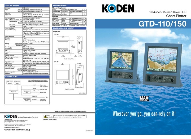
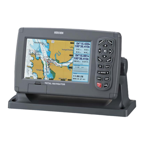
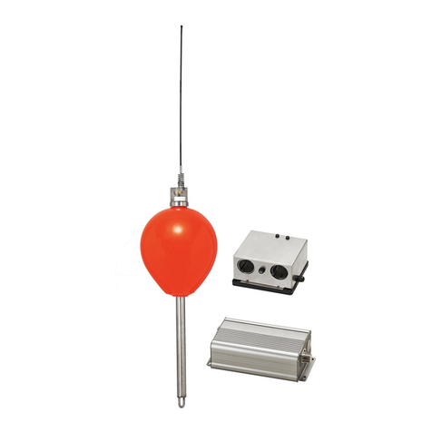
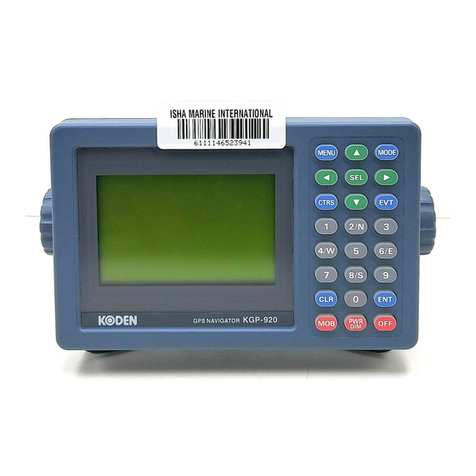
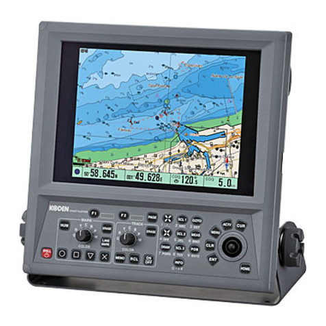
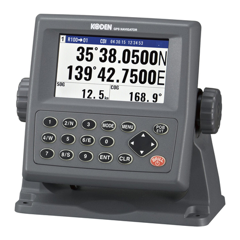
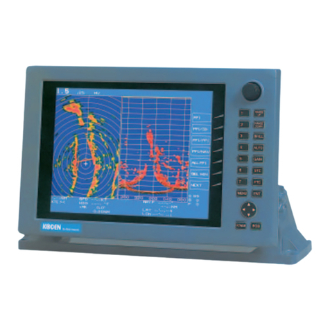
Koden GTD-110 User manual


Amendment History
GTD-110/150 Operation Manual
Doc No: 0093151542
No. Document No &
Rev No. Date Amendments
0 93151542-00 03/01/09 First issue
1 93151542-01 03/07/14
Amended cable type names shown in Figure 1.1 (Page 1-3),
Para 2.1 and 2.2 (Page 2-1.
2 93151542-02 04/06/02 KODEN:Address
3 93151542-03 05/06/07 Preface;Chapter_6 6.6.11
4 0093151542-04 06/01/27 Cover
5 0093151542-05 06/07/03 Cover
6 0093151542-06 06/07/26 Chapter_5, Chapter_6
7
8
9
10
11
12
13
14
15
16
17
18
19
20
Amendment policy
When any change is applied in the document, only the document number of the relevant sheet(s) and
cover sheet are modified and the rest of the sheets are not changed. The document number is shown in
the footer area, right or left bottom of each sheet.
○
c2002 2003 2004 2005 2006 Koden Electronics Co.,Ltd. All rights reserved.
No part of this publication may be reproduced, transmitted, translated in any form by any means without
the written permission of Koden Electronics Co., Ltd. The technical descriptions contained in this
publication are subject to change without notice. Koden assumes no responsibility for any errors,
incidentals or consequential damages caused by misinterpretation of the descriptions contained in this
publication.

GTD-110/150 Preface
93151542-03 (1)
Safety Precautions
zDisconnect Main Power
It is still possible to receive an electric shock caused by unintentionally switching on the power during
repair work. To prevent this from happening, make sure to completely disconnect the unit from the
ship’s main supply before attempting any inspection and repair.
zDust
Dust can accumulate inside the unit after long periods of use. Allergies can result from the inhalation of
this dust, therefore during inspection and cleaning it is advisable to use a mask.
zStatic Electricity
Static sensitive semiconductor devices are used in this unit. Before changing the printed boards be
careful not to damage any of these devices due to electrostatic build up from carpet, clothes, seats, etc
zDisplay Front Plate
A glass plate is used in front of the Liquid Crystal Display in the GTD-110 display unit. The glass is
vulnerable against mechanical impact. Use the utmost care when handling this unit, not to apply
mechanical shock to this part. In the GTD-150 unit, a plastic plate is used for the same purpose, which
is stronger than the glass, however, the same caution should be taken.
zLiquid Crystal Display
A Liquid Crystal Display contains mercury, which is harmful to the human body when touched. When
you attempt to discard this device, follow the proper disposal procedures.
Operational Precautions
Navigational information shown on the GTD-110/150 series Track Display should be used as reference
only. KODEN would not assume any responsibility for trouble encountered on board the ship caused by
operational failure nor misinterpretation of the chart used.

Preface GTD-110/150
(2) 93151542-03
Symbols used in this manual
The following symbols are used in this manual. You are requested to be fully aware of the meaning of
each symbol before carrying out inspection and maintenance of this equipment.
Alarm mark
Caution mark
Warning High Voltage mark
Prohibition mark
To handle the equipment ignoring this sign may lead to injury to the
human body or damage to the equipment.
Alarm
To handle the equipment ignoring this sign may lead to an electrical
shock to the human body.
This sign indicates that a specified action is prohibited. The
prohibited action will be shown in the vicinity of the mark.
To handle the equipment ignoring this sign may lead to a
malfunction in the equipment.
Caution

GTD-110/150 Preface
93151542-03 (3)
How to use this manual
Scope of this manual
This manual contains information about installation, operation and maintenance of the GTD-110/150
series Track Display.
Structure of this manual
This manual is divided into sections according to the contents as described below. This arrangement
will help you overview the whole contents as well as refer to detailed information for your specific
requirement.
Chapter 1: General Information
-About GPS
-Outline of the equipment
-Applicable standards
-Equipment composition
-Software type name
Chapter 2: Equipment Composition
-Standard Equipment list
-Optional items list
Chapter 3: Specification
-Specification
-Serial data
-Power requirements
-Environmental conditions
-External dimensions and weight
Chapter 4: Installation
-Installation consideration
-Unpacking of the goods
-Inspection of the goods
-Siting the units
-Cable routing and connections

Preface GTD-110/150
(4) 93151542-03
-Display Installation
-Cable connections
-Inspections after installation
Chapter 5 : Basic Operations
-Operating controls and functions
-Getting started
-Displaying the current position
-Operation on the map display
-Mark registration
-Setting up for Waypoint Navigation
-Marking the POB (Person Over Board) location
-Changing the screen top direction
-Object information
Chapter 6: Using the Menu
-Menu functions
-Mark block number
-Setting the alarm
-Display settings
-Setting the KODEN GPS/DGPS sensor
-System settings
-Mark edit
-Operation of blocks
-GPS Monitor
-Maintenance
-Drawing
Chapter 7: Route navigation
- Routes
-Texts for marks
-
Chapter 8: Trouble Shooting
-Information required for service
-First line fault location

GTD-110/150 Preface
93151542-03 (5)
Chapter 9: Maintenance
-Periodic inspection and cleaning
Chapter 10: Technical References
-Details of input serial data
-Details of output serial data
-Data input/output serial line
-Connector pinouts
Annex:
-Menu tree
-Color palette list

GTD-110/150 Chapter 1
General Information
93151542-00 Contents
Chapter 1
General Information
Contents
Page No.
1.1 About GPS ……………………………………….…....…1-1
1.1.1 General……………………..……….………………….…1-1
1.1.2 Positioning by GPS …………………..………………….1-1
1.1.3 Time required for position fix….………………...………1-1
1.2 Outline of the equipment………………………….…..…1-2
1.3 Applicable standards ……………………………….……1-2
1.4 Equipment composition …………………………………1-2
1.5 Software type name …………………..……..…………. 1-2

GTD-110/150 Chapter 1
General Information
93151542-00 1-1
Chapter 1 General Information
1.1 About GPS
1.1.1 General
GPS is a navigation system using 24 satellites (21 plus 3 in service) orbiting 20,183 km high from the
earth every 11 hours 58 minutes.
1.1.2 Positioning by GPS
Your position is determined by calculating the distance from two satellites (in 2-dimensional positioning)
or three satellites (in 3-dimensional positioning) to your position. The distance is determined by the time
taken for a message to be sent from the satellites to the receiver. In 2-dimensional positioning, your
position (latitude and longitude; height is preset) is determined at the intersection point of three spheres
formed by three satellites. In 3-dimensional positioning, your position (latitude, longitude and height) is
determined at the intersection point of four spheres formed by four satellites.
1.1.3 Time required for position fix
In the following circumstances, your GPS receiver takes more time to fix position:
(1) When you turn the GPS receiver on for the first time.
(2) The stored orbital data is not suitable for the available satellite, or purged due to lengthy storage.
(3) When you use it after moving a long distance
When the GPS receiver is first turned on it starts to store orbital data sent from the satellite. It takes
about 15 minutes before the first fix is available. After this, the receiver can fix your position within a
minute by using the previously stored data.
NOTE
The GPS system is based on a geodetic system called WGS-84. In conventional world maps, one
coordinate system differs from others by region, and this causes the position fix made on the map
and GPS measurement to differ to a certain extent.

Chapter 1 GTD-110/150
General Information
1-2 93151542-00
1.2 Outline of the equipment
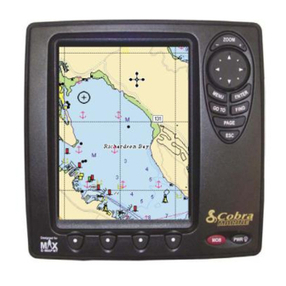
The GTD-110/150 series of Track Display system is a GPS based color electronic chart, designed for
navigational aids for small and medium size vessel. The GTD-110/150 Track Display system is
composed of a Display unit and a GPS antenna unit. General features of each unit are as follows:
Display unit: This unit uses a high brightness, TFT (Thin Film Transistor) Liquid Crystal Display (LCD)
to allow easy viewing in daytime and nighttime operations. Thanks to its wide viewing angle display,
you can observe the display from all possible positions in the wheelhouse. The screen size of the
display unit varies according to the type, i.e. 10.4 inch (Diagonal) for GTD-110 and 15 inch for GTD-150.
The panning and scrolling speed is greatly improved by using the latest digital technology. The
operation is simple and straightforward, using dedicated rotary controls and tactile key pads with
user-friendly menus. The display unit is a splash proof design, meeting IPX5 technical standard.
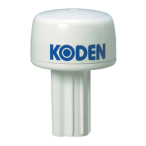
GPS antenna unit (Option): This unit includes the GPS antenna and its receiver section in a water
-sealed high grade plastic case.
1.3 Applicable standards
The GTD-110/150 series of Track Display complies with the requirements of the technical standards of
IEC-60945 (3rd edition).
1.4 Equipment composition
The equipment composition of GTD-110/150 is shown in Figure 1.1.
1.5 Software type name
The following software type is used in the GTD-110/150 Track Display system.
Software type Application
KMC-57 System control

GTD-110/150 Chapter 1
General Information
93151542-00 1-3
Figure 1.1 Configuration of GTD-110/150
Junction Box
JB-10
(Option)
CW-376
GPS Track Display
GTD-110/150
DGPS Sensor
(Option)
KBG-2(B type)
GPS Sensor
(Option)
GPS-10A(B type)
GPS Receiver
CW-373
CW-374
CW-375
CW-376
AC/DC Power Rectifier
PS-003A (Option)
10.8 - 31.2VDC
100/115VAC
200/230VAC
DC Power cable
CW-253
Color Fish Finder
CVS-108/118
CVS-832
CVS-8841/8842/8816
CVS-8851/8852
CVS-8826/8826 series
Marine Radar
MD-3420/3441
MD-3641/3642
MD-3840
MD-3010/3020/3050/3210
series
Marine Radar with ATA
MDC-721/741/740
MDC-1541/1540/1560/1510
/1520
MDC-1021/1041/1040
MDL-1121/1141/1140
Marine Radar with ATA
MD-3641/3642/3840
CW-381
CW-374
CW-374
CW-374
Color Fish Finder
CVS-842
CVS-852
CW-373
Color Fish Finder
CVS-108/118
CVS-832
CVS-8841/8842/8816
CVS-8851/8852
CVS-8826/8826S series
Marine Radar ゙
MD-3420/3441
MD-3641/3642
MD-3840
MD-3010/3020/3050/3210
series
Color Fish Finder
CVS-842
CVS-852
(Option)
(Option)
(Option)
(Option)
(Option)
(Option)
(Option)
Marine Radar with ATA
MD-3641/3642/3840
CW-154A
(Option)
CW-154A
CW-154A
CW-376
(Option)
(Option)
(Option)

GTD-110/150 Chapter 2
Equipment Composition
93151542-01 Contents
Chapter 2
Equipment Composition
Contents
Page No.
2.1 Standard Equipment list …………………………………… 2-1
2.2 Option items list ……………….……………………………. 2-1

GTD-110/150 Chapter 2
Equipment composition
93151542-01 2-1
Chapter 2 Equipment composition
2.1 Standard equipment list
No Item name Type name Remarks Weight/Length Q’ty
1 Display unit
GTD-110/150
With base mount and PVC
cover
6.5 kg/10 kg
1
2 DC power cable CW-253-2M
5 pin waterproof
connector/fly
leads with 10Afuse 2 m
1
3 Fuse F-7161
10 Amp
1
4 Operation manual
93151542-00
English
1
2.2 Optional items list
No Item name Type name Remarks Weight/
Length
1 GPS sensor GPS-10A For GPS position fixing with
power & signal cable connector 0.74 kg
10 m
2 DGPS sensor KBG-2 For DGPS positioning,
power & signal cable connector 1.6 kg
10 m
3 Connector
LTWD-06BFFA-L180
For NMEA-0183 -
4 GPS antenna holder RAH- 29 Ratchet mount -
5 Junction box JB-10 1 input 3 outputs X 2 circuits 0.4 kg
6 Connecting cable CW-373-5M 6 pin waterproof connectors (LTW)
both ends 5 m
7Connecting cable CW-374-5M 6 pin connector / 6 pin waterproof
connector (LTW) 5 m
8Connecting cable CW-375-5M 6 pin waterproof connector (Conxal)/
6 pin waterproof connector (LTW) 5 m
9Connecting cable CW-376-5M Fly leads /
6 pin waterproof connector (LTW) 5 m
10 Connecting cable CW-381-5M Half-pitched /
6 pin waterproof connector (LTW) 5 m
11 Connecting cable CW-60-10M For navigator unit junction box、
BNC / fly leads with crimping terminals 10 m
12 Connecting cable CW-154A-5M For navigator unit junction box、
6 pin connector / fly leads with
crimping terminals 5 m
13 Connecting cable CW-352-5M For navigator unit junction box、
6 pin waterproof connector (Conxall) /
fly leads with crimping terminals 5 m
14 Connecting cable CW-328-5M
For navigator unit junction box、
6 pin waterproof connector (Conxall) /
fly leads with crimping terminals with
ferrite core
5 m
15 AC / DC power rectifier PS-003A With 5A fuse (2 pcs) 2.8 kg
16 AC power cable VV-2D8-3M Fly leads both ends 3 m

GTD-110/150 Chapter 3
Specification
93151542-00 Contents
Chapter 3
Specification
Contents
Page No.
3.1 Specification ……..……….………………….……….…...…. 3-1
3.2 Serial data ……………………………….……………..…..… 3-1
3.3 Power requirements…..………………..……….…………… 3-2
3.4 Environmental conditions …………….….…….……….…… 3-2
3.5 External dimensions and weight ……..……………....……. 3-2

GTD-110/150 Chapter 3
Specification
93151542-00 3-1
Chapter 3 Specification
3.1 Specification Specification is subject to change without notice.
Type name GTD-110/150
Display 10.4 inch (GTD-110) / 15 inch (GTD-150)
High Brightness Color TFT LCD
Map mode Mercator projection
Display mode North-up, East-up, South-up, West-up, Course-up (Waypoint),
Head-up and Centered North-up
Track Zooming range 0.5 – 7,058 nm (1 – 13,072 km)
Effective map
creation area Below the latitude 80 degree
Time 1, 2, 5, 10, 20, 30, 60, 120, 300, 600 secPlotting
interval Distance 0.01, 0.02, 0.05, 0.1, 0.2, 0.5, 1.0, 2.0, 5.0, 10.0 nm (km)
No. of plots 2,000, 4,000, 7,000 (maximum plot) x 7 blocks
Display
Track color 7 colors
Position data display Lat/lon, Loran C LOP
Navigation data display Own ship’s position, Own ship’s course, Own ship’s speed,
Waypoint position, Waypoint bearing, Waypoint distance, POB
position, POB bearing, POB distance, Cursor position, Cursor
bearing, Cursor distance
Position registration 8,300 points (All points can be registered as waypoint)
Mark color 7 colors
Mark shape
(The marks are only useable in Mark Editing mode)
Chart used
C-Map NT
Graphics Drawing nodes 500 points x 7 blocks
Display color 7 colors
Route 50 points x 50 routes
Alarm Arrival, POB, Cross track error
Positional correction By cursor or by lat/long or LOP data
Magnetic compass correction Manual
Memory backup By Lithium battery (for SRAM backup) and Non-volatile ROM
Other functions Name, Loran C LOP, Ring markers
3.2 Serial data
[Input data]
Type:
NMEA-0183 Ver. 2.0/1.5
Sentence:
GGA, GLL, VTG, ZDA
、
RMC, MSS, MTW, TTM
[Output data]
Type:
NMEA-0183 Ver. 2.0
Sentence: APB, GGA
, GLL, VTG, XTE, ZDA, GTD

Chapter 3 GTD-110/150
Specification
3-2 93151542-00
3.3 Power requirements
Input voltage: 10.8 - 31.2 VDC
Power consumption: GTD-110: Less than 30 W (at 24VDC)
GTD-150: Less than 40 W (at 24VDC)
AC Operation: AC/DC rectifier P
S-003A is required.
Input voltage range:
115 VAC
or
230 VAC
3.4 Environmental conditions
(1) Temperature and humidity
Operating temperature:
-15
o
C - +55
o
C
Storage temperature: +70oC
Humidity:
93 ±3 % (at +40
o
C)
(2) Vibration
The equipment operates normally under the following vibrating conditions.
2 - 5 Hz - 13.2 Hz: Amplitude ±1mm ±10 % (Maximum acceleration of 7 m/s
2
at 13.2 Hz)
13.2 Hz - 60 Hz: Maximum acceleration of 7 m/s
2
being applied
(3) Water proof
Resistive against driven water, in compliance with IPX5
3.5 External dimensions and weight
External dimensions: Width x Height x Depth
GTD-110
GTD-150
Dimensions (WxHxD): 320 x 340 x 138 390 x 430 x 173 (mm)
Weight: 6.5 kg 10 kg
Refer to Figure 3.1 and Figure 3.3 for the exterior with dimensions.

GTD-110/150 Chapter 3
Specification
93151542-00 3-3
Unit:mm
Figure 3.1 The Exterior of GTD-110 with dimensions
Figure 3.2 Service space required for GTD-110
Unit in mm (inch)

Chapter 3 GTD-110/150
Specification
3-4 93151542-00
Unit in mm (inch)
Figure 3.3 The Exterior of GTD-150 with dimensions
Figure 3.4 Service space required for GTD-110
Other manuals for GTD-110
1
This manual suits for next models
1
Table of contents
Other Koden GPS manuals

Koden
Koden KGP-913 User manual

Koden
Koden GTD-110 User manual

Koden
Koden KGP-915 User manual

Koden
Koden GTD-120 User manual

Koden
Koden KGC-1 User manual

Koden
Koden MRE-280 User manual

Koden
Koden KGP-915 User manual

Koden
Koden KGP-920 User manual

Koden
Koden MDC-2000BB Series User manual

Koden
Koden PKP-27 User manual