Koden KGC-222 User manual


KGC-222 Revision History
0093822202-01 i
KGC-222 Service Manual
Doc No: 0093822202
Document Revision History
No. Doc. No-Rev. No. Date revised
(Y/M/D) Revised content
0 0093822202-00 2014/03/13 First edition
1 0093822202-01 2014/09/18 System Configuration, Chapter 2, Chapter 3
2
3
4
5
6
7
8
9
10
Document No. Revised Version Norm
When part of the document needs to be revised, the document has advanced revision number.
The document No. is indicated at the lower right side on the cover and at the left or right side
of the footer region of each page.
© 2014 Koden Electronics Co., Ltd. All rights reserved.
No part of this publication may be reproduced, transmitted, translated in any form by any
means without the written permission of Koden Electronics Co., Ltd. The technical
descriptions contained in this publication are subject to change without notice. Koden
assumes no responsibility for any errors, incidentals or consequential damages caused by
misinterpretation of the descriptions contained in this publication.

Important Notice KGC-222
ii 0093822202-01
Important Notice
For copy and transcription of this Service Manual (hereinafter referred to as this manual),
permission from Koden is needed. Koden prohibits the un-authorized copy and
transcription of this manual.
If this manual is lost or damaged, consult a dealer of Koden or Koden.
The specification of the products and the contents in this manual are subject to change
without notice.
The contents displayed on the menu of product may be different from the expression of
this manual. The fonts and shapes of the keys and menus in the illustration may differ
from the actual ones, and some parts may be omitted.
Koden is not liable for damages and troubles arisen from misunderstanding of the
contents in this manual.
Koden is not liable for any damages caused by earthquake, lightning, wind and flood
damage and fire for which Koden is not responsible, and actions by third parties, other
accidents, customer’s unintended error/abuse and the use under other abnormal
conditions.
Koden is not liable for damages of accompaniment (change/loss of memorized content,
loss of business profit, stop of business) arisen from use or failure of our products.
If the stored data are changed or lost, irrespective of causes of troubles and damages,
Koden is not liable for them.
Koden is not liable for any damages arisen from malfunction caused by combination of
software and connected equipment in which Koden is not engaged.

KGC-222 For Your Safe Operation
0093822202-01 iii
For Your Safe Operation
Pictograms used in this Service Manual
The following pictograms are used in this manual. The meaning of each symbols shall be well
understood and the maintenance and inspection shall be carried out.
Symbol Meaning
Mark for warning
This mark denotes that there is a risk of death or serious injury when
dealt with incorrectly.
Mark for danger of high voltage
This mark denotes that there is a risk of death or serious injury due to
electric shock when dealt with incorrectly.
Mark for caution
This mark denotes that there is a risk of slight injury or damages of
devices when dealt with incorrectly.
Mark for prohibition
This mark denotes prohibition of specified conducts. Description of the
prohibition is displayed near the mark.
Precautions on equipment
Be careful of high voltage inside
High voltage, which may risk you life, is used. This high voltage may
remain in the circuit even after the power is switched off. To prevent
contact with the high voltage circuits accidentally, a protective cover or
the label with this mark is provided on the high voltage circuit. When the
inside is to be checked, ensure to switch off the power and to discharge
the residual voltage for safety. An engineer authorized by Koden shall
carry out the inspection and maintenance works.
Power off in the boat
An accidental power-on during works may result in worker’s
electrification. To prevent such accident in advance, ensure that power
in the boat and on the equipment are switched off. Furthermore, it is
safer to hang a caution tag saying “Under work” near the power switch
of equipment.
Be careful of dust
Inhaled dust may cause respiratory affection. At the time of cleaning the
inside of equipment, be careful not to inhale dust. Wearing a safety
mask is recommended.
Caution on location of installment
The equipment shall not be installed at locations which are excessively
damp and suffers from water drops. Otherwise, dew condensation may
occur inside the display screen, and corrosion may occur inside the unit
box.
Warning
Warning
Caution
Warning
Caution

For Your Safe Operation KGC-222
iv 0093822202-01
Measures against static electricity
Static electricity may be generated from the carpet on the floor in the
cabin or clothes made of synthetic fiber, and it may destroy the
electronic components on circuit boards. The circuit boards shall be
handled with appropriate measures against static electricity.
Caution at installation o
f
transduce
r
Transducer shall be installed at locations where there is no effect by
bubble and noise. Bubble and noise may seriously degrade the
performance of this equipment.
Precautions on handling
No disassembly or modification of this equipment is allowed. It may lead
to failure, firing, smoking or electric shock. In case of failure, please
contact Koden’s dealers or Koden.
In case of smoking or firing, switch off the power in the boat and of this
equipment. It may lead to firing, electric shock or damages.
Be careful of residual high voltage
High voltage may remain in capacitors for several minutes after
switching off the power. Before inspection of the inside, please wait at
least 5 minutes after switching off or discharge the residual electricity in
an appropriate manner. Then, start the work.
The information displayed on this equipment is not intended to use for
your navigation. For your navigation, be sure to see the specified
materials.
Please use the specified fuses. If un-specified fuses are used, they may
cause firing, smoking or damages.
Be sure to submerge the transducer in water before transmission. If
not, it may be damaged.
Caution
Caution
Warning
Warning
Caution
Caution
Caution

KGC-222 Contents
0093822202-01 v
Contents
Document Revision History .............................................................................................. i
Important Notice .............................................................................................................. ii
For Your Safe Operation................................................................................................. iii
Contents ........................................................................................................................ v
Introduction.................................................................................................................... vii
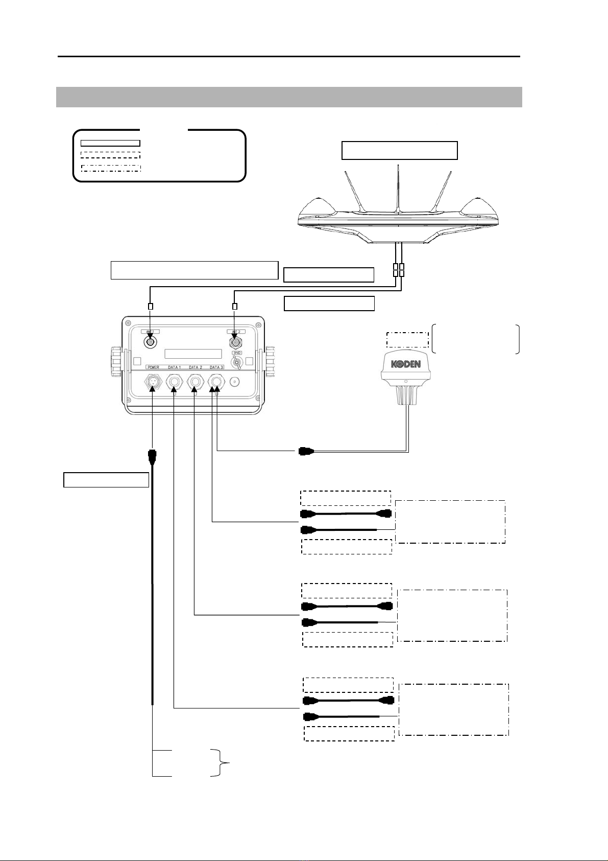
System Configuration ....................................................................................................viii
System Configuration (with Junction box) ...................................................................... ix
Pin Assignment of Rear Connector ................................................................................. x
Connection with Junction box (JB-35) ............................................................................ xi
Configuration of Equipment ........................................................................................... xii
External view and dimensions ...................................................................................... xiv
Specifications ............................................................................................................... xvi
Chapter 1 Installation .......................................................................... 1-1
1.1 Items of Caution on Installation............................................................................1-1
Unpacking the components ................................................................................ 1-1
Appearance varification of each unit and accessories........................................ 1-1
Selection of location for installation .................................................................... 1-1
Laying and Connection of Cable ........................................................................ 1-3
Confirmation after Installation............................................................................. 1-4
1.2 Installation of Display unit ....................................................................................1-5
Table mounting ................................................................................................... 1-5
Flush mounting................................................................................................... 1-6
1.3 Installation of GPS antenna GA-12......................................................................1-7
Antenna cable layout method............................................................................. 1-7
Installation of GPS antenna................................................................................ 1-8
Angle compensation of Antenna......................................................................... 1-9
Connecting and waterproofing the connector..................................................... 1-9
Connecting the 60m antenna cable kit CW-394.KIT to GPS antenna .............. 1-10
Installing the bird protector to Antenna unit .......................................................1-11
1.4 Wiring.................................................................................................................1-12
Chapter 2 Maintenance and Troubleshooting ..................................... 2-1
2.1 Inspection ...............................................................................................................2-1
2.2 Cleaning .................................................................................................................2-1
Display unit......................................................................................................... 2-1
2.3 If you suspect a trouble ..........................................................................................2-1
2.4 Error Message........................................................................................................2-2
2.5 Initialize ..................................................................................................................2-4

Contents KGC-222
vi 0093822202-01
Initialization of KGC-222 is performed. ...............................................................2-4
Chapter 3 Detail of the serial output data ............................................ 3-1
3.1 Output data format............................................................................................... 3-1
3.2 Details of the output data format.......................................................................... 3-1
3.3 Output data specification .....................................................................................3-1
3.4 Details of output sentences .................................................................................3-1
Chapter 4 Technical references........................................................... 4-1
4.1 Maintenance parts list.......................................................................................... 4-1
4.2 Exploded view drawing........................................................................................ 4-2
4.3 Block diagram...................................................................................................... 4-3

KGC-222 Introduction
0093822202-01 vii
Introduction
KGC-222 is a GPS compass.
Through the use of GPS satellites, it outputs the heading of vessel with a high degree of
accuracy by calibrating the phase difference of two GPS antennas.
The main features of this unit are as follows:
KGC-222 consists of two main components, Display and Antenna.
Display unit has processor, receiver and LCD display built-in.
KGC-222 has internal electronic compass as backup sensor.
This enables the backup sensor to output heading even if the GPS signals are interrupted
in such case as the vessel passing under a bridge.
KGC-222 can also output pitch / roll and heaving data.
When KGC-222 is used with an echo sounder with heaving compensation function, you
can obtain stable sea bottom without effect from heaves and waves.
It has 3 heading data output ports. Up to 5 ports will be available with connecting an
optional junction box.

SystemConfiguration KGC-222
viii 0093822202-01
System Configuration
Connection diagram
緊急
Display unit KGC-222
With mounting bracket and vinyl cover
Red +
Black -
10.8 to 31.2VDC
GPS antenna GA-12
With Bird protector
Chart Plotter
Echo sounder
DATA 3 Connector
CW-373-5M
CW-376-5M
Marine radar
Chart Plotter
Echo sounder
Auto pilot
DATA 2 Connector
CW-373-5M
CW-376-5M
Marine radar
Chart Plotter
Echo sounder
Auto pilot
DATA 1 Connector
CW-373-5M
CW-376-5M
CW-392-15M
CW-392-15M
CW-266-1.8M
Owner supply
Option
Standard configuration
Legend
DATA 3 Connector
KBG-3
Software virsion:
KM-E34G and after
is required.
POWER Connector

KGC-222 SystemConfiguration
0093822202-01 ix
System Configuration (with Junction box)
Connection diagram
緊急
Display unit KGC-222
With mounting bracket and vinyl cover
Red +
Black -
10.8 to 31.2VDC
GPS Antenna GA-12
With Bird protector
DATA 2 Connector
Marine radar
Chart Plotter
Echo sounder
Auto pilot
CW-373-5M
CW-376-5M
DATA 4 Connector
DATA 1 Connector
CW-392-15M
CW-392-15M
CW-266-1.8M
Owner supply
Option
Standard configuration
Legend
DATA 3 Connector
DATA 5 Connector
Junction Box
JB-35
Marine radar
Chart Plotter
Echo sounder
Auto pilot
CW-376-5M
Marine radar
Chart Plotter
Echo sounder
Auto pilot
CW-376-5M
Marine radar
Chart Plotter
Echo sounder
Auto pilot
CW-376-5M
DATA 3 Connector
Chart Plotter
Echo sounder
CW-373-5M
CW-376-5M
CW-376-5M
KBG-3
POWER Connector
Software virsion:
KM-E34G and after
is required.

SystemConfiguration KGC-222
x 0093822202-01
Pin Assignment of Rear Connector
The pin assignment is viewed from the rear of the Display unit.
For reference:
Connector acceptable: LTWBD-06BFFA-L18
Wire color of CW-376-5M
1 Blue+Shield
2 White
3 Red
4 Orange
5 Black
6 Green
Caution: The maximum current capacity
is 300 mA in total, then it should not
exceed.
Take care that the grand total of each
connector does not exceed 300 mA.
Caution: KGC-222 Compass has 12V power on PIN 6 of each DATA connector.
Please pay attention not to accidentally connect 12V to other equipment
NMEA input. Equipment damage may occur.
1 3
2
1 POWER+
2 F.GND
3 POWER-
POWER
Power Input
1 GND
2 TX+
3 TX-
4 RX+
5 RX-
6 +12V (Maximum 300 mA)
DATA1/2/3
DATA IN/OUT
4
5
1
3
2 6

KGC-222 SystemConfiguration
0093822202-01 xi
Connection with Junction box (JB-35)
To extend the ports, connect the junction box (JB-35) to the data connectors as shown in the
figure below.
Set the DIP switch (S1) as shown in the figure below.
Wire the cables with the CW-376-5M (option) as shown in the following color chart.
CW-376-5M
To DATA1 of Display unit
SLAVE1
SLAVE3
MASTER
SLAVE2
Green
Black
Orange
Red
White
Blue+Shield
+12V
TX-
TX+
RX-
RX+
GND
Green
Black
Orange
Red
White
Blue+Shield
NC
TX-
TX+
RX-
RX+
GND
S1
ALL OFF
To connection equipment
A
ssi
g
ned to DATA4
To connection equipment
A
ssi
g
ned to DATA5
A
ssigned to DATA1
To external equipment
JB-35
Green
Black
Orange
Red
White
Blue+Shield
NC
TX-
TX+
RX-
RX+
GND
Green
Black
Orange
Red
White
Blue+Shield
NC
TX-
TX+
RX-
RX+
GND
ON OFF
1 2 3 4 5 6 7 8

ConfigurationofEquipment KGC-222
xii 0093822202-01
Configuration of Equipment
Standard Equipment Configuration List
No. Name of item Type Remark Weight/
Length Qty
1 Display unit KGC-222.MU
With mounting bracket and
vinyl cover
0.87 kg 1
2 DC power cable
CW-266-1.8M With a 3-pin connector and one
end plain
1.8m 1
3 GPS antenna
G
A
-12 With bird protecto
r
1
4
A
ntenna cable
CW-392-15M 3D-2V
With BNC connectors on the
both sides
15m 2
5 Installation
material
TPT5 X 20U
T.5X20MMX10M
10M [gray]
B8X25U
Truss tapping screw (2)
Self-bonding tape (1)
PVC tape (1)
Hexagon bolt for antenna
installation (4)
1
set
6 Operation Manual KGC-222.OM.E English 1
7 Cautionary Note KGC-222.RM.E English 1

KGC-222 ConfigurationofEquipment
0093822202-01 xiii
Option List
No. Name of Item Specification Remark Weight/
Length
1 Connecting
cable
CW-373-5M 6P water resistant connecto
r
s at both
ends
5m
2 CW-376-5M With 6P water resistant connecto
r
and one end plain
5m
3 Junction box JB-35 1 input, 3 outputs with CW-376-5M
4 Power
r
ectifie
r
PS-010 With 5A fuses 2pcs 3.5kg
5
A
C power
cable
VV-2D8-3M Without connecto
r
s on the both sides
(cable for PS-010)
3m
6 Flush mount kit FMK-1 Flush mount frame with bolts,
washers and screws
7
A
ntenna cable
extension kit
CW-393-30M 5D-FB cable with BNC connecto
r
s at
both ends (2cables/1 unit)
30m
8 CW-394-60M KIT 8D-SFA cable with N connector and
other end plain, N connector, and
CW-826-0.5M (2sets/1 unit)
60m
9 Connecto
r
LTWBD-06BFF
A
-L1
80
6P water resistant connecto
r
10 Mount base D86MB21110 For Antenna (G
A
-12) 1
11
A
ttachment D86MB21120 Conversion metal attachment
(Switching the mounting holes of
GA11 to GA12)
1

External view and dimensions KGC-222
xiv 0093822202-01
External view and dimensions
Display unit: KGC-222.MU
Front view
Side view
Rear view
Weight: 0.89kg (With mounting bracket)
Unit: mm (inch)

KGC-222 External view and dimensions
0093822202-01 xv
GPS antenna: GA-12
Weight: 2.2kg (With antenna cables)
Unit: mm (inch)

Specifications KGC-222
xvi 0093822202-01
Specifications
Model Display unit : KGC-222.MU
GPSantenna : GA-12
Receiving frequency 1575.42MKz±1MHz
Receiving channel Parallel 16 channel
Sensitivity Better than -130 dBm
Setting time 2 minutes (at standard hot-start time)
Heading accuracy 1° rms
Heading resolution 0.1°
Maximum rate of turn 45°/s
Maximum follow-up
acceleration 1g
Maximum role / pitch
angle 30°
Base line length 0.5m
Time to position fix
Cold start
Warm start
Hot start
50 sec (standard)
45 sec (standard)
20 sec (standard)
Positioning accuracy
Position
Velocity
GPS: 10m (2 drms, SA:OFF, PDOP: 3 or less)
DGPS: 3m (2 drms, SA:OFF, PDOP: 3 or less)
1 m / sec (rms, SA:OFF, PDOP: 3 or less)
Datum 88 (WGS-84, Tokyo etc.)
Output data port 3 (standard), 5 (with connecting an optional junction box)
Output data
Format
Heading data sentence
Navigation data sentence
Datalevel
Output current
Output interval
NMEA 0183 Ver2.0
ATT, HDM, HDT, HVE, ROT, PKODG,21
DTM, GGA, GLL, GSA, GSV, MSS, RMC, VTG, ZDA, PKODA,
PKODG,1, PKODG,7, PKODQ
RS-422
20mA
20ms, 40ms, 50ms, 100ms, 200ms, 1s
Power supply 10.8 to 31.2VDC
Power Consumption 9W or less (at 24 VDC)
Operating temperature -15°C to +55°C
Water protection
Display unit
GPS antenna
IPX4
IPX6
Store temperature -30°C to +70°C
Upper limit of humidity 93% +/- 3% @ +40°C

KGC-222 Chapter 1 Installation
0093822202-01 1-1
Chapter 1 Installation
1.1 Items of Caution on Installation
In order to obtain the maximum performance of the GPS compass, this compass should be
installed by a qualified technician. Installation procedures include the following:
(1) Unpacking the components
(2) Inspection of configuration unit, spare parts, accessories and installation materials
(3) Checking of supply voltage and current capacity
(4) Selection of installation location
(5) Installation of Display unit and Antenna
(6) Attachment of accessories
(7) Planing and implementation of cable layout and connection
(8) Coordinataion after installation
Unpacking the components
Unpack components and check that all of the items correspond with the contents discription of
the packing list. When a discrepancy or damage has been found, contact the dealer you
purchased this product.
Appearance varification of each unit and accessories
Inspect the appearance of each components and accessories and check that no dents or
damage exist.
If any dents or damages exist and they are believed to be caused by accident during
transportation, contact the transportation and insurance company and consult our sales
company or our dealer nearest to you.
Selection of location for installation
In order to obtain the maximum performance of the unit, it is necessary to install following
below recommendations.
1. Display unit of KGC-222
(1) Install the display in the bridge where it will be easy to see and read.
(2) Choose the best location from humidity, spray, rain and direct sunlight.
(3) Keep safety distance from magnetic objects such as magnetic compasses.
(4) Keep sufficient maintenance space around the equipment, pay attention to the back of
the display where cables are connected.
(5) Keep the equipment as far away from wireless transmitter/receivers as possible.

Chapter 1 Installation KGC-222
1-2 0093822202-01
2. GPS antenna: GA-12
To operate the equipment in good order, the following points should be observed for
installation of GPS antenna.
The GPS antenna GA-12 must be installed where good radio wave reception is achieved. No
obstacles should be located above the antenna otherwise the radio wave reception may be
interrupted. This causes the available GPS service hours to be reduced and degrades the
positioning accuracy.
(1) Select a site away from metallic objects, where possible.
(2) Locate the GPS antenna at least 4 m away from radio antennas such as, Inverted-L
antennas for MF/HF transmission, Whip Antennas for VHF or UHF.
(3) Locate the GPS antenna at least 1.5 m above any Inverted-L antenna for MF/HF
transmission.
(4) Locate the GPS antenna at least 1 m from receiving antennas.
(5) Locate the GPS antenna away from radar beams (Vertical beam width: 30oto 40o).
(6) Locate the GPS antenna at least 1 m away from radar antennas.
(7) Locate the GPS antenna at least 5 m away from Inmarsat radomes.
(8) Locate the GPS antenna at least 3 m away from DF loop antennas.
(9) Locate the GPS antenna at least 2 m away from the ship’s engine.
(10) Locate the GPS antenna at least 0.5 m away from metallic objects.
Should any of the requirements mentioned in item (1) to item (10) not be met, try to fulfill the
requirements of item (10) and install the GPS Antenna as far as possible from the antennas
described in item (1) to item (9). Put the GPS Antenna as trial on a promising site to make
sure that the unit operates as specified before fixing the GPS Antenna position and then fix
the antenna firmly. The GPS Antenna installed in an improper site may result in poor bearing
accuracy and positioning error that may lead to potential hazards.

KGC-222 Chapter 1 Installation
0093822202-01 1-3
Laying and Connection of Cable
(1) Keep the antenna cable and power cable as far away from the cables of other electronic
equipment as possible.
(2) The cabinet of Display unit shall be securely grounded to the hull, using the ground
terminal on the rear panel.
(3) If you connect the power cable directly to the battery, the interference from other
electronic equipment is expected to be less. (See Fig. 1.1.)
Fig. 1.1 Connection of Power Line
Good example Bad example
Display unit Display unit
Battery Battery
Noise Noise
KGC-222 KGC-222
VHF Whip Antenna
Loop Antenna
Receiving Whip Antenna
HF Whip Antenna
NOTE: Keep away from metallic objects at least 0.5 m.
MF/HF Inverted-L
Antenna
Radar beam
See NOTE
5 m or more
3 m or more
1 m or more
Avoid radar beam illumination
(30oto 40o)
Inmarsat Antenna
4 m or more
4 m or more
1 m or more
1.5 m or more
4 m or more
GA-12
[Scale differs among drawings.]
Other manuals for KGC-222
1
Table of contents
Other Koden Marine GPS System manuals