X904647 Ver.1.0
Owner's Manual
Air Gun Type Ionizer [DTY-ELG41]
Thank you for purchasing the DTY-ELG41. This product is not specified to electric equipment
standards as a high-voltage device, but it does handle high AC voltages of approximately 2,500 V or
more. Please be sure to read this instruction manual before using the product, so that you can fully
understand its functions.
In addition, keep this manual in a safe place.
1. Safety precautions
High voltages are used inside this product, such that incorrect usage could lead to personal injury or
damage to the product. Koganei bears no responsibility if the product is used outside its specifications
or if the safety precautions are not observed.
DANGER
Expresses situations that can be clearly predicted as dangerous. If the
noted danger is not avoided, it could result in death or serious injury.
It could also result in damage or destruction of assets.
WARNING
Expresses situations that, while not immediately dangerous, could
become dangerous. If the noted danger is not avoided, it could result in
death or serious injury.
It could also result in damage or destruction of assets.
CAUTION
Expresses situations that, while not immediately dangerous, could
become dangerous. If the noted danger is not avoided, it could result in
light or semi-serious injury.
It could also result in damage or destruction of assets.
ATTENTION
While there is little chance of injury, this content refers to points that
should be observed for appropriate use of the product.
1.1 Danger
Do not use in locations where explosives, flammables, or other dangerous substances are present.
This product is not an explosion-proof type unit. Explosion or ignition may occur.
When any wiring, installation, or inspection work is to be carried out, make sure that the unit is
disconnected from the power supply, otherwise, an accident, an electrical shock or a malfunction
may be caused.
Never attempt to remodel the product. It could result in abnormal operation leading to injury, electric
shock, fire, etc.
Do not splash water on the product. Spraying it with water, washing it, or using it underwater could
result in malfunction of the product leading to injury, electric shock, fire, etc.
High voltages are applied to the discharge needle, so do not put it near electrically conductive
materials, such as your fingers, body, wires, or tools. Doing so could result in electric shock or
malfunction.
1.2 Warning
Do not use the product in excess of its specification range. Doing so creates the risk of product
breakdown, loss of function, or damage. It could also drastically reduce the operating life.
The tip of the discharge needle is sharp, so be careful when handling it. This could result in
personal injury.
Always supply compressed air before supplying electric power. Supplying electric power while no
compressed air is supplied may result in a discharge that increases internal ozone density that
produces a bad effect on the devices and environment.
When using the product, do not point the nozzle at people, especially their face or eyes, etc. This
could result in personal injury.
Cables that are damaged by being bent excessively, pulled, rolled up, placed under heavy objects,
or squeezed between two objects create the risk of current leaks or defective continuity that could
result in fire, electric shock, or abnormal operation.
1.3 Caution
The ionizer generates ozone while exposed to the atmosphere. If you are using only one ionizer,
the density will not saturate and rise above a set point. However, if multiple units are being used
and you smell ozone, ventilate the area. Also, do not place your face near the nozzle of the ion
air blower to confirm the smell of ozone. Your nose and throat could become sore.
1.4 Attention
Equipment and parts used near the ionizer (especially ones with low ozone resistance such as NBR)
should be checked periodically for ozone degradation.
When the product can no longer be used or is no longer necessary, dispose of the consumables
appropriately as industrial waste.
Do not wire parallel to power lines or high-voltage lines. Inductive noise could cause erratic operation.
*Regarding dangers, warnings, and cautions not noted above, refer to the “Safety Precautions
(Common to All Ionizers) and Handling Instructions and Precautions (Common Precautions)” in the
Static Electricity Removal Unit Ionizers catalog.
(Be sure to refer to the most recent catalog.)
2. Contents of the product set
When you receive this product, before you use it, check whether there are any missing items, and
whether there were any abnormalities or damages that occurred during shipping. If there are damages,
or if the product does not operate normally, contact your retailer (agent) or our nearest sales office.
· Main unit…1, · Nozzle*…1, · Discharge needle*…1, · AC adaptor…1,
· Owner’s Manual (this manual)…1
*The main unit is installed when shipped.
3. Static charge elimination characteristics
The product’s static charge elimination characteristics are shown below.
(DTY-ELG41)
(DTY-ELG41-PAU)
(*Under Koganei measurement conditions)
* Measurement distance : 50 mm
* Measuring device :
Charged plate monitor (plate size 150 mm x 150 mm, electrostatic capacitance 20 pF)
* Static charge elimination time : Attenuation time from ±1000 V to 100 V
* Φ6 air fitting, Φ6 air tube
4. Specifications
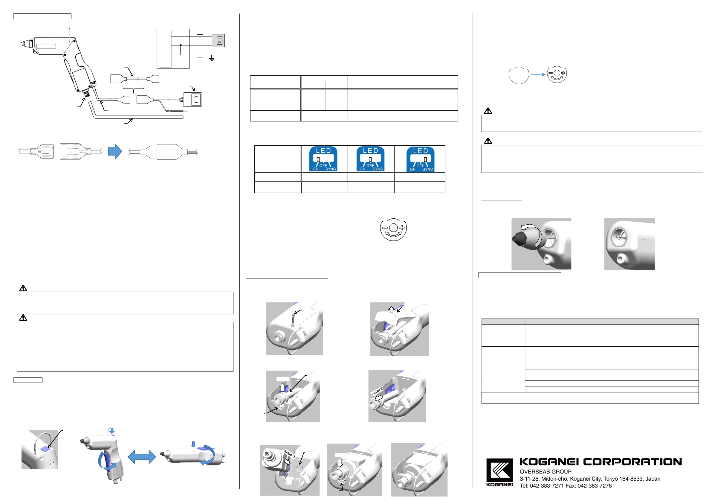
Names of parts
[When gun shaped DTY-ELG41-PAU]
[When straight]
[When straight DTY-ELG41-PAU]
Specifications
Model number DTY-ELG41 DTY-ELG41-PAU
Ion production method High-frequency corona discharge
Power supply voltage Provided AC adaptor INPUT: AC100 - 240 V, 50/60 Hz, 0.3 A
(OUTPUT: DC 24 V, 0.5 A)
Product input voltage DC24 V ± 5%
Consumption current Less than 100 mA
Output voltage 2,500V
Ion balance ±15V *
Medium used Air (clean air that contains no moisture or oil)
Operating air pressure range 0.05 - 0.6MPa 0.2 - 0.6MPa
Air flow rate Maximum 370 ℓ/min (ANR) Maximum pulse flow rate 120
ℓ/min (ANR)
Dimensions of main unit
(excluding protrusions)
Gun-shaped: 177.3 (L)×32 (W)×127.9 (H)
Straight: 222.2 (L)×32 (W)×50 (H)
Weight Approximately 185g
(cable not included)
Approximately 235 g
(cable not included)
Pulse blow - Frequency of pulse blow 5 Hz to
15 Hz *
Usage environment Indoors, altitude of 2000 m or less, pollution degree 2 (according
to IEC61010-1)
Temperature in usage environment
0 - 40ºC
Humidity in usage environment 65% or less (Non-condensation)
Indicators Green: indicates power/discharging; red: indicates abnormal display
Lighting LED for lighting (white)
Switch for LED lighting Switch for LED lighting (3 positions)
Always off/always on/synced to lever
Amount of ozone generated 0.04 ppm or less (when 200 mm from tip of nozzle, 0.2 MPa air pressure)*
Material Main unit: PBT, nozzle: PPS
*Under Koganei measurement conditions.
5. Wiring and Piping
WARNING
● Always supply air to the product whenever it is turned on. Furthermore, when using the product
adjust the air flow rate to be 60 ℓ/min (ANR) or more.
● Do not remove and replace the air fitting on the main unit. Doing so could result in damage to the
main unit.
CAUTION
● Do not install the product where it could be splashed by water or oil; locations where condensation
forms easily; or locations exposed to severe changes in temperature or humidity. Doing so could
damage the product.
● Be sure to use the dedicated AC adaptor. Otherwise, the product could break down, its functions
could stop, or it could be damaged.
● Use clean air, from which oil and moisture have been removed, as the medium. Using air that
contains water or oil could result in the nozzle and interior of the main unit becoming dirty, the
static discharge performance falling, or the main unit deteriorating.
Installation
Hold the product in your hand and use it the same way as a regular air gun. Also, the main unit can
be hung by its suspension bracket.
The suspension bracket can be moved for hanging while either straight or gun-shaped. Change the
position of the suspension bracket according to your application.
To remove the suspension bracket, pull it open from both sides as shown in figure 1.
[When gun-shaped] [When straight]
Figure 1
Air pressure [MPa]
0.1
0.2
0.3
0.4
0.5
0.6
+Static charge elimination time [seconds]
0.3
0.2
0.3
0.2
0.2
0.1
-Static charge elimination time [seconds]
0.3
0.2
0.3
0.2
0.2
0.1
Flow rate [L/m (A.N.R.)]
99
159
215
266
320
370
Air pressure [MPa] 0.2 0.3 0.4 0.5 0.6
+Static charge elimination time [seconds] 0.6 0.4 0.4 0.3 0.3
-Static charge elimination time [seconds] 0.6 0.4 0.4 0.3 0.3
Flow rate [L/m (A.N.R.)] 56 79 102 113 118
Lever
Nozzle
bracket
Φ6 air fitting*1
Power cable (2 m)
LED
Lock button
LED
lighting
Trimmer to adjust frequency
of pulse blow*2
*2 Covered by label on DTY-ELG41.
LED
lighting
Lever
Nozzle
bracket
Φ6 air fitting*1
Power cable
(2m)
Indicator LED
Lock button
LED
lighting
Trimmer to adjust
frequency of pulse blow*2
Switch for
LED lighting
Cover
Cover
*1 For DTY-ELG41
Φ6 air fitting