Kohler Salute User manual

1
KOHLER SALUTE
Installation and User Guide
THERMOSTATIC MIXER
These instructions must be left with the user.

2
CONTENTS
Introduction .............................................................................................3
Patents and Design Registration..........................................................3
Safety : Warnings ....................................................................................3
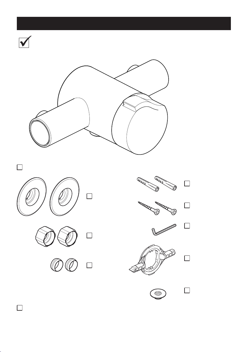
Pack Contents .........................................................................................4
Dimensions ..............................................................................................5
Specications ..........................................................................................5
Pressures ............................................................................................. 5
Temperatures .......................................................................................5
Thermostatic Shut-down ......................................................................6
Flow Rates ...........................................................................................6
Connections .........................................................................................6
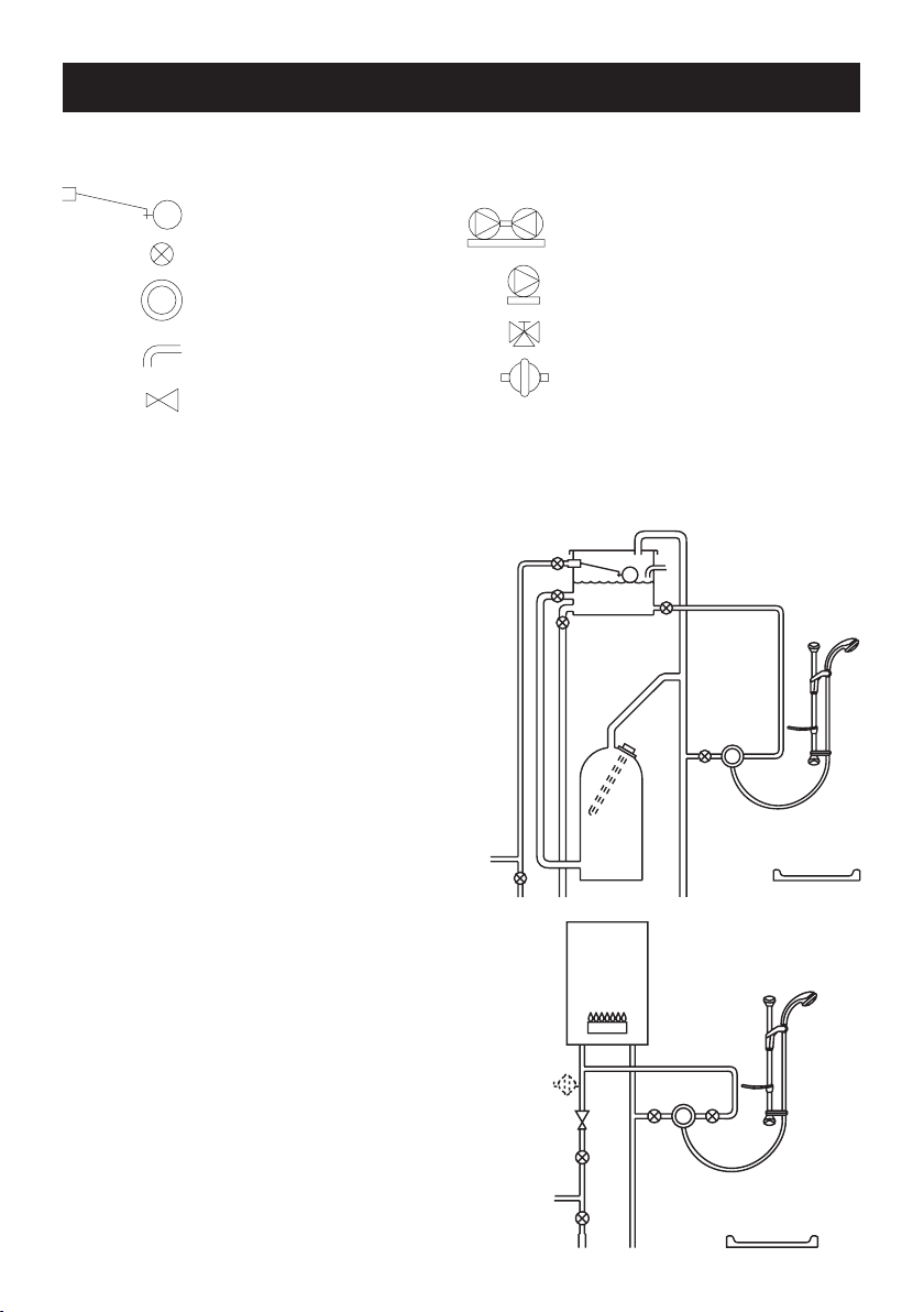
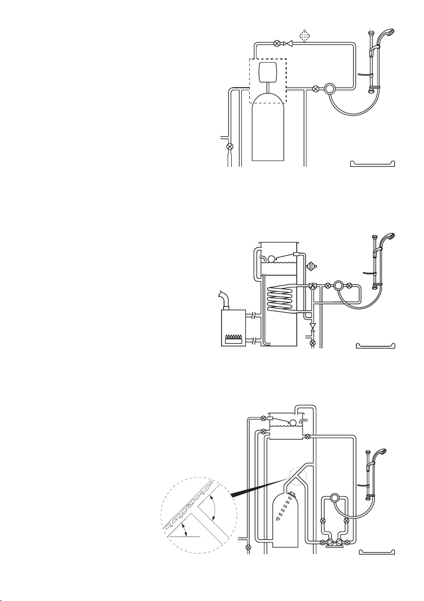
Installation Requirements ......................................................................7
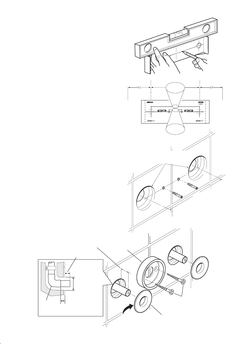
Installation ...............................................................................................9
General.................................................................................................9
1. Rear Entry Supplies (rising or falling concealed pipework)............ 10
2. Rising or Falling Supplies...............................................................12
Reversed Inlet Supplies........................................................................14
Commissioning .....................................................................................15
Maximum Temperature Setting ..........................................................15
Operation ...............................................................................................16
Fault Diagnosis......................................................................................17
Maintenance...........................................................................................18
General...............................................................................................18
Inlet Filters..........................................................................................19
Type 2 Valves .........................................................................................21
Spare Parts ............................................................................................22
Customer Service....................................................................Back Page
If you experience any difculty with the installation or operation of your new
Thermostatic Mixer, please refer to ‘Fault Diagnosis’, before contacting Kohler Mira
Ltd. Our telephone and fax numbers can be found on the back cover of this guide.

3
INTRODUCTION
SAFETY : WARNINGS
This Kohler Salute Thermostatic Mixer is precision engineered and should give
continued safe and controlled performance, provided:
1. It is installed, commissioned, operated and maintained in accordance with
manufacturers recommendations.
2. Periodic attention is given, when necessary, to maintain the product in good
functional order.
Thank you for purchasing a quality Kohler product. To enjoy the full potential of your
new product, please take time to read this guide thoroughly, having done so, keep
it handy for future reference.
The Kohler Salute Thermostatic Mixer is a Thermostatic Shower Control with a
Single Sequential Knob for on/off and temperature control. It has been designed to
compliment the Kohler Salute Brassware range.
The Thermostatic Mixer incorporates a Wax Capsule Temperature Sensing Unit. This
provides an almost immediate response to changes in pressures or temperature of
the incoming water supplies to maintain the selected temperature. An adjustable
Maximum Temperature Stop is provided which limits the temperature to the desired
level. Inlet Filters are tted to protect the Thermostatic Cartridge.
The Kohler Salute Thermostatic Mixer is an exposed Shower Control for connection
to wall mounted or rear entry pipework at centres of 153 mm.
This product has been certied as a Type 2 valve under the BUILDCERT TMV2
scheme. This product also complies with the Water Supply (water ttings) Regulations
1999.
Patents and Design Registration
Design Registration: 000555768-0004, 000555768-0005
Patents: GB: 2 291 693, 2 392 225, 2 421 297
Germany: 695 13 455.8
France: 0 694 721 (E)
Patent Applications: Euro: 1 672 257, 03254070.0
USA: 2006-0124758-A1, 10/607 025

4
PACK CONTENTS
Tick the appropriate boxes to familiarize yourself with the part names and to
conrm that the parts are included.
1 x Kohler Salute Thermostatic Mixer
1 x ‘O’ Key
2 x Olives
2 x Compression
Nuts
2 x Concealing
Plates
1 x 2.5 mm
Hexagon Key
2 x No 8 x 1 ¼”
Securing Screws
2 x Wall Plugs
Documentation
1 x Installation Template
1 x 12 L/Min
Flow Regulator

5
DIMENSIONS
200 mm 117 mm
35 mm153 mm (Pipe Centres)
For Type 2 Valves, the supply conditions specied in section: ‘Type 2 Valves -
Application’ take precedence over the operating parameters which follow.
Pressures
Maximum Static Pressure: 10 Bar.
Minimum Maintained Pressure (Gas Water Heater): 1.0 Bar.
(for optimum performance supplies should be nominally equal).
Minimum Maintained Pressure (Gravity System): 0.1 Bar.
(0.1 bar = 1 Metre head from base of cold tank to the outlet of the
shower handset).
Maximum Maintained Pressure: 5 Bar.
Temperatures
Factory Pre-set (Blend) Shower: 43°C.
Optimum Thermostatic Control Range: 35°C - 45°C.
(Achieved with supplies of 15°C cold, 65°C hot and nominally equal
pressures).
Maximum Hot Supply: 85°C.
Recommended Hot Supply: 60°C - 65°C.
Minimum Differential between Hot Supply and Outlet Temperature: 10°C.
Cold Water Range: 5°C - 25°C.
SPECIFICATIONS

6
Thermostatic Shut-down
Thermostat will shut off Hot Supply Within 2 Seconds if Cold Supply Fails.
(Achieved only if the hot supply temperature is greater than 10°C above the set
blend temperature).
Flow Rates
Typical Flow Rates (Valve Only)
Connections
Standard connections are: Hot-Left, Cold-Right, Bottom-Outlet. If reversed inlets
are required refer to section: ‘Reversed Inlet Supplies’.
Inlets: 15 mm Compression.
Outlet: ½” BSP.
Low Pressure - No Flow Regulator Fitted
High Pressure - 12 L/Min Flow Regulator Fitted
5
10
15
20
25
30
35
0
0
Pressure Loss (bar)
Flow Rate (L/Min)
1.0 2.0 3.0 4.0 5.0

7
INSTALLATION REQUIREMENTS
Isolating Valve
Thermostatic Mixer
Overow Indicator
Pressure Reducing Valve
Float Valve Twin Impeller Pump
Single Impeller Pump
Tempering Valve
Mini Expansion Vessel
Key to Symbols
The Kohler Salute Thermostatic Mixer is compatible with the following systems:
Gravity fed system
The Thermostatic Mixer MUST be fed from
a cold water cistern and hot water cylinder
providing nominally equal pressure.
Gas heated system
The Thermostatic Mixer MUST be installed
with a gas water heater or combination
boiler of a fully modulating design.
Note! We recommend the use of a
12 L/Min Outlet Flow Regulator (supplied).
However, it is possible following the
installation of the Flow Regulator that the
ow rate is reduced too much for the boiler
to ignite. If this is the case remove the ow
regulator.

8
Unvented mains pressure system
The Thermostatic Mixer can be installed
with a unvented, stored hot water
cylinder.
Note! We recommend the use of a 12 L/Min
Outlet Flow Regulator (supplied).
Mains pressurised instantaneous hot
water system (thermal store)
The Thermostatic Mixer can be installed
with systems of this type with balanced
pressures.
Note! We recommend the use of a 12 L/Min
Outlet Flow Regulator (supplied).
Pumped system
The Thermostatic Mixer can be installed
with an inlet pump (twin impeller). The pump
must be installed on the oor next to the hot
water cylinder.
Note! We recommend the
use of a 12 L/Min Outlet
Flow Regulator (supplied).
Air Separation
30°-60°
90°

9
INSTALLATION
General
Installation must be carried out in accordance with these instructions, and must be
conducted by designated, qualied and competent personnel.
The installation must comply with the “Water Supply Regulations 1999 (Water Fittings)”
or any particular regulations and practices, specied by the local water company or
water undertakers.
Note! Make sure that all site requirements correspond to the information given in
section: ‘Specications’. For Type 2 Valves see also supply conditions in section:
‘Type 2 Valves’.
1. The Thermostatic Mixer must not be installed in an area where it may freeze.
2. For stud partitions alternative xings may be required.
3. Isolating valves must be installed close to the Thermostatic Mixer for ease of
maintenance.
4. Pipework must be rigidly supported and avoid any strain on the connections.
5. Pipework dead-legs should be kept to a minimum.
6. Supply pipework layout should be arranged to minimise the effect of other outlet
usage upon the dynamic pressures at the Thermostatic Mixer inlets.
7. Inlet and outlet threaded joint connections should be made with PTFE tape or
liquid sealant. Do not use oil-based, non-setting joint compounds.
8. To eliminate pipe debris it is essential that supply pipes are thoroughly ushed
through before nal connection.
9. Decide on a suitable position for the
Thermostatic Mixer. The position
of the Thermostatic Mixer and the
Shower Fittings must provide a
minimum gap of 25 mm between
the spill-over level of the shower
tray/bath and the handset. This is to
prevent back-siphonage. For further
information on the installation of your
shower ttings, refer to the Fittings
Installation and User Guide.
Note! Only use shower fittings
recommended by the manufacturer
or supplier.
25 mm
Spill Over
Level
Hose Retaining Ring

10
1.1 Use the Installation Template to mark
the positions of the holes for the
Backplate and the pipe centres.
Note! Allow a minimum of 150 mm
either side of the Thermostatic Mixer,
to allow access to the hot and cold
Inlet Filters for servicing.
1.2 For solid walls drill the Backplate
holes with a 6 mm diameter drill
and insert the Wall Plugs (supplied).
For other types of wall structure
alternative xing may be required (not
supplied).
1.3 Drill the supply pipe holes at 153 mm
centres.
1.4 Recess the wall to allow for the
Concealing Plates, 32 mm diameter
x 10 mm deep.
Note! Depth must be sufficient to
prevent the Concealing Plates fouling
on the plumbing Elbows.
1.5 Fit the supply pipework (Hot - Left,
Cold - Right). The pipework must
project 18 mm from the nished wall
surface at 153 mm centres (use the
Installation Template as a guide).
Note! If the connections are reversed,
complete the installation then refer to
section: ‘Reversed Inlet Supplies’
before commissioning.
1. Rear Entry Supplies (rising or falling concealed pipework)
10 mm depth x Ø32 mm
for Concealing Plates
153 mm
Wall
Plugs
Apply Silicone
Sealant
Backplate
Concealing Plates
Securing Screws
10 mm minimum
between Elbow
and nished wall
surface
32 mm
18 mm from
nished wall
surface
Elbow
40 mm
153 mm
Shower Control
Backplate Fixing Points
(Ø6 mm)
Bend tabs inwards
Use as a support for the spirit level
Bend tabs inwards
Use as a support for the spirit level
Hot Supply Inlet
(Ø15 mm) Make sure that supply pipes are thoroughly flushed through
before connection to the shower control
Cold Supply Inlet
(Ø15 mm)
153 mm
150 mm 150 mm
40 mm

11
1.6 Loosen the Grubscrew with the 2.5 mm Hexagon Key (supplied) and remove
the Backplate from the Thermostatic Mixer.
1.7 Secure the Backplate to the wall using the Securing Screws (supplied).
1.8 Fit the Concealing Plates.
Note! Apply silicone sealant to the back face of the ange.
Caution! It is essential at this point that the supply pipework is thoroughly
ushed through before connection to the Thermostatic Mixer. Failure to do so
may result in product malfunction.
1.9 Fit the Compression Nuts and Olives onto the pipework.
1.10Align the Thermostatic Mixer with the pipework and t onto the Backplate.
1.11Tighten the Compression Nuts onto the Thermostatic Mixer with a suitable
Spanner.
Caution! Take care not to damage the chrome surfaces.
1.12Tighten the Grubscrew with a 2.5 mm Hexagon Key (supplied) to secure the
Thermostatic Mixer to the Backplate.
1.13Fit the Shower Fittings, refer to your Fittings Installation and User Guide for
instructions.
Note! For high pressure systems, a 12 litre/minute ow regulator (supplied) can
be tted under the hose washer.
1.14Turn on the hot and cold water supplies and check for leaks.
1.15The MaximumTemperature of the Thermostatic Mixer is factory set to approximately
43°C. If adjustment is required, refer to section: ‘Commissioning’.
Flow Regulator
(for high pressure
systems)
Grubscrew

12
2. Rising or Falling Supplies
2.1 Loosen the Grubscrew on each Elbow
using the 2.5 mm Hexagon Key
(supplied) and rotate the Elbow 90° as
required. Retighten the Grubscrews.
2.2 Use the Installation Template to mark
the positions of the xing holes for the
Backplate.
Note! Allow a minimum of 150 mm
either side of the Thermostatic Mixer,
to allow access to the hot and cold
Inlet Filters for servicing.
2.3 For solid walls drill the Backplate
holes with a 6 mm diameter drill
and insert the Wall Plugs (supplied).
For other types of wall structure
alternative xing may be required (not
supplied).
2.4 Fit the supply pipework, 35 mm
from the finished wall surface
to the centre of the pipes
(Hot - Left, Cold - Right).
Note! Use the installation template to
set the distance from the wall (35 mm
centres / 153 mm apart).
Note! If the connections are reversed,
complete the installation then refer to
section: ‘Reversed Inlet Supplies’
before commissioning.
2.5 Loosen the Grubscrew with the
2.5 mm Hexagon Key (supplied)
and remove the Backplate from the
Thermostatic Mixer.
153 mm
Wall
Plugs
35 mm
40 mm
153 mm
Shower Control
Backplate Fixing Points
(Ø6 mm)
Bend tabs inwards
Use as a support for the spirit level
Bend tabs inwards
Use as a support for the spirit level
Hot Supply Inlet
(Ø15 mm) Make sure that supply pipes are thoroughly flushed through
before connection to the shower control
Cold Supply Inlet
(Ø15 mm)
153 mm
150 mm 150 mm
40 mm
35 mm
35 mm

13
2.6 Secure the Backplate to the wall using
the Securing Screws (supplied).
Caution! It is essential at this point
that the supply pipework is thoroughly
ushed through before connection to
the Thermostatic Mixer. Failure to do so
may result in product malfunction.
2.7 Fit the Compression Nuts and Olives
onto the pipework.
2.8 Align the Thermostatic Mixer with the
pipework and t onto the Backplate.
2.9 Tighten the Compression Nuts onto
the Thermostatic Mixer with a suitable
Spanner.
Caution! Take care not to damage
the chrome surfaces.
2.10Tighten the Grubscrew to secure
the Thermostatic Mixer to the
Backplate.
2.11Fit the Shower Fittings, refer to your
Fittings Installation and User Guide
for Instructions.
Note! For high pressure systems,
a 12 litre/minute flow regulator
(supplied) can be fitted under the
hose washer.
2.12Turn on the hot and cold water
supplies and check for leaks.
2.13The Maximum Temperature of the
Thermostatic Mixer is factory set to
approximately 43°C. If adjustment
is required, refer to section:
‘Commissioning’.
Flow Regulator
(for high pressure
systems)
Grubscrew

14
REVERSED INLET SUPPLIES
The Kohler Salute Thermostatic Mixer is supplied with inlet connections Hot-Left,
Cold-Right and Bottom-Outlet as standard. If the hot and cold water supply pipes have
been reversed during installation the following procedure must be performed.
1. Isolate the hot and cold water supplies.
2. Remove the Blanking Cap, loosen the Grubscrew and pull off the Control
Knob.
3. Pull off the Bearing.
4. Fit the ‘O’ Key (supplied) onto the Cartridge Nut and turn anticlockwise. Unscrew
fully and pull the Cartridge from the Body.
5. Rotate the Cartridge 180°.
6. Make sure that the two Cartridge Inlet Seals are tted and carefully push into
the Body, aligning the Cartridge Lugs into the Body Slots.
Note! Make sure that the Cartridge Lug stamped ‘H’ is aligned with the hot inlet
supply.
Important! Take care when tting the Cartridge as damage to the Cartridge
Inlet Seals may result in dripping from the Shower Head.
7. Tighten the Nut by turning the ‘O’ Key clockwise.
8. Ret the Bearing.
9. Ret the Control Knob, tighten the Grubscrew and ret the Blanking Cap.
10. Turn on the hot and cold water supplies and check for leaks.
11. The Maximum Temperature of the Thermostatic Mixer is factory set to approximately
43°C. If adjustment is required, refer to section: ‘Commissioning’.
Bearing
Control Knob
Grubscrew
Blanking Cap
‘O’ Key

15
COMMISSIONING
Maximum Temperature Setting
The Maximum Temperature of the Thermostatic Mixer is factory set to approximately
43°C. If adjustment is required, set the maximum temperature as follows:
Note! Make sure that the hot water temperature is at least 10°C above the required
maximum showering temperature.
For Type 2 installations the maximum blend temperature is determined by the
application, refer to section: ‘Type 2 Valves - Application’.
1. Remove the Blanking Cap and loosen the Control Knob Grubscrew.
2. Turn on the Thermostatic Mixer to the maximum temperature (i.e. fully
anticlockwise) and allow the temperature to stabilise.
3. Pull off the Control Knob.
4. Unscrew the Hub Retaining Screw with a 2.5 mm Hexagon Key (supplied).
Note! Do not remove the Hub.
5. Insert the 2.5 mm Hexagon Key into the centre of the Spindle and engage with
the recessed Temperature Adjusting Screw.
6. Rotate the Hexagon Key until the required maximum temperature is obtained
at the discharge point. Anticlockwise to increase the temperature, or clockwise
to decrease the temperature (¼turn = 1°C).
7. Once the desired maximum blend temperature has been achieved turn off the
Thermostatic Mixer by rotating the Hub.
Note! Do not remove the Hub.
8. Ret the Hub Retaining Screw.
9. Ret the Control Knob, tighten the Grubscrew and ret the Blanking Cap.
Grubscrew
Blanking Cap
Control Knob
Hub Retaining
Screw
Hub
HOT
COLD
Spindle

16
OPERATION
The Kohler Salute Thermostatic Mixer is a Thermostatic Shower Control with a Single
Sequential Control Knob for on/off and temperature control.
The Control Knob operates anti-clockwise in the following sequence:
Off
Maximum Preset
Temperature
Off Cold Warm Maximum Preset Temperature

17
FAULT DIAGNOSIS
Symptom Cause / Rectication
1. Only hot or cold
wa ter f ro m t he
Thermostatic Mixer
outlet.
a. Inlets reversed (hot supply to cold supply). Refer to
section: ‘Reversed Supplies’.
b. No hot water reaching the Thermostatic Mixer.
c. Check the Filters for any blockage.
d. Installation conditions outside operating
parameters: refer to sections: ‘Specifications’
and ‘Commissioning’.
2. Fluctuating or
reduced ow rate.
a. Check the Showerhead, Hose and Filters for any
blockage.
b. Make sure the maintained inlet pressures are
nominally balanced and sufcient, refer to section:
‘Specications’.
c. Make sure the inlet temperature differentials are
sufcient, refer to section: ‘Specications’.
d. Flow Regulator tted incorrectly.
e. Airlock or partial blockage in pipework.
3. No flow from the
Thermostatic Mixer
outlet.
a. Check the Showerhead, Hose and Filters for any
blockage.
b. Hot or cold supply failure.
4. Blend temperature
drift.
a. Refer to symptom 2. above.
b. Signicant supply temperature uctuation.
c. Signicant supply pressure uctuation.
d. Faulty Thermostatic Cartridge, renew.
5. Maximum blend
temperature setting
too hot or too cold.
a. Indicates incorrect maximum temperature setting;
refer to section: ‘Commissioning’.
b. Refer to symptom 4. above.
6. Water leaking from
the Showerhead.
a. Normal for a short period after shut off.
b. Check that the pressures are not in excess of the
specications for product.
c. Cartridge Inlet Seals damaged, renew.
d. Renew the Thermostatic Cartridge.
7. Flow rate too low or
too high.
a. (low) Insufcient supply pressures.
b. (high) Supply pressure too high. Install Flow Reg.
c. Refer to symptom 2. above.

18
MAINTENANCE
General
This Product is precision engineered and should give continued safe and controlled
performance, provided:
1. It is installed, commissioned, operated and maintained in accordance with
manufacturers recommendations.
2. Periodic attention is given, when necessary, to maintain the product in good
functional order.
The Kohler Salute Thermostatic Mixer is designed for the minimum of maintenance
in normal use. If a malfunction occurs with the Thermostatic Cartridge then this will
necessitate a complete cartridge replacement.
Note! The cartridge contains no internally serviceable parts.
Lubricants
Silicone-only based lubricants can be used to assist in retting.
Caution! Oil based or other lubricant types, may cause rapid deterioration of
seals.
Cleaning
Warning! Many household cleaners contain abrasive and chemical substances, and
should not be used for cleaning plated or plastic ttings. These nishes should be
cleaned using a mild washing up detergent or soap solution, rinsed and then wiped
dry with a soft cloth.
In-service Tests
The principle means for determining the continuing satisfactory performance of the
mixing vale is the in-service test.
Follow the procedure detailed in the ow diagram “In-service Test Procedure”.
Frequency of In-service Tests
Commercial (non-domestic installations)
Check for correct blend setting every 6 months.
Follow the procedure detailed in the ow diagram “In-service Test Procedure”, every
12 months.

19
Filter Blanking
Cap
Filter Cap
‘O’ Seal
Filter
Inlet Filters
Important! The Inlet Filters should be checked and cleaned as necessary every
12 months.
Note! The Inlet Filters must not be removed except for cleaning. If the Thermostatic
Mixer is operated without the Inlet Filters tted the Warranty on the product will be
void.
1. Isolate the hot and cold water supplies and operate the Control Knob to drain
any residual water.
2. Remove the Filter Blanking Caps and unscrew the Filter Caps with the ‘O Key’
(supplied) or a 12 mm hexagonal wrench and remove the Filters.
3. Clean each Filter in turn under a jet of water to remove any lodged particles.
4. Ret the Filters and tighten the Filter Caps.
Note! Make sure that the seal is tted correctly and not damaged.
5. Ret the Filter Blanking Caps.
6. Turn on the hot and cold water supplies and check for leaks.

20
Start
Measure and record supply
temperatures and pressures. Make sure
that they are within Valve specifications.
Finish
Measure and record blend
temperature(Tb) and flow rate.
Check and clean checkvalves,
strainers and outlet.
Measure and record blend
temperature(Tb) and flow rate.
Refer to section: ‘Fault
Diagnosis’.
Carry out the commissioning
procedure.
Has flow rate fallen
significantly or fallen
below minimum flow
specification?
Carry out a performance check. Refer
to the commissioning procedure.
Has the blend
temperature changed
by more than 2°C from
previous recorded
value(Tb)?
Has flow rate
improved?
Note! All measurements and results should be recorded in the Log Book.
Flow Diagram, In-service Test Procedure
Yes
Yes
No
No
No
Yes
Table of contents
Other Kohler Mixer manuals
Popular Mixer manuals by other brands

ADENDORFF
ADENDORFF MAC AFRIC SMIXER-001 Original operating instructions

KitchenAid
KitchenAid KP26M1XPM - Mixer 6QT, Pearl Metallic parts list

Kenwood
Kenwood KM260 series instructions

Toa
Toa M-8080D Series operating instructions

Marshalltown
Marshalltown 800MP manual

VADO
VADO synergie SYN132 Installation & maintenance instructions