Kojair Platinum Series Assembly instructions

1
English rev 2.6
Platinum products
Service
Biowizard Platinum SF
Biowizard Platinum MF
Biowizard Platinum DEF
Biowizard Platinum XL MF
Cleanwizard Platinum CW-V

2
TABLE OF CONTENT
1TESTING....................................................................................................................... 4
1.1 Airflow measurements.........................................................................................................5
1.1.1Downflow (hotwire anemometer)...................................................................................................5
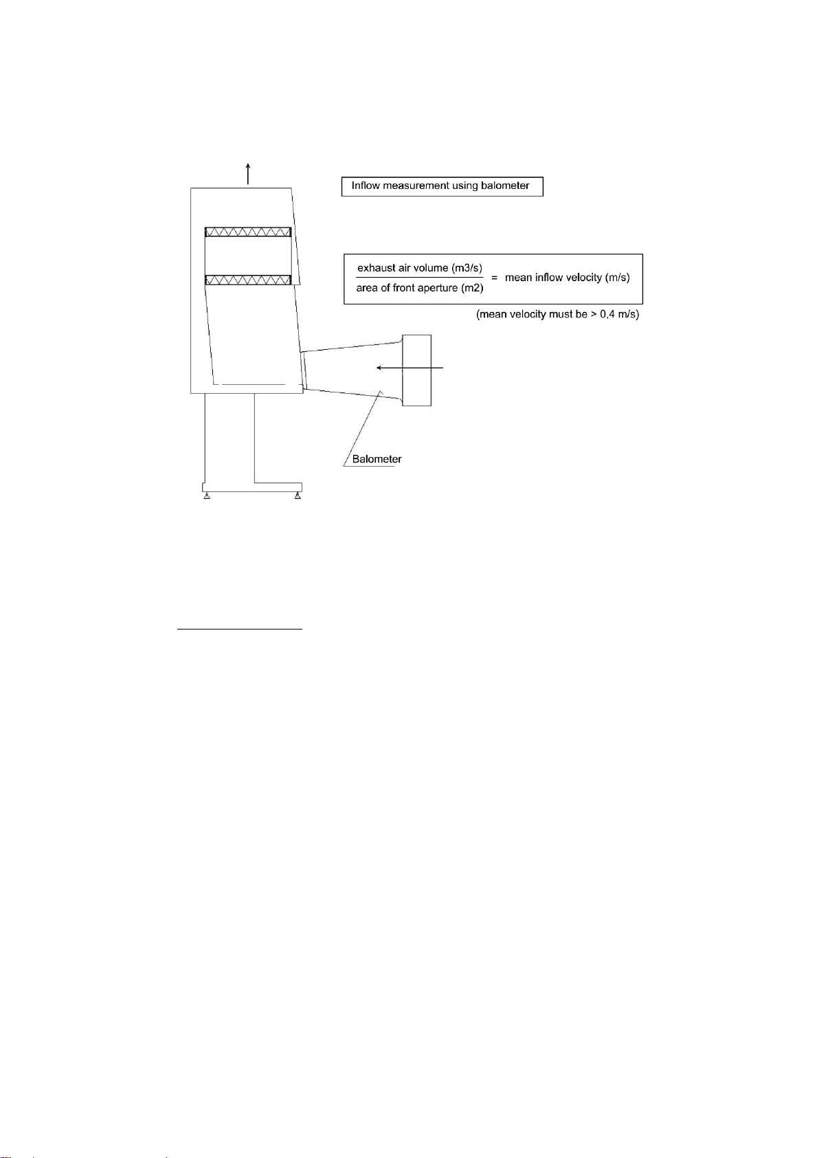
1.1.2 Inflow (using balometer).................................................................................................................7
1.1.3 Airflow visualization (smoke test) ...................................................................................................9
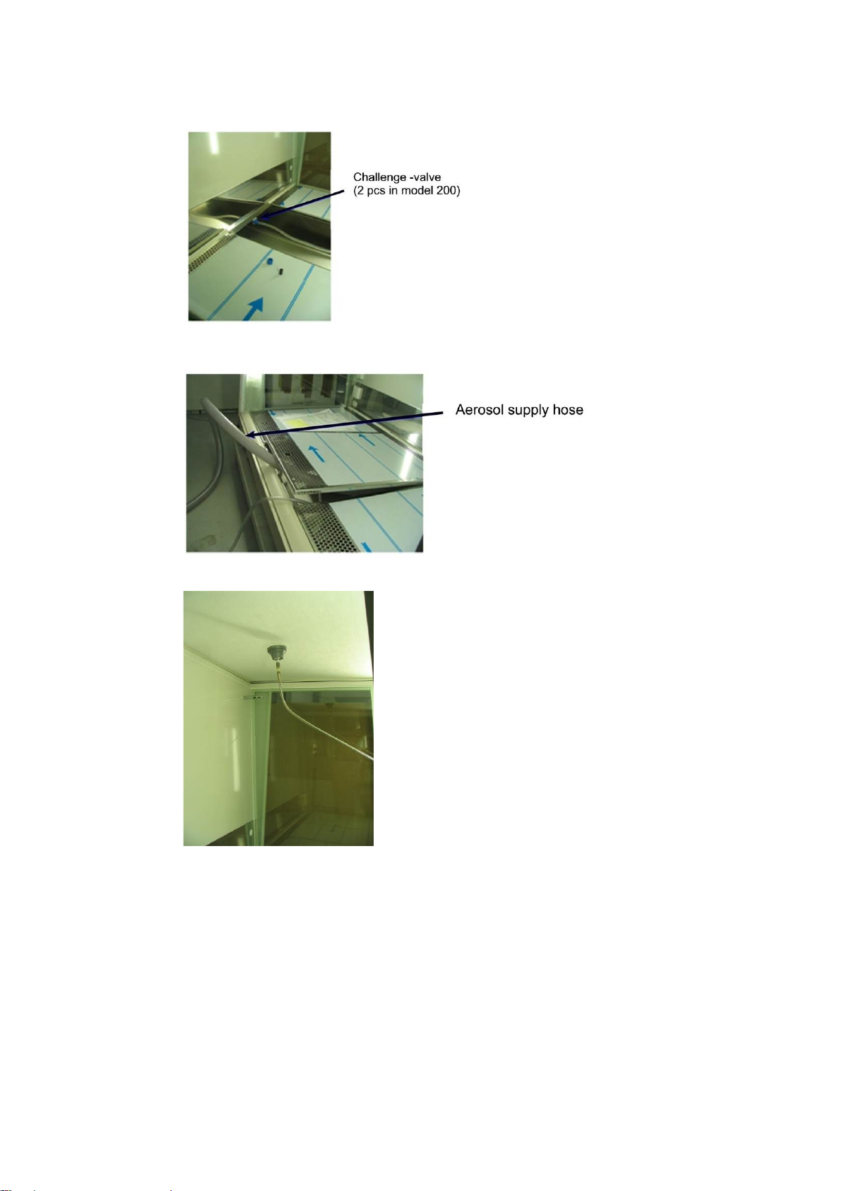
1.2 Aerosol challenge test of filters............................................................................................9
1.2.1 In general........................................................................................................................................9
1.2.2 SF, MF and CW-V cabinets:...........................................................................................................9
1.2.3 Exhaust filters...............................................................................................................................11
1.2.4 XL cabinets...................................................................................................................................12
1.2.5 DEF cabinets................................................................................................................................14
1.2.6 CW-V cabinets..............................................................................................................................17
1.2.7 Acceptance criterions:..................................................................................................................17
1.3 KI -Diskus test...................................................................................................................18
2MAINTENANCE.......................................................................................................... 19
2.1 Yearly Maintanance ..........................................................................................................20
2.2 H2O2Decontamination ......................................................................................................21
2.3 Replacing lights.................................................................................................................22
2.4 Changing filters.................................................................................................................23
2.4.1 In general......................................................................................................................................24
2.4.2 SF Cabinets..................................................................................................................................28
2.4.3 MF Cabinets .................................................................................................................................28
2.4.4 DEF Cabinet.................................................................................................................................30
2.4.5 XL cabinets...................................................................................................................................32
2.4.6 CW-V cabinets..............................................................................................................................35
2.4.7 After filter change .........................................................................................................................36
2.5 Changing main board........................................................................................................36
3MATERIALS ............................................................................................................... 37
4DISCHARGING THE CABINET.................................................................................. 37
5SOFTWARE UPDATE................................................................................................ 38
5.1 Update Core version.........................................................................................................38
5.2 Update Biocontro i.............................................................................................................38
5.3 Update Main version.........................................................................................................40
6TECHNICAL DATA..................................................................................................... 41
7SPARE PARTS LIST.................................................................................................. 46
8CIRCUIT DIAGRAMS ................................................................................................. 56
9SERVICE HISTORY.................................................................................................... 64
10 TROUBLE SHOOTING .............................................................................................. 65

4
1 TESTING
TÜV Group performs all the Biowizard Platinum safety cabinets feature classification and verifications as
well as all typetestings (excluding Biowizard Platinum DEF and CW-V models).
All cabinets are adjusted and tested at the factory. Factory settings are giving the best protection for the
products handled on work surface against the contamination and protects the user of health hazardous
substances. Factory test reports are documentied in separate measurement report.
Before first start up of the cabinet (new installation) or if cabinet surroundings has been changed
(e.g changing cabinet location) following installation tests must be performed:
Retention at front aperture:
•Check that manufacturer’s specifications is met
•Airflow rate measurements (inflow and downflow measurement in work chamber)
•Movement of airflow in work chamber (smoke test )
•When needed Kl-Discus test can be done to protect the user at the site. (evaluation of protection
factor)
Filters:
•Filter’s leaktightness test
Product protection:
•Check that manufacturer’s specifications is met
•Airflow rate measurements (inflow and downflow measurement in work chamber)
•Movement of airflow in work chamber (smoke test )
•When needed Kl-Discus test can be done to protect the user at the site. (evaluation of protection
factor)
Cross contamination
•Check that manufacturer’s specifications is met
NOTE! According to the standard EN 12469 all the below mentioned installation
tests must be performed after the cabinet has been installed or every time after
installing or surroundings has been changed before turning it on first time. For
the detailed information from testing, please contact your local Kojair Tech Oy
representative. See www.kojair.com
!
NOTE! Testing should only be performed by service personnel authorized by the
Kojair Tech Oy.
!
NOTE! Cleanwizard Platinum cabinet is not EN 12469 Class II safety cabinet.
!

5
1.1 Airflow measurements
Airflow rates are measured either with calibrated anemometer, usually measured in several points or with
calibrated measuring device, which can be used for measuring the airflows in ventilation duct. (see
measurement report the devices used in testing)
1.1.1 Downflow (hotwire anemometer)
Switch on the cabinet. Take hot wire anometer into working chamber. Measuring point should be in
horizontal plane, 50mm to 100mm above the top edge of working aperture. Make measurements over a
period of at least 1 min in each, at least in 8 positions. Measuring positions are locatingin “lines”. Cabinet’s
depth paraller (2 pcs) specified as per following: the rear line locates ¼ of the depth of the working space
forward of the rear wall and the front along the same distance behind the front window. Cabinet’s width
paraller lines (4 pcs) are locating as per following: outermost lineslocates at 1/8 of the width of thecabinet
towards to the middle. The rest of the lines (2 pcs) are divided to ¼ gaps (see picture 1.).
Procedure:
Downflow is measured with hotwire anemometer using following settings:
Hot wire anometer is placed on measuring point. Every measurement takes at least 1 minute. Mean value
is calculated from the measurements. Measurement results and mean value are noted on measurement
report.
Measuring plane = 100mm above the top edge of working aperture
Type
Width
Measuring points
Platinum SF, MF, DEF, CW-V 100 1094mm 8
Platinum SF, MF, DEF, XL, CW-V 130 1399mm 8
Platinum SF, MF, DEF, XL, CW-V 170 1744mm 8
Platinum SF, MF, DEF, XL, CW-V 200 2049mm 8

6
Picture 1. Measurement points in Biowizard Platinum cabinets
Accteptance criterions:
To achieve product protection, mean downflow velocity must be between 0,25 m/s – 0,50 m/s, and no
individual measurement should differ from the mean value more than ±20 %
Alarm: if the air velocity should exceed the present alarm, an acoustic and visual alarm will be activated,
which can not be muted.

7
1.1.2 Inflow (using balometer)
Switch on the cabinet. Measure the inflow airflow velocity (l/s) with balometer. Convert table from l/s to
m3/h can be seen below.
Procedure:
Biowizard Platinum cabinet’s inflow air velocity and exhaust air volume is measured with a balometer
using following settings:
Height of the front aperture= 0,2m (normal working height in all models)
Width of the front aperture: Platinum SF, MF, DEF 100 0,907m
Platinum SF, MF, DEF, XL 130 1,212 m
Platinum SF, MF, DEF, XL 170 1,557 m
Platinum SF, MF, DEF, XL 200 1,862 m
Area of the front aperture: Platinum SF, MF, DEF 100 0,181 m2
Platinum SF, MF, DEF, XL 130 0,242 m2
Platinum SF, MF, DEF, XL 170 0,311 m2
Platinum SF, MF, DEF, XL 200 0,373 m2
Minimum inflow air velocity in front aperture = 0,40m/s
(Acoustic and visual alarm is given if inflow velocity is under 0,40 m/s)
Inflow air velocity in front aperture = 0,45m/s (Kojair Tech Oy set point)
Maximum inflow air velocity in front aperture = 0.60m/s
(acoustic and visual alarm given if inflow velocity is more than 0,60 m/s)
Measurer reads from the balometer cabinets exhaust air volume (l/s). Measurer checks that exhaust air
volume is between min. and max exhaust air volume, this way he can be sure that the mean air velocity
in let is ≥0.40 m/s. Min and max.exhaust air volumes and Kojair set point air volumes are listed in table
below.
Cabinets model
Min. inflow air volume
(when inflow velocity is
0,40 m/s)
Inflow air volume
(when inflow velocity is
0,45 m/s)
Max. inflow air volume
(when inflow velocity
0,60 m/s)
(l/s) (m3/h) (l/s) (m3/h) (l/s) (m3/h)
Platinum SF, MF, DEF 100 75 270 82 295 109 392
Platinum SF, MF, DEF, XL 130 97 349 109 392 145 522
Platinum SF, MF, DEF, XL 170 125 450 140 504 187 673
Platinum SF, MF, DEF, XL 200 149 536 168 604 224 806
NOTE! A method for measuring columetric airflow rate in circular exhaust ducts is
given in standard BS 848–1:1997.
!

8
Picture 2. Inflow measurement using balometer.
Accteptance criterions:
The inflow air velocity in the front aperture must be ≥0,40 m/s.

9
1.1.3 Airflow visualization (smoke test)
Purpose of this test is to verify that no recirculated air escapes out of the working space to surrounding
room, and that the replacement air moves through the front grid to the bottom basin of the cabinet without
visible turbulences (see picture 3). Both smoke sticks and smoke generator can be used as a smoke
source.
Picture 3. Airflow in work space (visualization)
1.2 Aerosol challenge test of filters
1.2.1 In general
Operate the cabinet and induce the aerosol challenge at a suitable location on the upstream side of HEPA
filters, seals and construction joints to be tested. Ensure that the challenge aerosol concentration is
uniform on the upstream HEPA filter face. Measure average upstream aerosol concentration.
Scan the downstream side of the HEPA filter by passing the aerosol detection probe slightly overlapping
over the entore surface of the HEPA filter.Scan the entire periphery of the filter, the junction between the
filter, and the filter mounting frame. Determine traverse scan rate, sample acquisition time and the actual
particle counts characterizes a leak.
1.2.2 SF, MF and CW-V cabinets:
Down flow filter:
Switch on the aerosol photometer and its pump. Connect the 100% PAO sample pipe to the challenge-
valve. Induce aerosol to the plenum; take the aerosol supply hose under the table top, close to the back
channel (see picture 4) and turn on the aerosol-generator. Calibrate the aerosol photometer after you
have supplied aerosol to the cabinet 1-2 minutes. Scan the downstream side of the filter over the entire
surface. Scan also all filters joints and sealant for leaks (seepicture 6). See below acceptance criteria and
also measurement report, leakage test (DEHS) by EN-12469-00/BS 5726-92.

10
Picture 4. Position of the challenge-valve in the cabinet
Picture 5. Aerosol supply hose.
Picture 6. Scanning the downstream side of the main filler surface.

11
1.2.3 Exhaust filters
Open the fastening screws of the exhaust air adjusting plates and remove the plate. Then remove the
exhaust air grid.
Picture 7. Removing exhaust air adjusting plates.
Picture 8. Exhaust air grid.

12
Scan the filter joints and filter mediaarea. Specialscanning probescan be orderedfrom us. Please contact
your local dealer.
Picture 9. Scanning the exhaust filter joints and filter media.
1.2.4 XL cabinets
Down flow filter: Turn on the aerosol photometer and its pump. Connect the 100% PAO sample pipe to
the challenge -valve. Induce aerosol to the plenum; take the aerosol supply hose under the table top,
close to the back channel through scanning hole (see picture 13) and turn on the aerosol -generator.
Calibrate the aerosol photometer after you have supplied aerosol to the cabinet 1-2 minutes. Scan the
downstream side of the filter over the entire surface. Scan also all filter joints and sealant for leaks (see
picture 12). See below acceptance criteria and also measurement report, leakage test (DEHS) by EN-
12469-00/BS 5726-92.

13
Picture 10. Position of the challenge –valve and aerosol supply hose.
Picture 11. Scanning the downstream side of the main filter surface.
Pre filters: Turn on the aerosol photometer and its pump. Take the 100% PAO sample pipe to the bottom
of the pre filter cover (see picture 12). Induce aerosol to the back side of the pre filter; take the aerosol
supply hose under the table top, to the bottom of the pre filter cover and turn on the aerosol -generator.
Calibrate the aerosol photometer after you have supplied aerosol to the cabinet 1-2 minutes. Scan the
opposite side of the filter over the entire surface with the scanning pipe. Scan also all filter joints and
sealant for leaks (see picture 11). See below acceptance criteria and also measurement report, leakage
test (DEHS) by EN-12469-00/BS 5726-92.
Picture 12. Position of the challenge –valve, aerosol supply hose and 100% PAO sample pipe.
Exhaust filters:
NOTE! Be extremely careful not to break filter surfaces when scanning trought
middle pressure chamber.
!

14
Scan holes are located behind the service hatches (see picture 13.).
Picture 13. Service hatches.
When scanning the exhaust filter open the screws of the service hatch and cut silicon seams. Now you
can do leakage test with particle counter or aerosol photometer through these scan holes.
1.2.5 DEF cabinets
Down filters: Down flow filter scanning procedure is identical to down flow filter scanning procedure of
SF and MF cabinets. See chapter down flow leakage scanning of SF and MF cabinets.
Exhaust filters :
Scan and DHS supply holes are located behind the service hatches (see picture 14.).
NOTE! Be extremely careful not to break filter surfaces when scanning trought
middle pressure chamber.
!
Service hatch and the scan holes

15
Picture 14. Service hatches.
When scanning the lower exhaust filter open the screws of the service hatch and cut silicon seams. In
Platinum 200 DEF there are two service hatches. Now you can do leakage test with particle counter
or aerosol photometer through these scan holes.
Scanning of upper exhaust filter is carried out from the top of the cabinet.
Remove the fixing screws of the protective grid and remove the grid.
Picture 15. Protective grid
Remove the fixing screws of the fan plate and loosen the electrical quick connectors of the fan.
NOTE! Disconnected cabinet from electricity when removing the protective grid of
the exhaust fan and the fan itself.
!
Protective grid
Fixing screws of the fan plate

16
Picture 16. Fixing screws of the fan plate.
Remove the fan and the fan plate.
Picture 17. Removing the fan and the fan plate.
Supply DOP/DHS smoke through the scan holes, which are behind the service hatch and same time
scan above the upper exhaust filter.
Fan and the fan plate

17
1.2.6 CW-V cabinets
Down filters: Down flow filter scanning procedure is identical to exhaust filter scanning procedure of SF
and MF cabinets. See chapter exhaust filter leakage scanning of SF and MF cabinets.
1.2.7 Acceptance criterions:
If a discrete particle counter is used, the local penetration of a HEPA filter with 0.005 % integral,
penetration should not be more than 0.05 %.
If an aerosol photometer is used, the local penetration of a HEPA filter should not be more than 0.01 %

18
1.3 KI -Diskus test
Testing the air curtain performance in the front opening is a way to confirm the reliability of the safety
settings. With special KI discus test equipment you can challenge the air curtain with particles and check
the actual retention. For microbiological safety cabinets this testing procedure is optional. For Cytotoxic
safety cabinets this test is obligatory and the test should be performed according the DIN 12980, to be
sure of the operator protection. The test should be repeated after defined period, recommendation is 2
years, or if surrounding conditions changes.
The necesseray testing equipment and acceptance criteria (Protection factor Apf ≥ 1x10⁵) are described
in the currect EN-Standard 12469. The test should only be performed by well trained personnel.
Kojair Tech Oy service organization or our higly qualified dealers are offering wide range of testin,
maintenance and validation services. To find out more, please contact your local Kojair Tech Oy
representative. www.kojair.com

19
2 MAINTENANCE
Standard EN 12469:2000, Annex K (informative) K.1 General:
Routine maintenance tests should be carried out on class1, class 2 and class 3 cabinets at reqular
intervals or as determined by regulatory authorities.
All equipment used of these tests should be regularly calibrated and the certificates should be available.
In additional, the latest maintenance date should be in an easily visible position.
Antiflowback-valve functional check must be performed (if in use) to ensure it is functioning and is clearly
visible.
Standard EN 12469:2000, Annex K (informative) K.3 Class 2 cabinets:
All internal and external surface of the safety cabinet shouldbe visually examined to ensure that there are
no surface defects, cracks or other damage.
If cabinet has extraction duct system, it should be visually inspected to ensure that it is free from defects,
cracks or other damage, and it’s clearly labeled.
The alarm indicators should be checked according the manufacture’s specification. Should the alarm
device require calibration, the manufacturer should indicate the recalibration time intervals in order the
alarms to trip according to the set limits.
The down flow air velocity in the working area of the cabinet should be measured in accordance with the
method given in annex G, according to manufacturer’s instructions and to table H.1.
If prefilter is fitted, it should be changed before airflow measurements are done.
In cabinets with two exhaust filters, both filters should be tested separately.
NOTE! Yearly maintenance:
Test your cabinet at least once a year to ensure the best protection for the user,
products and environment. Ask for more detailed information from your nearest
Kojair dealer or visit manufactures’s wed site: www.kojair.com
!
NOTE! Only person who is trained / authorized by Kojair Tech OY is allowed to
maintain the cabinet.
!
NOTE! To ensure the validity of guarantee and EC-declaration of conformity, use
only original spare parts (listed on the spare parts list)
!
NOTE! In general daily maintenace for the cabinet requires only cleaning.
Technicians trained by Kojair Tech Oy will determine the need of other
maintenance, including filter change in yearly inspections.
!

20
Check laboratory conditions before maintanance work :
1. Always check what kind of substances have been handled in the cabinet before
maintanance work. Decontamination might be necessary before maintenance work,
depending on which subtances have been used in the cabinet. A responsible technican
or health and safety officer must always be present when changing filters, if for example
cytotoxics or other health hazardous substances have been handled in the cabinet. If
necessary, protective clothing should be worn according to the health and safety
guidelines.
2. Check that enviromental conditions of laboratory room corresponds the values given
in separate installation instaructions.
2.1 Yearly Maintanance
1. Inspect the exterior of the cabinet
a.) check the fixing of the screen. If necessary repair the fixing.
b.) check, that the cabinet’s exhaust air outlet on the top of the cabinet is not blocked,
and cabinet’s exhaust air can freely discharge.
c.) Check the cabinet’s paint condition and make sure that the glasses of the cabinet
are intact. Deep scratches in paint can cause corrosion in a longer period of time.
d.) Check that the cabinet is standing firmly on the base stand. Adjust the screws if
necessary.
2. Check the fixing of the front glas and the condition of the lifting belts
a.) Move cabinet’s front window to its lowest position. Open the front panel. Check
that the adhesive surface is contiguous between the glass and the glass plate. Check
mounting studs. Check that there are not any cracks in the glass around the glass
plate. Lift up the front window manually from its lifting belts. Check that the adhevise
surface is solid.
b.) Check that lifting belts are not worn. Slight traces are normal. Fraying marks are
sign of the need to exchange.
3. Inspect the interior of the cabinet.
a.) Check the condition of all silicon seams inside of the cabinet. When needed,
repair the silicon seams. From a cleanibility and safety perspective, it is important
that the seams are intact.
b.) Check the condition of the table top(s). Deep scratches makes cleaning difficult.
c.) Check gas springs and their fastening
4. Check the functions of the cabinet
a.) Check that the lifting belts forfront windoware tight when it is in its lowest position.
When needed, adjust the belt tightness from the lifting motor.Adjustment screws are
on the right end of the lifting motor.
b.) Check the front window movements and its position sensors. Check that front
window can move freely up and down, and lifting motor does not make abnormal
noise. Check the function of the front window sensors. Move the front window to its
lowest position and check that cabinet switched to half speed mode.
c.) Cabinets with electrical base stand, check that the base stand can freely move up
and down and motor does not make abnormal noise.
d.) Check the functionality of the lights, outlets and magnet valve
.
This manual suits for next models
5
Table of contents
Other Kojair Laboratory Equipment manuals