Ensure that the battery is fully charged before checking problems in the following chart.
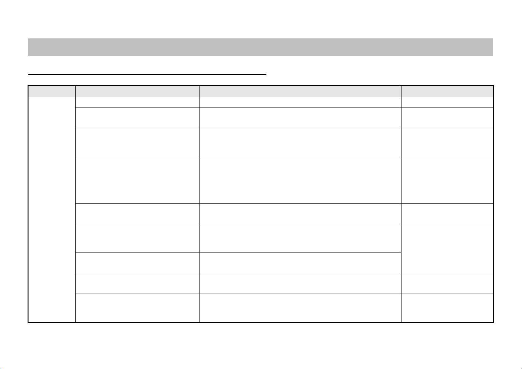
Problem Cause Check Recovery
(1) Motor does
not rotate.
• Wires are not conducting electricity. • Check status of all wires. • Repair any defects.
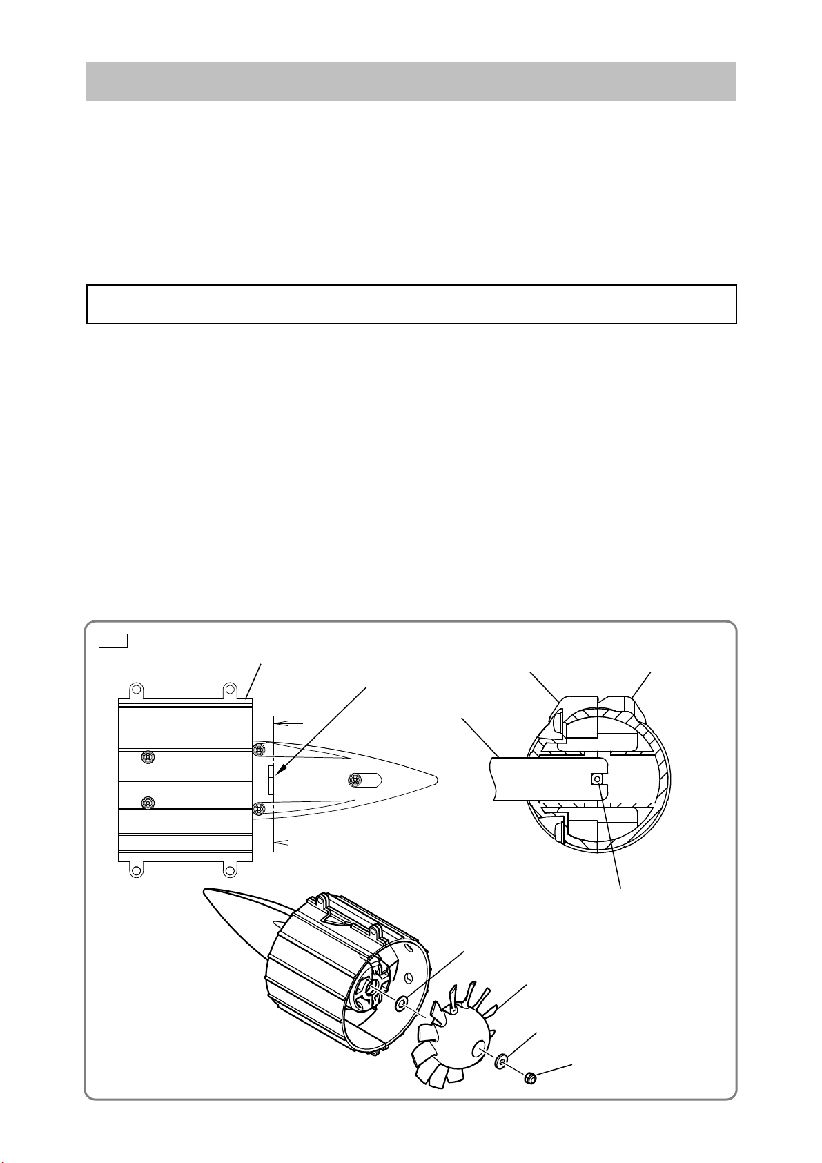
• Foreign matter is caught between the
rotor ass’y and the stator FET PCB.
• Check and ensure that there is no foreign matter between the rotor
ass’y and the stator FET PCB.
• Remove any foreign matter.
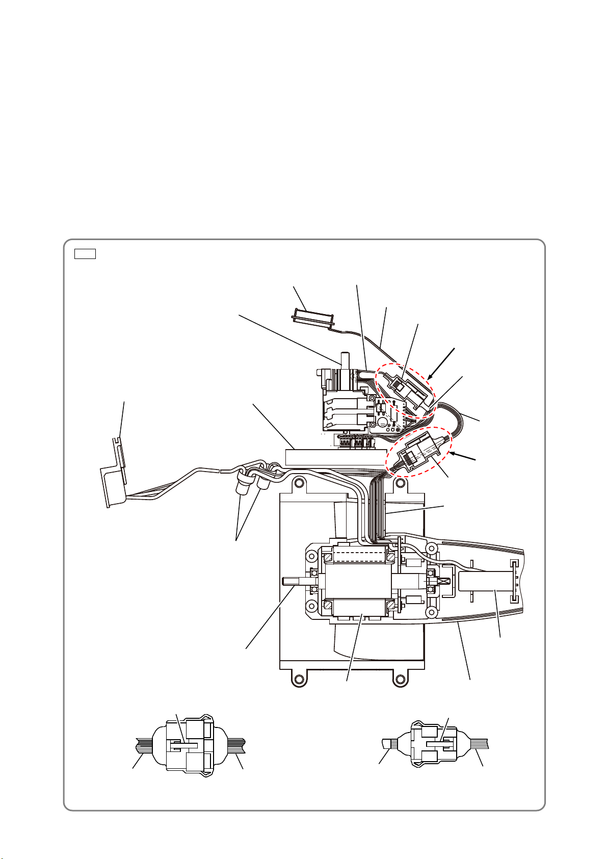
• Faulty connection between the connector
cable (switch) and the connector cable
(CN3).
• Check that the connector is correctly plugged in.
• Check that there is no foreign matter inside the connector. (Refer to
“How to check and replace the power supply unit” on page 9.)
• Reconnect the connector.
• Remove any foreign matter.
• The switch circuit board is malfunctioning
due to presence of dust or water.
• Faulty connection with the switch circuit
board’s internal wire.
• Inspect the switch circuit board for any signs of swelling, scorching,
dust, or water.
• Inspect the internal wire of the switch circuit board for any damage
and ensure that the connection to the circuit board is not
disconnected.
• Replace the wiring ass’y.
• The controller ass’y is malfunctioning due
to presence of dust or water.
• Check status of the circuit board surface for any signs of swelling,
scorching, dust, or water.
• Replace the wiring ass’y.
• The stator FET PCB is malfunctioning
due to presence of dust, water, or
damage caused by impact.
• Check status of the circuit board surface for any signs of swelling,
scorching, dust, water, or damaged FET.
• Replace the wiring ass’y.
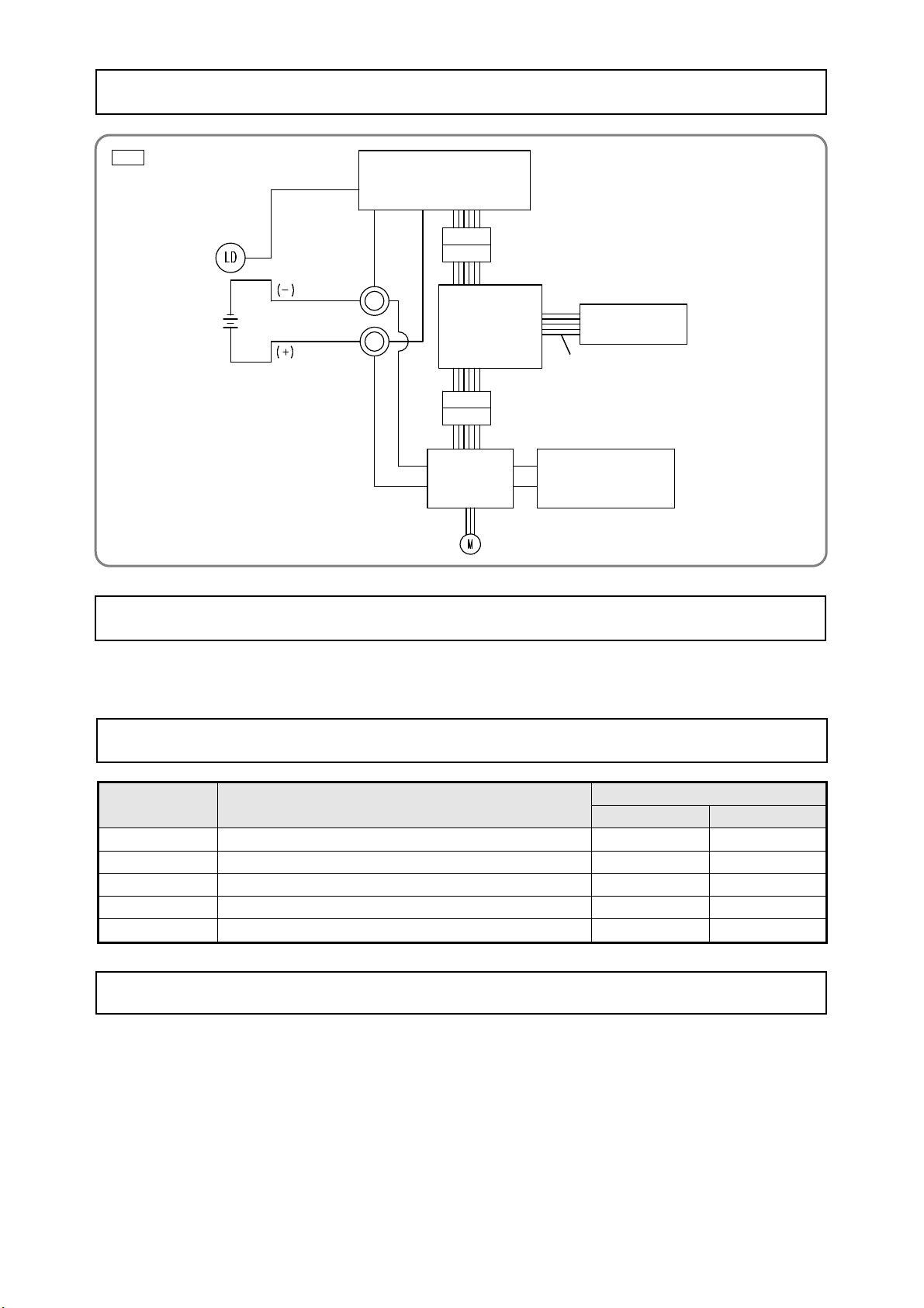
• The FET of the stator FET PCB is
malfunctioning.
• Check according to “How to check and replace the power supply unit”
on page 9.
• The rotor is not correctly attached to the
magnet.
• Check that the rotor is correctly attached to the magnet. • Replace the rotor ass’y.
• Faulty connection between the connector
cable (FET) and the connector cable
(controller).
• Check that the connector is correctly plugged in.
• Check that there is no foreign matter inside the connector. (Refer to
“How to check and replace the power supply unit” on page 9.)
• Reconnect the connector.
• Remove any foreign matter.
-1-
TROUBLESHOOTING GUIDE