KOKUA LIKEtoBIKE 20 User manual

ASSEMBLY AND OPERATING INSTRUCTIONS
LIKEtoBIKE 20
Please read this manual carefully before using the LIKEtoBIKE for the rst time!
The assembly must be done by an adult!
1. Remove all packaging materials. Contents of the enclosed acces-
sory box are: Pedals, hexagon tool (Allen key) (4mm,5mm,6mm),
Front and Rear Reectors, Touch-up paint, Instructions.
2. After loosening the seat post clamp screw, slide the seat post
into the seat tube.
Important: Please note the minimum insertion depth of
the seat post! This is indicated by a line marked on the
seat post! The seat post must not be pulled out beyond
this mark, otherwise a secure connection to the down
tube is not guaranteed! The saddle can be adjusted in the lon-
gitudinal direction and inclination after loosening the saddle
fastening screw. Then tighten this screw again!
Adjusting the correct saddle height: Place a pedal in the lowest
position. If the child is sitting on the saddle, the child must be able
to touch this pedal with his heel (outstretched leg). Make sure that
the childs hips stay level and do not tip over to the side!
Seat post
clamping screw
Right Pedal
Left Pedal
4. Now mount the pedals. Turn the pedal axles by hand until snug!
Then tighten with a 15 mm wrench.
Important: The right pedal is mounted clockwise, the
left pedal counterclockwise! The pedals are marked on
the pedal axle with an „R“ for the right pedal and an „L“
for the left. It is important to remember this if you need to
loosen the pedal axle someday. So that the pedals can easily be
loosened again later, grease them lightly before mounting.
After the rst long ride please check that the pedals are
seated rmly! Loose pedals could damage the thread of the
cranks or cause a fall!
3. 3. Insert the stem with the already mounted handlebar onto the
steering tube.
Now align the handlebar in the direction of travel at the desired
height and tighten the height adjustment screw with a 5 mm Allen
key (torque 10 Nm).
Under no circumstances may the stem be mounted over the
upper edge of the steering tube!
After loosening the angle adjustment screw, you can ne
tune the handlebar position by changing the stem angle. Then re-
tighten the angle adjustment screw (torque 10 Nm).
Use the headset adjustment screw to adjust the headset.
Very important: With this screw you adjust only the
headset clearance! This screw is not used to attach the
stem!
Adjustment for
headset clearance
(NOT TO FIX THE
STEM!)
Angle adjustment
screw
Steering tube
Height
adjustment screw
Saddle fastening
screw

7. 7. The distance between the brake pads and the rim can be
changed by slightly loosening the brake cable clamp screw and
slightly reducing or increasing the tension of the cable.
Then tighten the brake cable clamp screw again! Wear
of the brake pads may necessitate a readjustment of
the brake. Small adjustments can be done by using the
brake adjustment screw on the brake lever.
6. The brake lever/handlebar distance can be adjusted to the
child‘s reach with the brake lever adjustment screw. Afterwards
the correct distance of the brake pad to the rim may have to
be reset! They should be as close as possible to the rim, but
not touch until the lever is pulled.
The left brake handle is assigned to the front brake, the right to the
rear brake!
Center the rim and close the quick release lever so that it is parallel
to the left fork.
Important: The quick-release lever must be very dif-
cult to swing into the closed position! Press the quick
release lever into position with the ball of your thumb
while you wrap your ngers around the back of the fork!
If the quick release lever can be turned in the closed position,
the clamping force is not sufcient. The bike could come loo-
se during the ride! Open the quick-release lever again and pull
the clamping nut a little tighter. Then close the quick release
lever as described above! Do not forget to reinsert the brake
cable guide tube and check the brakes!
5. To install the front wheel, the front brake must be released. By
squeezing the two brake arms and pulling gently on the brake
cable guide tube, the brake cable can be unhooked.
Now insert the wheel into the fork so that the axle ends to the right
and left of the hub body are correctly seated in the ends. Remove
the tension nut and a spring from the quick release axle. Now
insert the quick-release axle from the left side through the hollow
axle of the wheel hub.
Then push the second spring onto the quick-release axle.
Pull the quick release clamp open.
Tighten the quick release nut until it touches the dropout.
Brake cable
guide tubes
Brake Arm
Brake lever
adjustment screw
Brake
adjustment screw
Brake cable
clamp screw

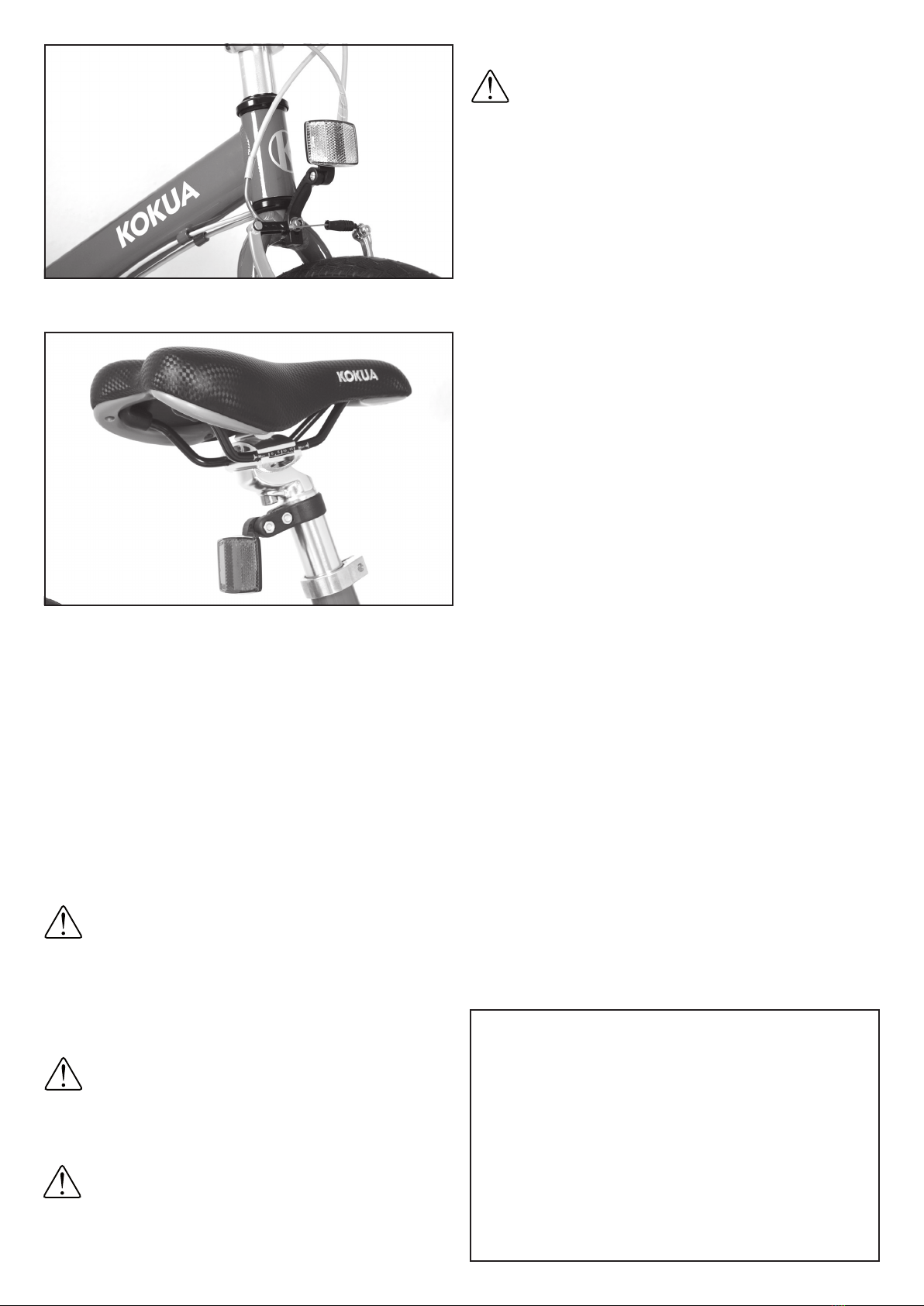
9. The rear reector is attached to the seat post.
8. The front white reector is attached to the front fork.
Tighten the self-locking nut well!
KOKUA Bikes GmbH
Schwerzfelder Str. 3
D-52159 Roetgen
Tel.: +49 2471 134 160
Fax: +49 2471 134 161
Email: [email protected]
Attention!
Important safety
instructions!
The LIKEtoBIKE is not a means of transport and may not be used
on public roads! Only allow your child to ride in protected areas
(such as a pedestrian zone, playground, sidewalk, etc.). When
riding on public roads, please observe the legal requirements,
such as: Lighting and reectors.
Explain to your child how to handle the LIKEtoBIKE correctly,
point out possible dangers!
Explain to the child how to use the brakes!
The child may only ride under adult supervision!
The child has to wear sturdy shoes and a bicycle helmet! It is also
useful to wear cycling gloves.
No riding on sloping terrain, stairs, etc.!
Regularly check the tightness of the wheel nuts!
Regularly check the functionality of the brakes!
Regularly check the tire pressure!
If a defect is detected on the LIKEtoBIKE, do not let the child ride!
WARNING
As is the case with all mechanical components, the bicycle is expo-
sed to wear and high stresses. Different materials and components
can react differently in terms of wear or fatigue due to the stresses.
If the design life of a component is exceeded, the component may
suddenly fail and possibly cause injury to the rider. Any type of
cracking, scratching or color change in highly stressed areas is an
indication that the life of the component has been reached and that
the part should be replaced.
The LIKEtoBIKE was manufactured according to EN 14764 (city
and trekking bicycles) and designed for a permissible total weight
of 100 kg.
Maintenance and
inspection instructions
All painted surfaces should be cleaned regularly with mild deter-
gent, warm water and a soft sponge to remove mud and dirt. From
time to time it is recommended to preserve the paintwork and all
metal surfaces, screws and nuts with a hard wax.
The rims must not be waxed, as this would affect the bra-
king performance!
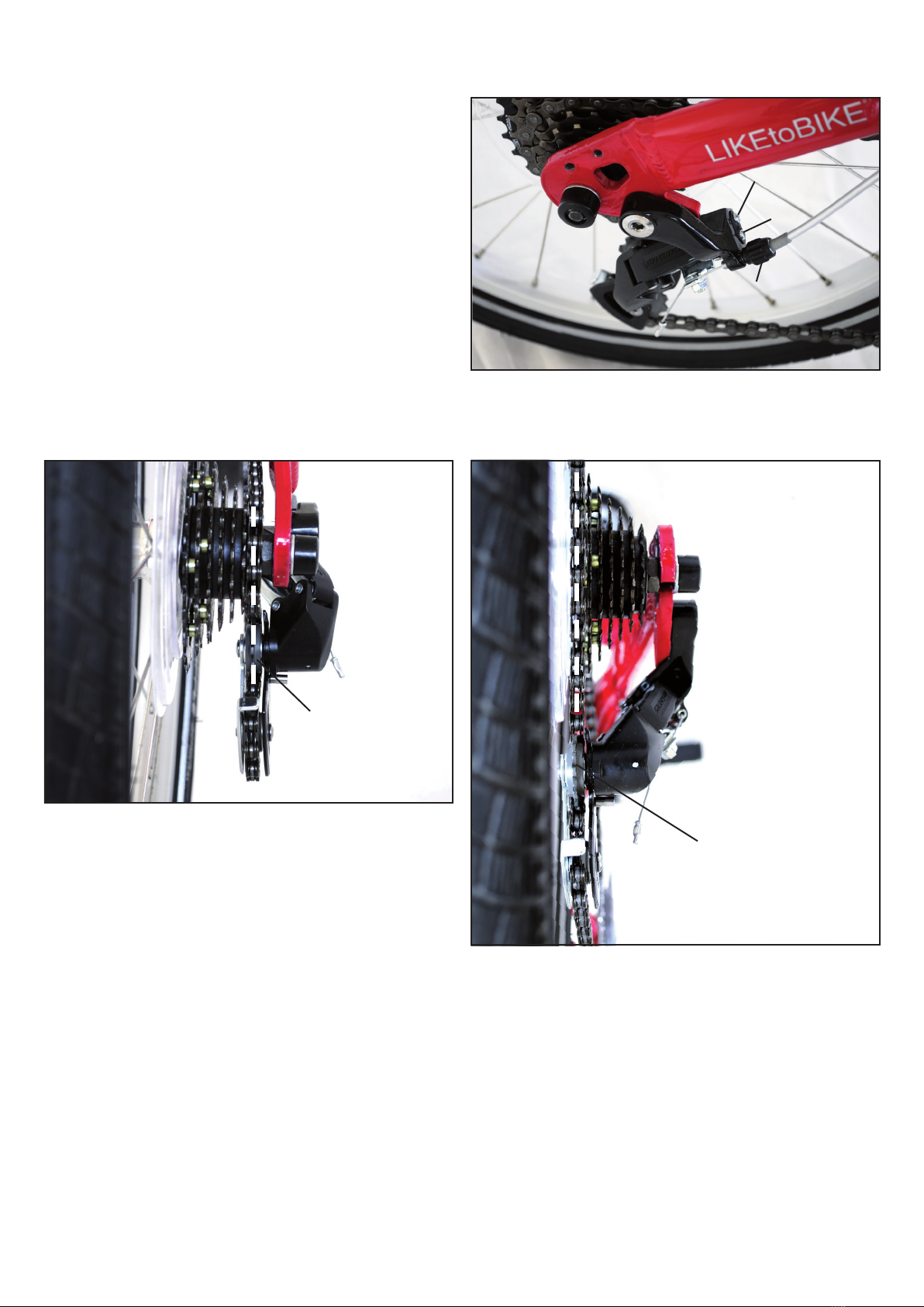
The chain and rear derailleur should also be cleaned regu-
larly. Then treat the chain and all moving parts of the derailleur with
oil or a special lubricant.
Please regularly check the frame and fork for possible damage.
The brake and external trains should also be bent or otherwise
damaged.
be examined.
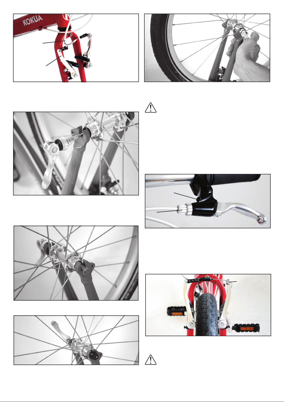
The brake pads should be checked before each ride, in
case of heavy wear they must be replaced by a trained
bike mechanic! The rim is also part of the braking system
and must be checked regularly for damage and wear!
We recommend that the LIKEtoBIKE be inspected annually by a
professional bike mechanic.
Attention!
Important safety instructions!

The Neos rear derailleur is an extremely compact derailleur with
very minimal reach. The ground clearance is much larger than in a
conventional circuit. This signicantly reduces the risk of damage!
It was specially developed for small wheels.
This is an inverse rear derailleur - when pulling on the shift cable,
the chain is moved to the smaller sprocket, unlike the normal rear
derailleur. This makes it easier for your child to shift into the easier
gears on hills, while jumping the chain on the larger sprockets is
supported by the spring mechanism of the derailleur!
High set screw
low set screw
Shift cable adjusting
screw
upper guide roller
upper guide roller
Chain on the smallest pinion (7th gear)
Chain on the largest sprocket (1st gear)
2. Now switch to 1st gear. Now the upper guide pulley of the ge-
arshift should be just under the largest pinion. You can precisely
adjust this position with the „low setting screw“ (for the low gear
ratio) (by turning counterclockwise, the cage moves inwards to-
wards the wheel, turning it clockwise to the outside). This setting
prevents the chain from jumping over the 1st pinion towards the
spoke guard.
3. If the chain produces a rattling noise on the pinions, adjust the
chain with the shift cable adjustment screw. Turning to the right
causes the shift cable to be moved to the left, turning left to shift it
to the right.
An optimal setting is achieved when the adjusting screw is tighte-
ned while the crankset is turned and the chain runs over the se-
cond largest pinion (2nd gear) until a rasping noise occurs. Then
loosen the adjusting screw again by 360 °. Now the chain should
run clean.
Adjustment of the rear derailleur
The rear derailleur can be adjusted via the adjusting screws and
the shift cable adjusting screw:
1. Turn the shift handle to the 7th gear while turning the crank.
With the „high adjustment screw“ (for the high gear ratio), set the
travel limit so that the upper guide pulley of the gear box is just
below the smallest sprocket when you look at the sprocket from
behind (by turning it counterclockwise) outside, by turning clockwi-
se inward towards the wheel)! This setting prevents the chain from
jumping over the 7th pinion.
The Suntour NEOS rear derailleur

Height
adjustment screw
In order for the LIKEtoBIKE to take up less space during transport
(for example in the car trunk), the stem can be turned by 90 ° with
just a few hand movements and swiveled downwards. As a tool,
only a 5 mm Allen key is needed.
1. After loosening the height adjusting screw, lift the stem upwards
from the shaft tube sleeve and put it back on by 90 ° to the left.
Then tighten the height adjustment screw again slightly. (Image 1)
2. Loosen the angle adjustment screw and swing the stem down.
Now retighten the angle adjustment screw. (Picture 2)
Angle
adjustment screw
Steering tube
Bild 1 Bild 2
The adjustable stem
KOKUA Bikes GmbH
Schwerzfelder Str. 3
D-52159 Roetgen
Tel.: +49 2471 134 160
Fax: +49 2471 134 161
Email: [email protected]
Manual LIKEtoBIKE 20, 12-2017
Table of contents
Other KOKUA Bicycle manuals