Kolida SDE-28S User manual

SDE-28S Digital Echo Sounder
User Manual

Contents
Chapter 1 Preview...................................................................................................................................................... 3
1.1, Introduction .................................................................................................................................................. 3
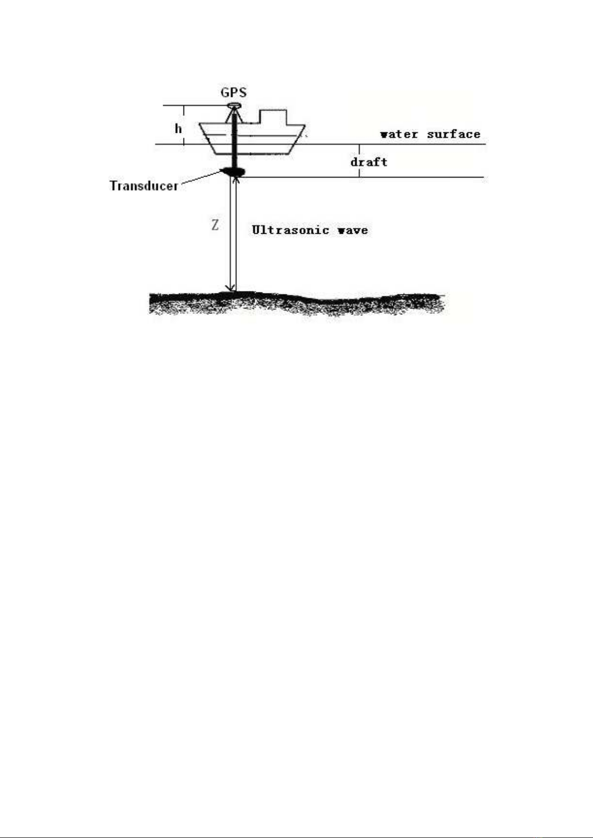
1.2, Echo Sounding Principles.............................................................................................................................. 3
Chapter 2 SDE-28S+ Hardware................................................................................................................................. 5
2.1, Front components......................................................................................................................................... 5
2.2, Side components .......................................................................................................................................... 6
2.3, Accessories ................................................................................................................................................... 7
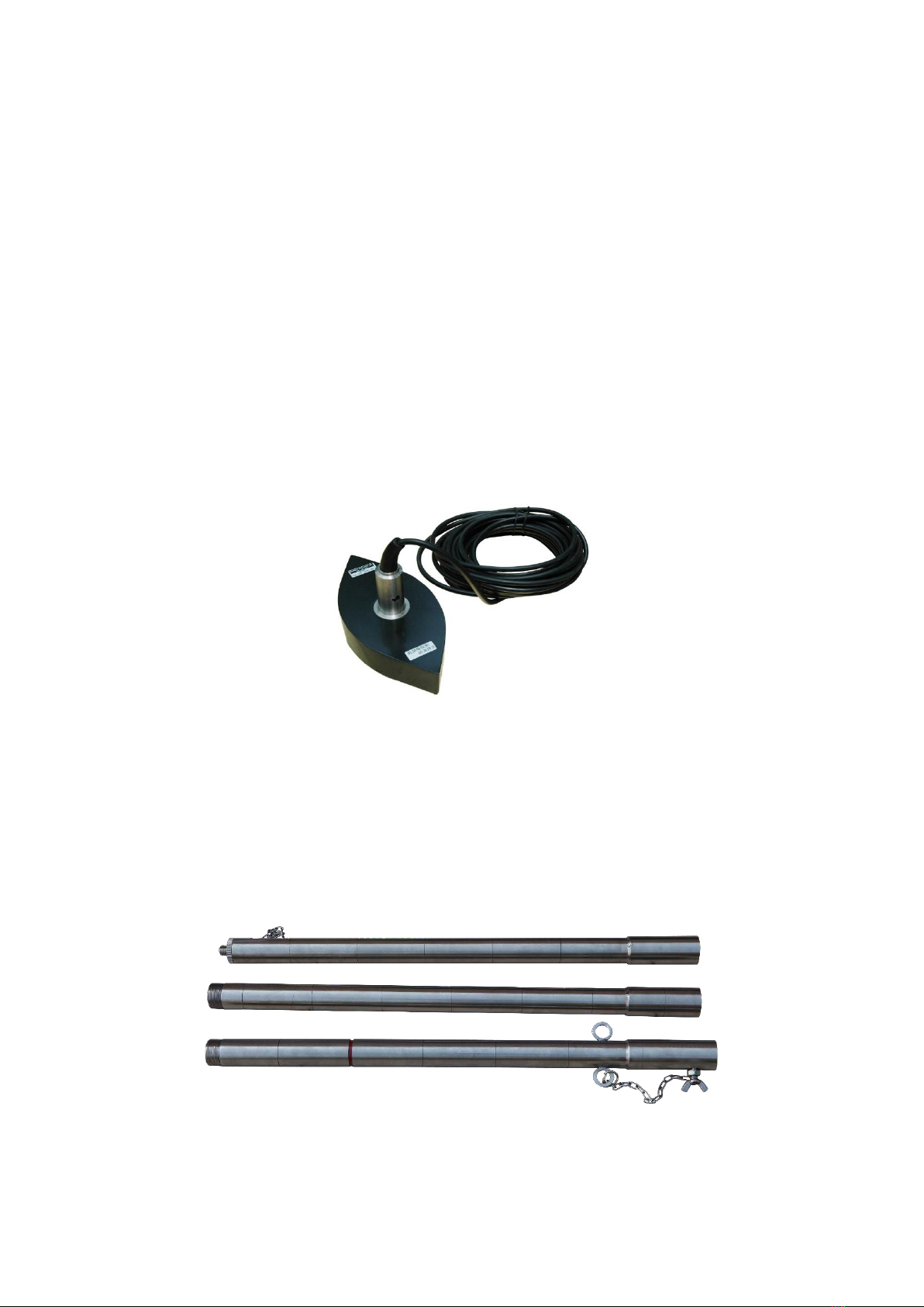
2.3.1, Transducer........................................................................................................................................ 7
2.3.2, Transducer pole................................................................................................................................ 7
2.3.3, Power supply cable/adapter........................................................................................................... 8
2.3.4, I/O devices........................................................................................................................................ 8
2.3.5, Instrument case................................................................................................................................ 9
Chapter 3 Software................................................................................................................................................... 10
3.1, EchoSounder............................................................................................................................................... 10
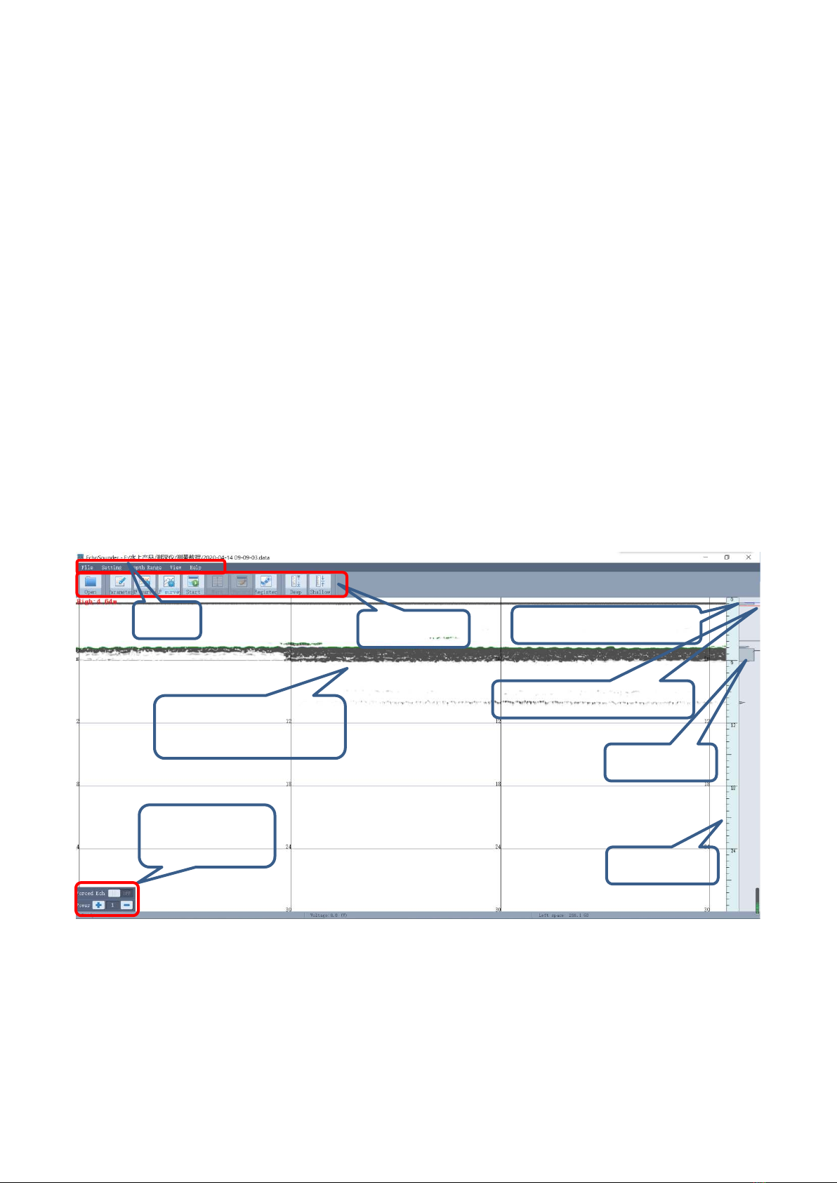
3.1.1, EchoSounder main interface ......................................................................................................... 10
3.1.2, Menu................................................................................................................................................ 12
3.1.3, Toolbar............................................................................................................................................ 23
3.2, HySurvey ..................................................................................................................................................... 25
3.2.1, Main interface................................................................................................................................. 25
3.2.2, Menu................................................................................................................................................ 26
3.2.3, Toolbar............................................................................................................................................ 73
3.2.4, Navigation info/GPS1 plot............................................................................................................. 75
3.2.5, Message window............................................................................................................................ 76
3.2.6, Depth curve window...................................................................................................................... 76
Chapter 4 Hardware installation............................................................................................................................. 77
4.1, Transducer installation................................................................................................................................ 77
4.2, GNSS receiver connection........................................................................................................................... 78
Chapter 5 Specifications .......................................................................................................................................... 79

Chapter 1 Preview
1.1, Introduction
KOLIDA SDE-28S+ echo sounder is a kind of industrial control and digital echo sounder which is
integrated with the 12.1-inch TFT-LCD color screen, industrial control unit, echo sounding unit,
data processor, internal memory unit and kinds of interfaces and I/O devices. The special design
can protect it from dust, water, and strong vibration. It collects depth measurement, graphical
navigation, positioning data, water depth data acquisition together. All these features make the
instrument strong compatibility, stable performance and reliable accuracy. The machine comes
with a12.1-inch TFT-LCD color touch-screen which supports clearly visible under bright light. It
has a built-in operating system embedded WIN XP,which can connect to external keyboard,
mouse and other external USB devices. Dominant frequency of the CPU is 1.6GHZ with 2GB
internal memory and built-in 8GB SSD storage. SED-28S+ can connect to GPS from any
manufacturers for positioning, also the users can run different hydrographic surveying softwares
(support embedded Win XP version) on it. It is an ideal instrument for sea, river, or lake water
depth measurement together with the port, waterway dredging project.
1.2, Echo Sounding Principles
The principle of echo sounder is to use ultrasound spread through dielectric, and on different
media surface produce reflective phenomenon, using ultrasonic transducer (probe) launches
ultrasound, and then measure delta-T between the emission wave and the reflected wave.
Acoustic propagation velocity in water is V, transducer (probe) transmits ultrasound, acoustic
emission by the probe to the bottom of the sea, reflected back by the bottom and received by the
transducer, then measure the round trip time the acoustic experienced by t, then: Z = Vt / 2; At
the same time, read the scale on the junction pole to get the value of the draft(draft is the value
between the water surface and the bottom of the transducer), as Fig.1-1.

Fig.1-1 Echo Sounding Principles
The signal frequency of the high-frequency transducer is about 200KHz, that of the low-
frequency transducer is about 20KHz. Low frequency signal has a longer wavelength, strong
diffraction function, so strong penetration capacity, the general penetrate a certain thickness
of silt.

Chapter 2 SDE-28S+ Hardware
Reading this chapter, you will grasp the detail information about every hardware component of
SDE-28S+.
2.1, Front components
Fig.2-1 Front components
Ref
Component
Description
①
Logo
Brand logo label
②
Handle
Carry the device
③
Screen
Display the operation contents
④
Base adjustment
Fix the device at a certain angle
⑤
Power button
Switch on/off device
①
②
③
④
⑤

2.2, Side components
Fig.2-2 Side components
Ref
Component
Description
①
SN label
Serial number of device and the bar code
②
Transducer port
Connect the transducer to echo sounder
③
VGA port
Connect to external display
④
RS232 port
Connect to the GNSS receiver
⑤
USB port
Connect with the USB devices
⑥
Power supply port
Connect with AC or DC power
①
②
③
④
⑤
⑥

2.3, Accessories
2.3.1, Transducer
The transducer is a hardware that can transmit ultrasonic waves and receive the reflected
ultrasonic waves. The echo sounder is to use the ultrasonic waves speed and the delta t between
the transmitting wave and reflected wave to calculate the depth of water.
Transducers are divided into single-frequency and dual-frequency according to the purposes or
applications, since SDE-28S+ is a single-frequency echo sounder, it is equipped with the single-
frequency transducer.
Fig.2-3 Single-frequency transducer
2.3.2, Transducer pole
The poles are use for connecting the transducer and sinking it into water. The poles are divided
into 3 parts in order to facilitate transport.
Fig.2-4 Transducer pole

2.3.3, Power supply cable/adapter
The cable with red/black clips is used for connecting with 12V external accumulator. Please pay
more attention to this cable that while using it, the red clip should be connect to the positive of
the accumulator, and the black clip connects to negative, otherwise, the instrument would be
burn if the cable connects to wrong node.
The adapter is mainly used to connect to the AC power supply.
Fig.2-5 Power supply cable/adapter
2.3.4, I/O devices
Keyboard and mouse are convenient for input operations on the instrument, such as new project,
setting parameters, etc.
Fig.2-6 Keyboard/mouse

2.3.5, Instrument case
The instrument case for SDE-28S+ contains two layers of packing: the inner layer is filled with
anti-collision foam, the host and other accessories can be dispersed and embedded; the outer
layer is a hard instrument case, sealing-strong, wear-resistant anti-wrestling. This instrument
case can effectively protect the instrument from vibration, and convenient to carry it.
Fig.2-7 Instrument case

Chapter 3 Software
The software on SDE-28S+ contains EchoSounder and Hysurvey, doing the marine survey job,
EchoSounder is mainly for depth measurement and Hysurvey is mainly for the project. In this
chapter, there would be detail description for these 2 pieces of software.
3.1, EchoSounder
3.1.1, EchoSounder main interface
EchoSounder software is mainly used for configuring the transducer sounding parameters,
collecting the echo wave raw data, transmitting the data depth data to the Hysurvey software.
Below is the main interface of EchoSounder.
Fig.3-1 EchoSounder main interface
Menu
The menu here contains File, Setting, Depth range, View and Help.
Depth graphic display
interface
Enforcement
intervention
Shortcuts
Ruler
Menu
Transmitting pulse signal
Restraining depth line(red)
Echo signal

Shortcuts
The shortcuts include Open file, Parameter, HF survey, LF survey, Start/Stop, Mark, Record,
Register, Deep and Shallow.
Depth graphic display interface
The depth graphic according to the echo is displaying on this window, and the depth measured
by high frequency waves would be display intuitively.
Enforcement intervention
The enforcement intervention operation is mainly used in some tough environments, then adjust
the transmitting power of pulse according to the different environment.
Ruler
The ruler can indicate the depth value from the reflected waves, and the scale of which can be
zoomed in and out.
Transmitting pulse signal
The long and narrow window at the right side is for the transmitting pulse signal strength
transmitted by the transducer.
Restraining depth line
There is a red line under the transmitting pulse signal, it is for eliminating the aftereffects of
transmitting pulse.
Echo signal
Echo pulse waveform indication, and the signal amplitude. The echo can reflect the depth.

3.1.2, Menu
The menu includes File, Setting, Depth Range, View and Help.
Fig.3-2 Menu
3.1.2.1, File
Under File menu, there are New, Recently opened files, Page Setup, Print preview, Print to PDF,
Print and Exit. The file menu is mainly to use to create a new depth file and print the depth file.
Fig.3-3 File menu
New—click on this option, a new file dialog pop-up, input a name for the file, and click save
button to save the file. Please notice that the depth data file format is with .data extension name.
Fig.3-4 New file

Recently opened files—move the mouse cursor onto this option, there would list the recently
opened files at the right side, move the mouse cursor on the file and click on it to open the file.
Page Setup—click on page setup option, a print settings dialog would pop-up, it is mainly for the
data files print settings.
Fig.3-5 Page setup
Print preview—preview the echo wave print.
Print to PDF—print the data file as pdf format.
Print—click on it to print the data file directly.
Exit—exit the software.
3.1.2.2, Setting
Under setting menu, there are Survey Setting, Communication Setting, Device Setting, Rec Speed,
Unit, Device Type and System setting. The Setting menu is a very important menu that it is related
to whether the echo sounder can work properly or not.
Fig.3-6 Setting

Survey Setting—click this option, there is a dialog pop-up, the draught value, sound velocity,
shallow alarm and echo alarm parameters can be set on this dialog.
Fig.3-7 Survey setting
1, Draught, it is the depth of transducer sank into water, the value should be measured from the
water surface to the bottom of transducer. The draught is about 0.5m usually, however, to prevent
the fake depth caused by bubbles generated by the movement of transducer in the water, the
draught should be increased if the ship speed is too fast.
2, Velocity, this is the sound velocity, in different seasons and different waters (including
different temperature) will have a different velocity, the velocity of fresh water and sea water are
different, so requests to check the echo sounder before each measurement. There are various
ways for this check, but the common is two ways: one is Check bar which will be introduced in
followed sections. The other way is to measure the sound velocity by sound velocimeter on the
spot,sound velocimeter not only measure the sound velocity but also the water depth, then
together with the water temperature and depth the user can get the sound velocity after
calculation,then input this sound velocity into the software.
The following table is a reference sound velocity according to the different temperature.
Temperature
(℃)
Sound velocity
(m/s)
Temperature
(℃)
Sound velocity
(m/s)
Temperature
(℃)
Sound velocity
(m/s)
0
1402.74
18
1476.35
36
1522.06
1
1407.71
19
1479.55
37
1523.93
2
1412.57
20
1482.66
38
1525.74

3
1417.32
21
1485.69
39
1527.49
4
1421.96
22
1488.63
40
1529.18
5
1426.50
23
1491.50
41
1530.80
6
1430.92
24
1494.20
42
1532.37
7
1435.24
25
1497.00
43
1533.88
8
1439.46
26
1499.64
44
1535.33
9
1443.58
27
1502.20
45
1536.72
10
1447.59
28
1504.68
46
1538.06
11
1451.51
29
1507.10
47
1539.84
12
1455.34
30
1509.44
48
1540.57
13
1459.07
31
1511.71
49
1541.74
14
1462.70
32
1513.91
50
1542.87
15
1466.25
33
1516.05
16
1469.70
34
1518.12
17
1473.07
35
1520.12
3, Shallow alarm, this is a protecting depth value for echo sounder, if the measurement depth is
lower than this input value, the echo sounder would alarm, this is mainly to protect the
transducer from the shallow.
4, Echo alarm, this is the function to setup an alarm for echo sounder, activate this function, echo
sounder would sound an alarm if there is no echo received by transducer under the situation of
incorrect parameters setting, too large tilt angle of transducer, or the measured depth exceeds
the range measured by the echo sounder.
Communication Setting—click this option to enter the setting dialog, output depth, heave
sensor, tide gauge, mark style and sounder parameters can be set here.

Fig.3-8 Communication setting
1、Output Depth, there are two cases here.
At first, when the customer connects GNSS receiver to echo sounder, the echo sounder works as
a computer to run the EchoSounder and Hysurvey software, both of these pieces of software
communicate each other through processes, so we don’t need to do any settings on this part.
Second, if customer runs EchoSounder and Hysurvey software on a laptop or desktop computer,
the echo sounder works as a depth data output device, then the depth data output port should
be set as an external serial port behind the instrument, such as COM11.
2、Heave Sensor, connect with heave sensor device to correct heave real time for customer, after
connecting to the sensor, click on port setting to set the port parameters and click modify button
to apply this port, then choose the correct data format.
3、Tide Gauge, connect with radio tide gauge to monitor tide real time for customer, after
connecting to the sensor, click on port setting to set the port parameters and click modify button
to apply this port, then choose the correct data format.
4、Mark Style, it is to set the mode for mark, here are manual, automatic and timer for option.
5、Sounder, it is the inner port for data transfer between the internal boards.
Device Setting—click on this option to enter the dialog of settings, Survey Mode Setting,
Transmitted intensity and Received intensity are included. It is also a most important setting for
the surveying job.

Fig.3-9 Device setting
Ⅰ, Survey Mode Setting, there are auto and manual for option.
Ⅱ, Transmitted intensity, it includes the adjust of pulse length and blanking.
Pulse length, pulse length indicates the transmitted pulse duration with the millisecond unit,
and its value ranges from 0.01 to 1.2. The intensity of the transmitted pulse becomes stronger
along with longer pulse. The figure width of the transmitted / received pulse means the pulse
intensity, and the figure length of the transmitted / received pulse means the pulse length.
If the pulse length is too long, the signal duration is too long, it may cause the error because of
the overlap of the transmitted pulse and the echo wave when measure in shallow water.
If the pulse length is too short, then the signal duration time is too short, when measure in deep
water or the absorption power of the water is too strong, may appear no echo because the
transducer can’t receive strong enough echo signal. So, we should adjust the pulse length value
according to depth real time. The default value of pulse length is 0.1ms. If we work on the sea,
we should increase the pulse length properly, since the higher salinity water absorbs ultrasound
strongly.
Blanking, the experiment proves that the ultrasonic lasts out even if the Pulse Length time is
over, and that is said remaining ultrasonic signal. And this signal will affect the return signal from
the bottom, and the blanking pulse length can clear the remaining signal to get precise depth.

Blanking Pulse Length must be one millisecond longer than the Pulse Length except extreme case.
Ⅲ, Received intensity, it contains TVG curve, start gain, threshold, gate depth and gain.
TVG Curve, when the sound waves propagate in water, the sound intensity attenuates
exponentially, in order to keep the signal amplitude stable, TVG will control the receiving
amplifier to increase the amplification factor according to the opposite law, which is the time
gain control.
Fig.3-10 TVG curve
Start Gain, in actual work, due to the weakness of the echo signal, the signal must be amplified
before processing, that is to increase the amplitudes of signal by amplifier circuit. This function
is not only to enlarge the echo signal, clutter also enlarge together, so an appropriate value is
necessary to be set in order to make the instrument can maximum identify the effective echo
signal.
Threshold, it decides when the timer using for accumulating the echo continuous time stops
working, and to start picking up return signal. When increasing the threshold value, feebler
signal may be picked up, but the signal is more possible unwanted.
Gate Depth, the purpose of this parameter is to control the rate of change of two adjacent
measurements. In generally speaking, we can think about that the bottom of water change is
continuous, as long as the time interval between the two measurements is relatively short, the
change of the depth will not too big, then the received echo time difference too big as well, so this
can be set a percentage, such as 10%.
Gain, gain value means the enlargement factor of the return signal. It is useful to increase the
gain when the return signal is feeble, but the noise is enlarged as the gain is increased. So the

gain must be set considering the vantage and disadvantage. The Gain should be increased or
decreased until the digitizer finds the correct bottom.
Depth range
transmitted intensity
Sensitivity
Filter setting
Pulse length
Blanking pulse
Power
Gain
threshold
Gate depth
1—20m
0.2ms
1.4ms
Low
2
1
10%
20-50m
0.3ms
1.6ms
Low
3
1
10%
50-100m
0.5ms
1.6ms
High
3
1
10%
100-300m
0.6ms
1.8ms
High
3
1
10%
Rec Speed—the default recording speed of the software is ×1, when ×2 is selected, the software
will record echo data at double speed.
Fig.3-11 Rec speed
Unit—select the unit for depth, here are metric and inch for option.
Fig.3-12 Unit
Device Type—select the correct device type here according to the using echo sounder, and the
EchoSounder software would display the corresponding interface.
Fig.3-13 Device type
System setting—here is mainly to set the font size and the font color for depth.

Fig.3-14 System setting
3.1.2.3, Depth Range
In the depth measurement, different depth measurement use different frequency, in order to
obtain higher sampling rate and echo image resolution, an appropriate depth gear should be
selected as far as possible, If the selected gear is less than the actual water depth, the system will
automatically adjust the transmission frequency to a suitable gear, in this case, the underwater
section diagram cannot be fully displayed on the screen, while the scale is still fixed at the current
gear, but the accuracy of the measurement results is not affected by anything.
Fig.3-15 Depth range
3.1.2.4, View
There are color mode, display setting, ruler increment and status bar under View menu.
Fig.3-16 View
Color Mode—this is the color setting for signals, here are gray and color for option.
Table of contents
Popular Marine Equipment manuals by other brands

Kongsberg
Kongsberg mPAP instruction manual

CanDock
CanDock JETROLL owner's manual

Raymarine
Raymarine A series Installation and operation instructions

Dometic
Dometic KRA Series Installation, operation & maintenance manual

BEP Marine
BEP Marine 600-ACSM Installation and operating instructions

Furuno
Furuno FCV-30 Operator's manual