CruzPro MaxDS110 User manual
Page 1
CruzPro
MaxDS110
Multifunction Depth/Speed
Instrument

Page 2
2008 CruzPro Ltd. MaxDS110 Manual Ver. AD
http://www.cruzpro.com Made in New Zealand

Page 3
Table of Contents
Introduction . . . . . . . . . . . . . . . . . . . . . . . . . . . . 5
Installation and Wiring . . . . . . . . . . . . . . . . . . . 7
Operation of the MaxDS110 . . . . . . . . . . 9
Key Functions . . . . . . . . . . . . . . . . . . . . . . . . . . . 9
Turning Power ON/OFF . . . . . . . . . . . . . . . . . . 9
Changing and Controlling Backlight Intensity . . . . . . . 9
Selecting a Display Configuration . . . . . . . . . 9
Summary of Display Configurations 1-16 . . . . . . . . . 10
Turning Alarms ON/OFF . . . . . . . . . . . . . . . . . 16
Setting High and Low Alarm Values . . . . . . . . . . . . . . 16
Setting/Starting Clock/Time-Of-Day Alarms/Race Timers . . 17
Calibrating a Data Source . . . . . . . . . . . . . . . . . 19
Setting Display Damping . . . . . . . . . . . . . . . . 20
Setting Units of Measure . . . . . . . . . . . . . . . . 21
Setting Keel Offset . . . . . . . . . . . . . . . . 22
Clear Trip Distance and Trip Time . . . . . . . . . 22
Appendix A -
Specifications . . . . . . . . . . . . . . .
23
Appendix B -
Packing List . . . . . . . . . . . . . . .
24
Appendix C -
Optional Items . . . . . . . . . . . . . . .
25
Appendix D -
Typical Setup . . . . . . . . . . . . . . .
26
Appendix E -
Important Notes and Warnings . . . . . . .
28
Appendix F - Critical Background Alarm Functions
. . . . .
30
Appendix G - Key Function Summary . . . . . . . . . 31
Appendix H - NMEA 0183 Sentences . . . . . . . . . 34
Appendix I - Display Firmware Version and Serial No. . . 35
Appendix J - Error Codes . . . . . . . . . . . . . . . 36
Index - . . . . . . . . . . . . . . . . . . . . . . . . 37
Other CruzPro Products . . . . . . . . . . . . . . . . . . . . 40

Page 4
CruzPro is a trademark of CruzPro Ltd.

Page 5
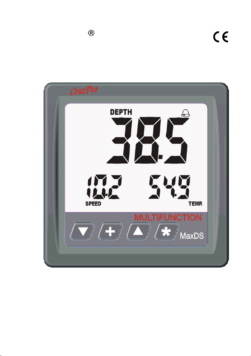
Introduction
The MaxDS110 multifunction depth/speed instrument will
simultaneously display three sets of data on three digital displays.
Depth, boat speed, sea water temperature, trip and total logs, race
timers, time-of-day, elapsed trip time and battery voltage can be
displayed in a variety of different formats. High and Low alarms can
be set for Depth (Deep and Shallow), boat speed, water temperature
and battery voltage. Eight (8) different Time-Of-Day alarms can be
set to remind you of important radio schedules, weather FAXes, etc.
The two race timers can be independently set to any value from 1 to
60 minutes.
A keel offset can be programmed to provide the depth of the water
under the keel. Variable display damping (filtering) can be selected
for both depth and boat speed. You can switch between sixteen
different predefined display configurations with the front panel
keys. Changes are automatically saved to a nonvolatile memory.
You can select from five backlight levels (including OFF) and the
backlights can be externally activated. The MaxDS110 works on
both 12 and 24 VDC and outputs NMEA 0183 data sentences for
depth, boat speed, sea water temperature and battery voltage.
A variety of different optional depth and speed/temperature
transducers are available in plastic and bronze that mount on the
transom or through the hull.
Table of contents
Other CruzPro Marine Equipment manuals


