CanDock JETROLL User manual

Créer le
2020
-
11
-
30
Approbation
Fichier
Owners manual
Révision
01
-JETROLL OWNER'S MANUAL-
Every customer purchasing a Candock product from Candock Inc. or one of its duly authorized representatives and distributors should
activate the Manufacturer's warranty of its product(s) via Candock's online warranty activation system.
Online warranty activation: http://candock.com/about-us/support-and-warranty/register-product/

120
JETROLL DRY-DOCK SYSTEM
JETROLL SYSTEM BASIC CONCEPTS
The JETROLL dry-dock system is a single-piece unit that is specially designed to accommodate PWC’s.
Consisted of a single piece of medium density polyethylene, with 100% of its interior filled with expanded polystyrene, the JETROLL is
virtually unsinkable. In opposition with the JETSLIDE, the JETROLL is equipped with 12 nylon wheels on stainless steel shafts, allowing
for even easier berthing and unberthing maneuvers. Furthermore, as it requires virtually no assembly, it offers advantages that are
not to be neglected.
Depending on the environment and the PWC at stake, Candock will determine the proper anchoring layout.
There are some basic yet, essential rules and premises to ensure a functional system:
1- CANDOCK’S PROPOSED ANCHORING CONFIGURATION SHOULDN’T BE ALTERED IN ANY WAYS.
2- USERS MUST MASTER MANEUVERS IMPLIED WITH SUCH A SYSTEM.
3-CANDOCK IS NOT LIABLE FOR ANY DAMAGES RESULTING OF THE NON-COMPLIANCE OF THE FOLLOWING GUIDELINES.

121
JETROLL (BOW-STOP, HOLE CAPS, AND WHEELS)
USEFUL LINKS AND RESOURCES:
YouTube
Website
TAB POSITIONS
SPECIFICATIONS
Material/Composition: Medium-density polyethylene resin – Roto-molded
Available colors: Beige and Gray
Dimensions: L x W: 386 cm (152”) x 193 cm (76”) H: 30.5cm (12”)
Weight: 159 kg (350 lbs.)
Needed tools: G2 key for pin, Key for nut, rubber mallet, 7/32’’ Halen key
TERMINOLOGY
JETROLL TABS: (4x) prominent threaded openings that are on the front of the JETROLL; which are located under tab “0” and under
“-1”. The 2 outside tabs are the lowest (under “-1”), and the 2 center ones are the highest (under “0”). This particularity allows for our
EDGE cubes to be merged at the front of the JETROLL. As opposed to our regular CUBE coupling system, which requires the addition
of a SLIDING NUT at the bottom of a connection point so that the CONNECTING PIN can have traction in the threads, the JETROLL also
has its threads inside the tabs.
SKU NUMBERS
JETROLL BASIC KIT BEIGE: B0363
JETROLL BASIC KIT GRAY: B0362
BOW-STOP BEIGE: B0365
BOW-STOP GRAY: B0364
HOLE CAP BEIGE: B0367
HOLE CAP GRAY: B0366
WHEELS: F0208
SHAFTS: F0202
BOW-STOP
HOLE-CAP
WHEELS AND SHAFTS

122
PLUGS: These watertight plugs are always found in the front part of the JETROLL. These plugs, made of a breathable material, act as
pressure release valves, thus preventing JETROLL’s deformation due to temperature changes and pressure variations. Furthermore,
these plugs prevent any condensation inside the JETROLL.
WHEELS & PLASTIC WASHERS: (12x) plastic and polyurethane wheels and (24x) nylon washers that can be positioned in numerous
configurations to ensure an optimal fit with any PWC on the market. Include (1x) small nylon washer on each side of each wheel for a
total of (24x) for each Jetroll.
SHAFTS: (12x) stainless shafts that allow for smooth rolling motion of the wheels.
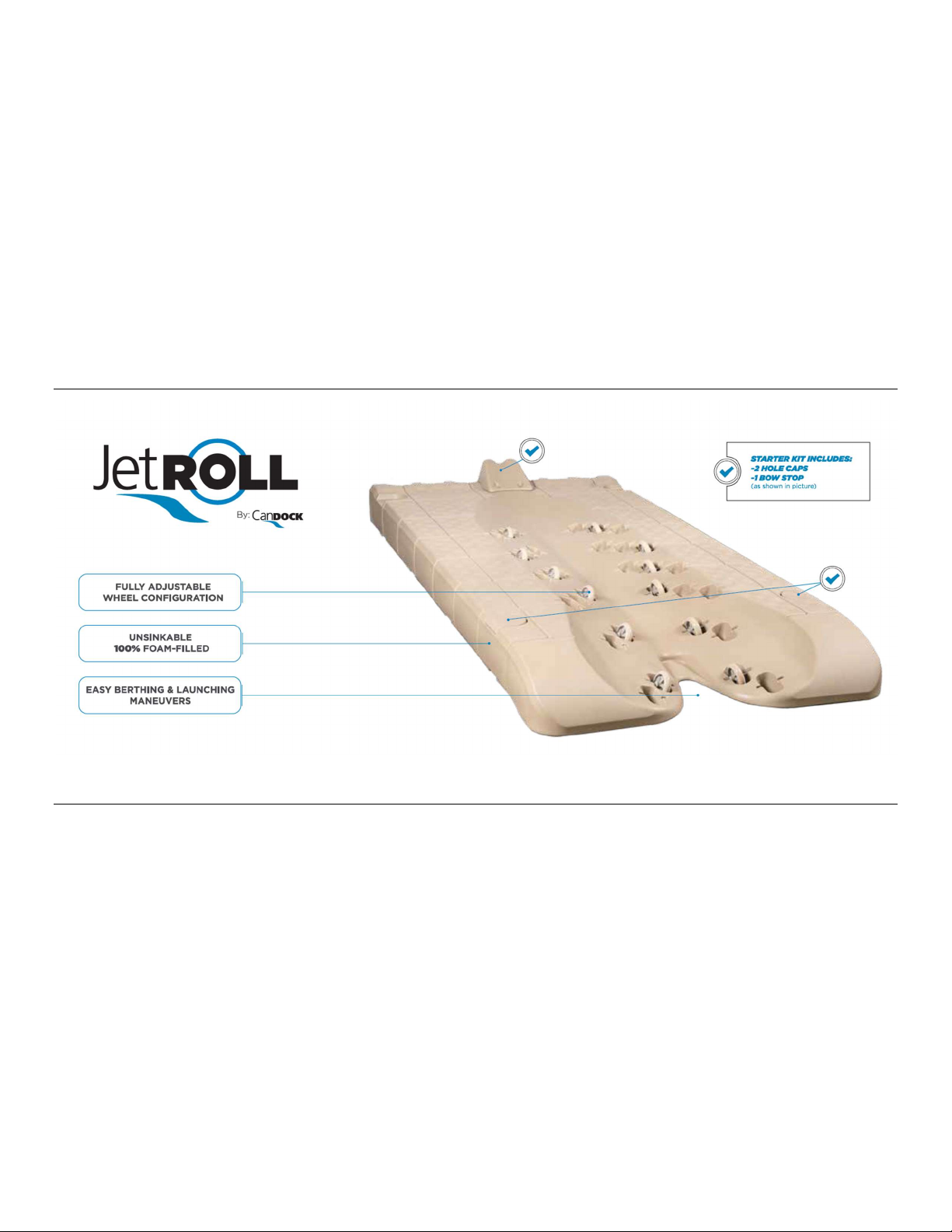
BOW-STOP: Molded plastic piece positioned at the front of the JETROLL to help prevent the PWC from exceeding the front of the
system during berthing maneuvers.
HOLE CAP: A molded plastic piece that can be “snapped-on” into the circular openings on the 4 corners of the JETROLL. Depending
and the adequate anchoring layout and accessories, these are to be inserted in the remaining openings to prevent a trip hazard.
OVERVIEW
ASSEMBLY PROCEDURE
PRIOR TO INSTALLATION
1-Assemble on a flat surface rather than water.
PROCEDURE:
1-Prepare the needed parts around your JETROLL (2 HOLE CAPS, 1 BOW-STOP, and 12 WHEELS AND SHAFTS).
2-Determine the location of the 12 wheels. Ideally, Candock advocates using the featured pre-set (above image). The goal is to create
a lower area to create a cradle for the machine to rest in the system's middle. Especially after/during berthing maneuvers, this lower-
center geometry is highly appreciated to prevent the PWC from rolling back in the water by itself.
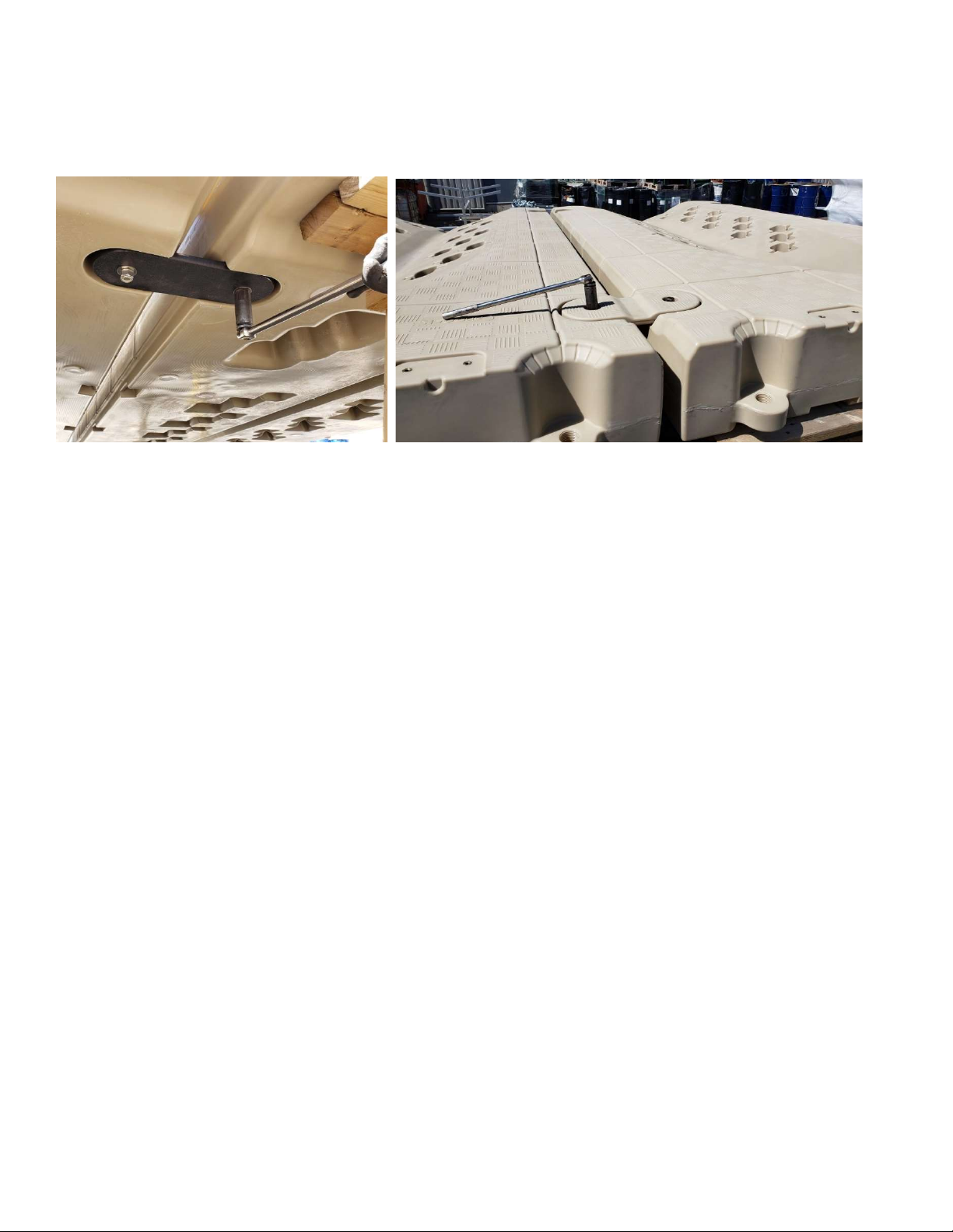
3-Using the rubber mallet, hammer down the wheels and shafts assembly with a single stroke motion, directly on the wheel.
4-Secure the BOW-STOP using the provided hardware. Brass inserts are already casted in the plastic of the unit.
5- If needed, using the rubber mallet, hammer down HOLE-CAPS in the proper locations.

123
OPERATING A WATER-CRAFT WITH THE JETROLL
IMPORTANT NOTICE
The water depth at the back of the JETROLL must be at least 1m (3.3’) to avoid potential damage to the PWC turbine.
GOING UP THE SYSTEM
Approach the JETROLL at idle, keeping the craft straight and centered with the JETROLL. When the craft's bow is in contact with the
JETROLL, give small throttle strokes to make the craft align with the JETROLL. When the craft is in line with the JETROLL, throttle in
slowly. After a few tries, you will rapidly develop a feel of how much throttle you must use to reach the final position on the JETROLL
NOTE: It is recommended to secure the craft to the BOW-STOP’s eyelet to prevent the PWC from rolling back into the water
accidentally.
GOING DOWN THE SYSTEM
To go back into the water, initiate the procedure by pushing the PWC backward of 30-60cm (1’ to 2’) to bring the machine's weight
towards the back of the system. Then, stand up at the back of your PWC, grab the seat's handle, and transfer your weight backward.
The easiest way to push the PWC backward is to grab the PWC's nose in one hand and the handle with the other and then push gently.
Be vigilant because, at some point, your PWC will want to go down by itself. At this point, you will have to promptly get on the machine
if you do not want your watercraft in the water without you.
WARNINGS & SPECIAL INSTRUCTIONS
1- For all JETROLL systems, the surrounding environments must not be subjected to waves of more than 60cm (24’’). We recommend
installing a JETROLL system in a protected area.
2-Surfaces can be slippery when the system is wet.
3-All PWCs must be entirely brought for the front of the JETROLL at all times.

124
LINK-KITS
SPECIFICATIONS
Material/Composition: HDPE and SS 316 L
Available colors: Beige and Gray
Needed tools: 15/16’’ ratchet socket and wrench
TERMINOLOGY
UPPER LINK: Rotomolded plastic piece that fills the voids of the piling openings on the JETROLLS.
THREADED ROD AND HARDWARE: SS 316 and brass hardware to link the upper and lower link parts together.
LOWER LINK: HDPE plate fitted underneath the Jetroll allows for a complete assembly of the LINK KIT.
OVERVIEW
The addition of LINK KITS between multiple JETROLLS may be suggested or mandatory depending on the environment and
conditions the systems are to be installed in. Please refer to your Candock distributor to know if LINK KITS should be included on
your system. The addition of LINK KITS provides a stiffer assembly and prevents the JETROLLS from moving/sinking independently.
ASSEMBLY PROCEDURE
PRIOR TO INSTALLATION
Position the JETROLLS in the water at their final location before installing the LINK KITS
One person should be standing on the JETROLLS with one tool, and the other person should be in the water with the other tool to hold
the “bottom” hardware.
SKU NUMBERS
LINK KIT BEIGE: B0369
LINK KIT GRAY: B0368

125
PROCEDURE:
1-Position the upper and lower links onto the JETROLL connection point.
2-Insert threaded rods with washers from the top.
3-Place and hold the lower link underneath the JETROLLS

126
3-Insert the lower hardware and hold it in place while the person on the JETROLLS screws the threaded rod in place.

127
EXTENDED CONNECTING PINS FOR JETROLL
SPECIFICATIONS
Material/Composition: High-density polyethylene
Available colors: Beige and Gray
Dimensions: L :26.6cm x W: 17.2 cm (6.88”) / Shaft diameter : 4.547 cm (1.819”)
Weight: 377g
Needed tools: G2 key for pin
TERMINOLOGY
HEAD: Upper part of the CONNECTING PINS designed with a flat and anti-skid surface.
NOTCH: Manufactured recess in the pin’s head that allows the tool to insert the key for screwing and unscrewing.
SHAFT: The male part of our coupling system, the extended threaded shaft, is inserted in the JETROLL’s front tabs.
ASSEMBLY PROCEDURE
1-Initiate the rotating process by hand.
2-When the CONNECTING PIN has access to the JETROLL’s tab threads, proceed by screwing manually or mechanically with the
proper tools.
3-Make sure to securely tighten the CONNECTING PINS until snug, without over-tightening them.
TIPS
1-When initially inserting the CONNECTING PINS in place, you might want to firmly “tap” the pin in place. You ensure a firm “initial”
grip of the shaft threads into the tabs by proceeding so. Likewise, this “tap” helps you get the pin through the cube’s tabs resting on
top of the JETROLL’s tabs.
2-Once the assembly process is completed, align the NOTCHES of the CONNECTING PINS using the manual key. This simple operation
allows to quickly locate any CONNECTING PINS which could have unscrewed over time.
3-Always proceed with caution if using a power drill to fasten the CONNECTING PINS; the drill can tend to “kick”. Use protective
footwear. If using a power drill to unscrew pins, always loosen-up the pins manually before using the drill.
4- Never use an ‘’impact tool’’ to fasten the connecting pins as you will most likely damage the connecting pins as well as the assembly
key for drill.
SKU NUMBERS
EXTENDED CONNECTING PIN BEIGE: A0093
EXTENDED CONNECTING PIN GRAY: A0094

128
PWC JETROLL SYSTEM CONFIGURATION GUIDELINES
The following section is also essential to Candock. Indeed, the configuration of a PWC Jetroll system is of the utmost importance to
ensure its optimal durability and performance. Thus, following the below recommendations and guidelines is vital for your product
to perform as we intend.
There are several sizes and models of PWCs, so the below configurations may have to be modified on a case-by-case basis. Please
contact a Candock representative in the event you wish to alter the below configurations.
IMPORTANT NOTIONS
-Always keep the rear (entry point) of the JETROLL free for it to sink freely when the PWC is climbing onto the system.
-For multiple units assembled, LINK KITS may or may not be suggested. The overall exposure and application influence the inclusion
or exclusion of LINK KITS. Always refer to your Candock representative for guidance.
-Upon completion of an installation, HOLE CAPS or LINK KITS are mandatory in all 4 pile openings of the JETROLL(s) to ensure a safe
and “trip-hazard-free” environment.
-BOW STOPS are mandatory on all JETROLLL installation
-The inclusion of 12 wheels is mandatory on all JETROLL
-The ideal wheel configuration may vary depending on the hull’s shape and machine size.

129
PWC JETROLL SYSTEM ANCHORING GUIDELINES
The following configurations are showcased to help determine the best scenario for each situation. The number of factors that
influence the exact suggested layout is numerous, so the following proposed layouts must not be taken integrally. Modifications and
altering of these are highly probable. Please contact a Candock representative to gather clarification and validation on the below
configurations.
The below section is segmented as per our anchoring accessories/techniques categories. Note that combinations of multiple
techniques may or may not apply, and some alterations of the below accessories/techniques may also be involved in the process. The
below list aims at covering as many of the possible scenarios. If the Jetroll system is secured against another floating or fixed structure
(another Candock system, a regular floating dock, a fixed dock, or seawall), this “other” structure must be adequately anchored or
fixed in place to withstand the torque that the addition of the Jetroll will apply.
STAND ALONE
ANCHORING WITH
PILES & PVC
SLEEVES
ANCHORING WITH
SWIVEL ANCHOR
CHANNELS
ANCHORING WITH
ANCHORING
STRUTS
(LENGTH 5’ MAX)
CONNECTED TO A
CANDOCK WITH
(4X) EXTENDED
CONNECTING PINS +
(12x) SPACERS
ANCHORING WITH
2 7/8’’ STEEL PILES +
PVC SLEEVES AND
UPPER PILE SECTION
FASTENING
ACCESSORIES
CANDOCK
FIXED FLOATING FIXED
Table of contents
Other CanDock Marine Equipment manuals
Popular Marine Equipment manuals by other brands

Lone Star Marine
Lone Star Marine HAULMASTER 1500 quick start guide

Garmin
Garmin GMI 20 owner's manual

Raymarine
Raymarine LIGHTHOUSE 4 Operation instructions

Crow
Crow FW2-NEPTUNE-8F instruction manual

TOHMEI
TOHMEI ANTI ROLLING GYRO ARG175T Operation instructions

KVH Industries
KVH Industries TracPhone F33 user guide