Kolver K-DUCER KDU-NT User manual

KDU-NT and KDS-NT*
Torque range: 5 – 70 cNm, 7 – 100 ozfin
OPERATOR
MANUAL
*Patent pending

Vers. 111422 2
IDENTIFICATION DATA OF THE MANUFACTURER
KOLVER S.r.l.
VIA M. CORNER, 19/21
36016 THIENE (VI) ITALIA
IDENTIFICATION DATA OF THE PRODUCT
Code
Model
Torque
(Nm)
Speed (rpm)
Min
Max
033001
KDU-NT
165050
KDS-NT70
0.05 – 0.70
10
700
165050/HM
KDS-NT70/HM
0.05 – 0.70
10
700
165150
KDS-NT70CA
0.05 – 0.70
10
700
165150/HM
KDS-NT70CA/HM
0.05 – 0.70
10
700
TECHNICAL DATA OF THE PRODUCT
KDU-NT controller
KDS-NT (patent pending) screwdriver
FUSE: 2,00 A internal
FUSE: none
DIMENSIONS: 184 x 169 x h69 mm
DIMENSIONS: Ø 30 x 223 mm
WEIGHT: 1,22 Kg
WEIGHT: 320 g
POWER SUPPLY: 100÷240 V AC 50÷60 Hz
POWER SUPPLY: 40V DC
TENSION: 40V DC
TENSION: 40V DC
POWER: 12.5 W
POWER: 12.5 W
NOISE LEVEL: < 70 dB(A)
VIBRATION LEVEL: < 2.5 m/s²
DECLARATION OF CONFORMITY
KOLVER S.r.l. declares that the new tool here described: control unit model KDU-NT and
screwdrivers KDS-NT series (see table) are in conformity with the following standards and
other normative documents: 2006/42/CE, LVD 2014/35/UE, EMCD 2014/30/UE, EN 62841-2-
2:2014, EN 62841-1: 2015, EN 60204-1, EN 61000-6-2, EN 61000-6-4, 2011/65/UE (RoHS III).
Name: Giovanni Colasante
Position: General Manager
Person authorized to compile the technical file in Kolver
Thiene, January 1st 2022 Giovanni Colasante

Vers. 111422 3
DECLARATION OF USE
Screwdriver (class I) suitable for industrial environment only. It shall be used for
tightening. No other use will be permitted. For professional use only.
WARNING: To reduce the risk of injury, before using or servicing screwdriver, read and
understand the following information as well as separately provided safety instructions
(item code: 0MS000). The features and descriptions of our products are subject to change
without prior notice.
DECLARATION OF NOISE AND VIBRATION EMISSION
NOISE LEVEL: < 70 dB(A)
VIBRATION LEVEL: < 2.5 m/s²
These declared values were obtained by laboratory type testing in compliance with the stated
standards and are not adequate for use in risk assessments. Values measured in individual
work places may be higher than the declared values. The actual exposure values and risk of
harm experienced by an individual user are unique and depend upon the way the user
works, the work piece and the workstation design, as well as upon the exposure time and the
physical condition of the user. We, KOLVER, cannot be held liable for the consequences of
using the declared values, instead of values reflecting the actual exposure, in an individual
risk assessment in a work place situation over which we have no control.
OPERATING MODE
The screwdriver can be manual or used as fixed spindle on an automatic machine.
CONTROL UNIT
Power source by KDU-NT series.
MAINTENANCE INSTRUCTIONS
Maintenance should be performed by qualified personnel only.
•Prior to any maintenance task: disconnect the screwdriver.
•When disassembling / reassembling the screwdriver, take the following precautions:
-Check that the controller is switched off.
-Disconnect the cable.
According to Directive 2012/19/EU concerning Waste Electrical and Electronic Equipment
(WEEE), this product must be recycled.

Vers. 111422 4
Table of Contents
DECLARATION OF USE...............................................................................................................3
INTRODUCTION ...............................................................................................................................6
MODELS...............................................................................................................................................6
INSTALLATION .................................................................................................................................7
Installation of KDU-NT unit..........................................................................................................7
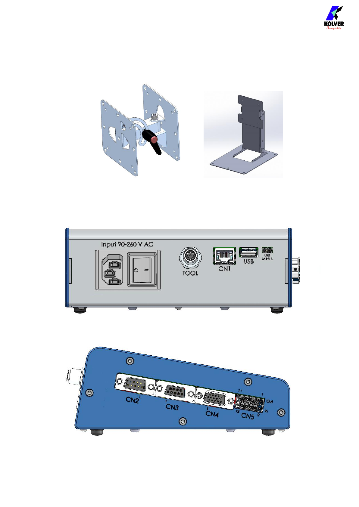
Connectors .......................................................................................................................................8
Installation of KDS screwdriver..................................................................................................10
Lever installation.......................................................................................................................10
Cable connection and part numbers ......................................................................................11
Installation of reaction arm......................................................................................................11
Installation on a fixture ............................................................................................................11
QUICK START...................................................................................................................................14
TERMINOLOGY ...............................................................................................................................17
OPERATING THE KDS SCREWDRIVER .....................................................................................19
OPERATING THE K-DUCER CONTROL UNIT.........................................................................21
Main Screen – Program Mode – navigation tree ......................................................................21
Main Screen – Program Mode.....................................................................................................22
Main Screen – Sequence Mode – navigation tree .....................................................................24
Main Screen – Sequence Mode....................................................................................................25
Torque and Angle graphing ........................................................................................................27
Visualizing the Torque and Angle charts ..............................................................................27
Interpreting the Torque and Angle charts.............................................................................28
Torque and Angle charts with Running Torque ..................................................................29
Determining the joint type...........................................................................................................30
Determining the appropriate program settings .......................................................................31
Hard/inelastic joints..................................................................................................................31
Soft/elastic joints........................................................................................................................31
Screwdriving Phases.....................................................................................................................32
Retrieving and storing the screwdriving results......................................................................33
Connecting a barcode scanner ....................................................................................................35
Connecting a bit-tray or switchbox (CBS880, SWBX88)..........................................................35
CONFIGURING THE K-DUCER ...................................................................................................37

Vers. 111422 5
ADVANCED TORQUE CONTROL STRATEGIES ..................................................................37
RUNNING TORQUE ...............................................................................................................37
PREVAILING TORQUE...........................................................................................................40
MULTI-STEP AND COMBINED PROGRAMS ....................................................................41
MAIN MENU ................................................................................................................................42
PROGRAMS menu .......................................................................................................................43
PROGRAMS menu tree............................................................................................................44
TORQUE & ANGLE menu ......................................................................................................48
RAMP, TIME, & PV TORQUE menu.....................................................................................50
REV & PRE-REV menu ............................................................................................................53
OTHER menu ............................................................................................................................54
SEQUENCE SETTINGS menu ....................................................................................................57
SEQUENCE SETTINGS menu tree.........................................................................................58
CURRENT SEQ. menu .............................................................................................................59
GENERAL SETTINGS menu.......................................................................................................61
USB menu.......................................................................................................................................66
FREE K-EXPAND NT SOFTWARE ............................................................................................69
REMOTE CONTROL INTERFACES..............................................................................................70
24V I/O............................................................................................................................................71
Pinout (CN5)..............................................................................................................................72
MODBUS TCP ...............................................................................................................................76
PROFINET / Ethernet IP / EtherCAT / others ...........................................................................79
MAINTENANCE AND CARE........................................................................................................80
CALIBRATION..............................................................................................................................80
EXPLODED VIEWS AND SPARE PARTS:....................................................................................81
GUARANTEE....................................................................................................................................89

Vers. 111422 6
INTRODUCTION
K-DUCER NT is the new class A low torque intelligent transducerized assembly system
from Kolver.
Thanks to a sophisticated control system, the electronic circuit communicates with KDS-NT
(Patent pending) series screwdriver equipped with integrated torque/angle transducer and
allows to stop the screwdriver instantly when reaching the preset torque or angle.
The AC 90÷260V - 50÷60Hz power supply is converted into 30VDC required by the
screwdriver through a switching board.
IMPORTANT: K-DUCER NT is a highly accurate unit, but it is critically important to select
the appropriate settings to ensure that the desired and proper torque is being applied and
that the screwdriver motor works efficiently. Read the manual carefully and if unsure
please contact Kolver for support.
MODELS
KDU-NT power supply and control unit:
Code
Model
Features
033001
KDU-NT
5” touch screen
64 programs and 8 sequences (jobs)
multiple parameters, total job flexibility
Torque and angle charts
RJ45 ethernet connector providing
Modbus TCP (server)
12-24V NPN I/O (6 inputs – 6 outputs)
2x RS-232 serial ports
1D and 2D barcode scanner compatibility
KDS-NT (Patent pending) series electric screwdrivers with torque and angle transducer
(HM = half-moon bit holder):
Code
Model
Torque
(Nm)
Speed (rpm)
Min
Max
165050
KDS-NT70
0.05 – 0.70
10
700
165050/HM
KDS-NT70/HM
0.05 – 0.70
10
700
165150
KDS-NT70CA
0.05 – 0.70
10
700
165150/HM
KDS-NT70CA/HM
0.05 – 0.70
10
700

Vers. 111422 7
INSTALLATION
Installation of KDU-NT unit
The KDU-NT features rubber feet and a tilted screen and can be conveniently set on a flat
surface. All dimensions are reported in mm.

Vers. 111422 8
Also available separately:
•vertically and horizontally adjustable bracket (part number 010401)
•swivel table stand (part number 010402)
010401 010402
Connectors

Vers. 111422 9
TOOL connector
To connect a KDS-NT (Patent pending) series screwdriver. Take care to respect the
alignment tabs on the connector. See Installation of KDS screwdriver section for
instructions on connecting the screwdriver.
CN1 ethernet connector RJ45
To connect using MODBUS TCP, or K-Expand from a PLC, PC, or server. Refer to the
REMOTE CONTROL INTERFACES chapter.
USB A
Plug in a FAT32 formatted flash drive to automatically save screwdriving results and
backup all settings. Refer to the Retrieving and storing the screwdriving results and USB
menu sections.
USB mini B
To connect using K-Expand software. Refer to the K-EXPAND software chapter.
CN2 male serial connector
To connect with a compatible barcode scanner, such as Kolver Barcode P/N 020050, serial
printers such as Kolver PRNTR1, or serial terminals (PC/PLCs).
CN3 female serial connector
To connect with Kolver accessories SWBX88/CBX880, serial printers such as Kolver
PRNTR1, or serial terminals (PC/PLCs).
CN4 female serial connector
Reserved for servicing the unit.
CN5 I/O connector
To connect with 24V I/O functionality such as PLCs, pedals/buttons, LEDS, etc. Refer to the
REMOTE CONTROL INTERFACES chapter.

Vers. 111422 10
Installation of KDS screwdriver
Lever installation
To install the lever kit (cod. 010450), simply remove the two M2.5 screws from the cover
(cod. 250203), place the lever on top of the cover, and screw using the longer M2.5 screws
provided with the lever kit.

Vers. 111422 11
Cable connection and part numbers
The following cables are available for the K-Ducer NT system:
-part number 2500363 (8-pin M12 8ft cable)
To connect the screwdriver to the unit:
1. insert the male connector into the appropriate TOOL connector on the bottom of the
unit, taking care to respect the alignment tabs. Push the connector in gently and turn
the threaded nut clockwise.
2. insert the female connector into the appropriate connector at the top of the
screwdriver, taking care to respect the alignment tabs. Gently push the connector
into its position and turn the threaded nut clockwise.
Always hand-tighten the connection (avoid tools or wrenches) and do not overtighten.
To disconnect the cable:
1. lightly push the connector in towards the screwdriver (or the controller)
2. turn the threaded nut counterclockwise
3. pull the connector out
If necessary, you can connect and disconnect the screwdriver cable while the KDS-NT unit
is powered on. The KDS-NT will recognize a disconnected or recently connected
screwdriver and display a message.
Installation of reaction arm
Kolver recommends always using a reaction arm to increase the precision of low torque
tightenings and for the comfort of the operator.
Fix the reaction arm to the indicated areas only, on the naked metal cylinder near the head
of the screwdriver.
Warning: do not connect the reaction arm anywhere other than the above designated areas.
Fixing the reaction arm to the middle of the screwdriver handle will squeeze the
screwdriver shell, causing damage to the internal components, and failing to absorb the
torque reaction safely and reliably.
Installation on a fixture
The KDS-NT can be mounted on a fixture via the three threaded M3 holes at the head of the
screwdriver.
The CA models for automation also offer three threaded M3 holes on the side of the body
of the screwdriver. Refer to the drawing below.

Vers. 111422 12
Reaction arm mounting:
Example of collaborative robot mounting (threaded tool-holders also available):

Vers. 111422 13
Threaded M3 fixturing holes (side holes on CA models only):

Vers. 111422 14
QUICK START
Turn the unit on through the on/off switch on the lower panel. The unit will carry a general
system check and the words “NO SCREWDRIVER CONNECTED” will appear if no
screwdriver is connected.
You can still enter the main menu without any screwdriver connected.
When a screwdriver is connected, it will be recognized by the unit and the "CONNECTED
SCREWDRIVER" screen will appear for a few seconds, also showing the model and serial
number.
All information pertaining to the connected screwdriver can also be retrieved in the General
Settings menu.

Vers. 111422 15
If the parameters set in the current program are outside the allowable range of the
connected screwdriver, the following screen will appear:
To resolve the error, select a program previously configured for the connected screwdriver
model, or enter the main menu to modify the parameter out of range for the current
program.
The “Program parameter error” messages can be the following:
TorqueTargOverMax
Target torque higher than the allowed limit for the
screwdriver.
SpeedTargOverMax
Target speed higher than the limit allowed for the
screwdriver.
SpeedTargUnderMin
Target speed less than the limit allowed for the
screwdriver.
DownshiftTorqueOverTarg
The fast phase torque setting is higher than the final target
torque.
DownshiftSpeedOverMax
The speed of the fast phase of this program is higher than
the maximum allowed by the screwdriver.
DownshiftSpeedUnderMin
The speed of the fast phase of this program is less than the
minimum allowed by the screwdriver.
DownshiftSpeedUnder
FinalSpeed
The speed of the fast phase is lower than the final speed
(slow phase speed).
DownshiftInside
RunningTorque
The Downshift Threshold falls inside the Running Torque
Window.
TorqueMaxOverMaxLim
The Torque Target or Torque Max values are higher than
the limit for the connected screwdriver.

Vers. 111422 16
TorqueMaxUnderMinLim
In angle control: the maximum torque set in the program is
equal or lower than the minimum limit of the screwdriver.
In torque control: The maximum torque set in the program
is equal or lower than the target torque already set.
TorqueMinOverMaxLim
In angle control: the minimum torque set in the program is
equal or higher than the maximum torque already set.
In torque control: the minimum torque set in the program
is equal or higher than the target torque already set.
RevTorqueOverMax
The reverse torque of this program is higher than the
maximum torque of the screwdriver.
RevSpeedOverMax
The reverse speed is higher than the maximum allowed by
the screwdriver.
RevSpeedUnderMin
The reverse speed is lower than the minimum allowed by
the screwdriver.
RunningTorqueOverMax
In running torque – compensate mode, the sum of the max
running torque and the target torque is higher than the
maximum torque of the screwdriver.
In running torque – monitor mode, the max running torque
is higher than the maximum torque of the screwdriver.
If the connection with the screwdriver is successful, the main screen will be displayed, and
the screwdriver will be ready for work.
Connect a thumb drive on the USB-A port (the larger USB port) to automatically save each
screwdriving result.

Vers. 111422 17
TERMINOLOGY
KDU/K-DUCER/control unit: the KDU-NT control unit
KDS/screwdriver: the transducerized screwdriving tool to be used with the KDU control
unit
Transducer: electronic component installed inside the KDS screwdriver which measures
the torque in real time
Tightening: the screwdriving cycle, from start (pressing of the lever or initiating remote
lever control), to finish (automatic motor stop or lever or remote lever control release,
whichever happens first)
Rundown: the portion of the tightening cycle before reaching the seating point (the point
where the screw or bolt head touches the assembly)
Seating point: the point of the tightening at which the head of the fastener touches the
assembly, marked by an increase in the torque rate (steeper torque-angle slope) and
marking the end of the rundown phase.
Torque: rotational force
Closing torque: the last torque value measured when the screwdriver motor stopped or
when the screwdriver lever or remote lever control was released.
Running torque: the peak or average torque value encountered during the rundown phase,
before reaching the seating point.
Clamping torque: the closing torque minus the running torque. This is, theoretically, the
only portion of the closing torque that generates a clamping force from the fastener.
Target torque: the closing torque that the system will target (torque control mode only),
resulting in a “Screw OK” result if successful. In Running Torque – Compensate mode, the
system targets a Clamping torque equal to the target torque, instead of a closing torque.
Prevailing torque: an optional phase of the tightening during which the applied torque is
allowed to reach the maximum torque achievable by the screwdriver.
Torque control mode: a tightening where the screwdriver motor automatically stops upon
reaching the target torque

Vers. 111422 18
Angle: the revolutions of the tip of the screwdriver, in degrees. The starting point of the
angle measurement depends on the settings chosen.
Target angle: the angle measurement upon which the screwdriver motor will stop (angle
control mode only), resulting in an “Angle OK” result if successful
Angle control mode: a tightening where the screwdriver motor automatically stops upon
reaching the target angle
Run time: the duration of the tightening, in seconds
Run time mode: a tightening where the screwdriver motor automatically stops at the
desired run time
Program/batch: a set of one or more screws sharing the same parameters (torque, angle,
speed, barcode, etc)
Program number: the identifier of one of the 64 configurable programs (1 to 64)
Current program: the program currently selected for tightening
Program mode: in this mode, the unit works according the selected program
Sequence/Job: an ordered set of up to 16 programs, with the option to define how to
transition between programs
Sequence letter/number: the identifier of one of the 8 configurable sequences (A to H)
Current sequence: the sequence currently selected for tightening
Sequence mode: in this mode, the unit works according to the selected sequence
OK/NOK: the result of the tightening. OK: tightening finished respecting all of the
configured parameters. NOK: tightening finished without respecting one or more of the
configured parameters.
Running torque mode: an optional phase of the tightening during which the peak or
average torque value is measured, and then added to the torque target in real time for the
current tightening.

Vers. 111422 19
OPERATING THE KDS SCREWDRIVER
Warning: Kolver strongly recommends using a reaction arm when applying torques lower
than 0.30 Nm, to improve the precision of the torque applied by eliminating any effect and
impulse from the operator’s wrist.
(1) Lever
Press and hold the lever to initiate a tightening.
The screwdriver will automatically stop according to the configured program, in either
an OK or a NOK state, depending on the success of the tightening.
The screwdriver will also stop if the lever is released in the middle of the tightening,
and either return to the READY state or raise the NOK state if the LEVER ERROR
option is active for the current program (Programs menu > Other > LEVER ERROR).
Note: KDS series screwdrivers sizes 20Nm and above provide a “START” button instead
of a lever. The functionality remains the same.

Vers. 111422 20
(2) Reverse button
Press and hold the button to initiate a defix run, rotating in the opposite direction of the
selected direction of rotation for the lever (see Programs menu > Other > ROTATION ).
The behavior of the reverse button can be changed from the general settings menu
(General Settings > REVERSE BUTTON).
(3) LEDs
The two LEDs indicate the state of the screwdriver:
Blinking white: the screwdriver was just connected to the K-DUCER
control unit
Off: the screwdriver is ready, or the screwdriver is not connected
Solid green: the last screw result was OK
Solid red: the last screw result was NOK
Solid blue: screwdriver is running in the tightening direction, either via
the lever or via remote control
Solid purple: the screwdriver is running in the de-fix direction, either via
the reverse button, or via remote control
Blinking purple: the reverse button is in switch mode and is activated. The
screwdriver is ready to run in de-fix rotation via the main lever.
(4) Reaction arm connections
Fix the reaction arm to one these areas only, and never anywhere else on the
screwdriver.
(5) Hanging hook
To hang the screwdriver somewhere easily accessible in the operator’s workbench.
(6) Female connector
To connect the screwdriver to the KDU-NT control unit.
(7) Bit Holder
¼” Hex spring-loaded power-tool bit holder (non /HM models only)
Half-moon spring-loaded power-tool bit holder (/HM models only)
Push the outer cylinder in towards the screwdriver to release the lock to insert or
remove the desired bit.
This manual suits for next models
10
Table of contents
Other Kolver Industrial Equipment manuals
Popular Industrial Equipment manuals by other brands

MinerDude
MinerDude 8XTREME PLUS troubleshooting guide

Siemens
Siemens SIMATIC CP 4163-5 operating instructions

Xebec
Xebec XP-AUT06M user manual

MGF
MGF S80 SPREADER BEAM user guide

lancer
lancer BEV85 Work Instruction

Akron
Akron 3430 Installation, Operating and Maintenance Instructions for the Installer and the User

Siemens
Siemens simovert EMC-Filter Compact PLUS operating instructions

Klimawent
Klimawent ERGO-L/Z-2/Ex Use and maintenance manual

M-system
M-system M8BS-16K2 instruction manual

Abbey Machinery
Abbey Machinery VF1500T Maintenance, Operating Instructions and Spare Parts Lists

ABB
ABB Dodge Quantis BU383 manual

Bitzer
Bitzer 4GFC Maintenance instructions