Kolver LINAR2 User manual

Folding and Linear Positioning Arms with Autoadvance Kit
Manual
UIDENTIFICATION DATA OF THE MANUFACTURER
KOLVER S.r.l.
VIA M. CORNER, 19/21
36016 THIENE (VI) ITALIA
UIDENTIFICATION DATA OF THE PRODUCT
MODEL:
LINAR2
TLS1/LINAR2
CODE:
010682/A
010682/TLS1/A
Only Autoadvance kit to be installed on Kolver code 020099
TECHNICAL DATA OF THE PRODUCT
ELECTROVALVE TENSION: 24V DC 0,35W
ARM DIMENSIONS: 684 x 191.13 x 722,5h mm
ARM WEIGHT: 5,7 Kg
AUTOADVANCE KIT WEIGHT 0,4 Kg
Code
Model
Torque
Max
Stroke mm
Piston stroke
mm
Min distance
between screws at
the max arm
extension
Min
Max
010682/A
LINAR2 with
Autoadvance kit
50 Nm
184
665
0-50
010682/TLS1/A
TLS1/LINAR2 with
Autoadvance kit
50 Nm
184
665
0-50
6 mm

Vers. 210422 2
Autoadvance Kit
The Autoadvance arm kit is a particular device that mounted on a Kolver
Linar2 or Linart arm helps the operator in the assembly of self-tapping
screws or in case of strong axial thrust.
Through a pneumatic piston, the part of the arm that supports the
screwdriver is pushed down to help the axial thrust on the screw. The
pneumatic piston is piloted by a electrovalve which, when properly
powered, will push the piston (see the section dedicated to electrical
connections).

Vers. 210422 3
AUTOADVANCE KIT EXPLODED VIEW

Vers. 210422 4
SPARE PARTS
Position
DESCRIPTION
Code
Qty
1
RACCORDO SILENZIATORE
895094
2
2
ELETTROVALVOLA
895092
1
3
SUPPORTO ELETTROVALVOLA
895096
1
4
VITE M3x10
231530
2
5
RACCORDO ARIA 90° M5 TUBO 4MM
250073
3
6
ANELLO DI TEFLON AUTOAVANZANTE
895084
1
7
BOCCOLA DI GUIDA AUTOAVAZANTE
895080
1
8
MOLLA INTERNA AUTOAVANZANTE
895088
1
9
PERMAGLIDE AUTOAVANZANTE
895091
2
10
TUBO 4MM
250075
1
11
CILINDRO 12MM CORSA 50MM DOPPIO
EFFETTO
895090
1
12
ANELLO FISSAGGIO PISTONE
895083
1
13
M5X14 BRUNITA
895021
2
14
SUPPORTO PISTONE
895087
1
15
CUFFIA TEFLON
895085
1
16
VITE M3X5
801003
4
17
ANELLO DI APPOGGIO
895086
1
18
M3 X 8
240005/ZN
4
19
GUIDA SFERE AUTOAVANZANTE
895082
1
20
REGOLATORE UNIDIREZIONALE
895093
2
21
SFERA DIAM. 3mm
200003
6
22
BOCCOLA DI BLOCCAGGIO
895081
1
23
VALVOLA CHIUSURA ARIA
895095
1
24
VITE M8 X 16
895019
1
25
CAVO ELETTROVALVOLA 2M
895092/2M
1

Vers. 210422 5
Electrovalve Specifications

Vers. 210422 6
Fluid
Air
Operating pressure
0,15 –0,7 MPa
Ambient and fluid temperature
-10 - 50 °C
Max operation frequency
10 Hz
Pilot exhaust method
Common exhaust type
Lubrification
Not required
Impact/vibration (m/s²)
150/30
Enclosure
Dust proof
Terminal
IP65
Coil rated voltage
24 V ±10%
Power consumption
0,35 W
Response time
Max 13 ms

Vers. 210422 7
Electrical connection
Connect the supplied cable (code 895092/2M) to the electrovalve
through the appropriate connector.

Vers. 210422 8
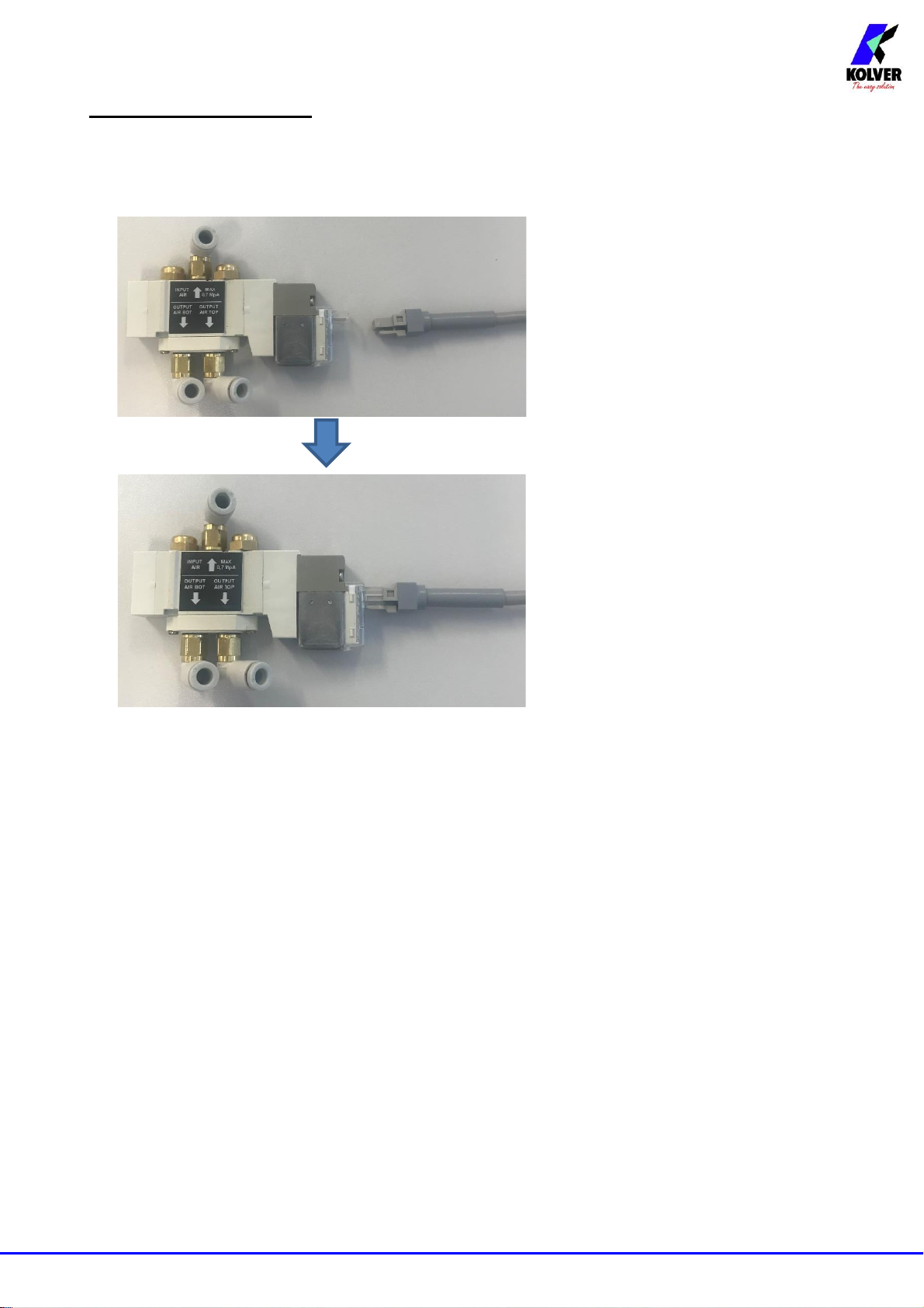
Cable between the control unit and the electrovalve
Cable 2 mt to connect the per connessione elettrovalvola cod.
895092/2M.
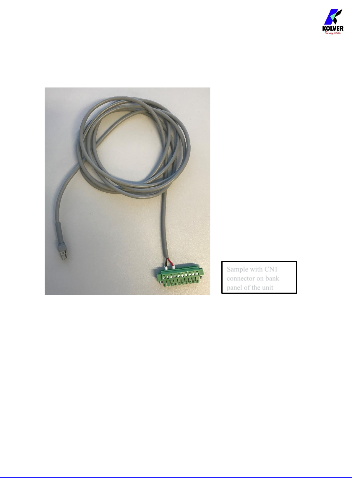
The 2 mt cable for connection to the electrovalve (code 895092/2M), it
is supplied with a moulded electrovalve connector on one side and 2
wired pin on the opposite side. The red cable must be connected to the
24V “lever / W” or “Motor ON” signal present in the Output connectors
of the Kolver units; while the black one will be connected to the common
0VDC.
NB: some unit models have specific output signals for use with a self-
advancing arm called “Lever / W”.
Sample with CN1
connector on bank
panel of the unit

Vers. 210422 9
I/O Kolver unit connection to advance arm
Model
Code
Electrovalve cable
+24V Red wire
Electrovalve cable
0V Black wire
EDU 1FR/SG/W
010010/FR/SG/W
Pin 6
Pin 1
EDU 1BL/SG/W
003000/SG/W
Pin 7
Pin 9
EDU 2AE Series
Pin 4 CN1
Pin 2 CN1
KDU Series
Pin 42 CN3
Pin 44 CN3
LEVER START
LEVER REVERSE
MOTOR START
TORQUE SIGNAL
PILOT VALVE

Vers. 210422 10
Cylinder

Vers. 210422 11
Force
1 decaNewton [daN] = 10 N
1 decaNewton [daN] = 1,02 Kgf

Vers. 210422 12
Mounting
Insert the pneumatic cylinder into the hole of the fixing ring.
Secure the cylinder with the 22mm nut, keep the pneumatic fittings aligned
laterally as shown in the figure.

Vers. 210422 13
Connect the cylinder to the push bracket.
Fix the stem to the bracket up to the stop using the 5mm wrench. Secure the
lock nut with a 10mm wrench.

Vers. 210422 14
Place the bushing on the vertical bearing support.
Join the assembled kit to the arm holder plate.

Vers. 210422 15
Align in the cylinder holder the fixing holes to the holes in the arm holder
plate. Then fasten the screws.
Insert the kit mounted on the sliding rod.

Vers. 210422 16
NB. In order to move manually the self-advancing block in the rod it is
necessary to keep it pressed on the vertical bearing support in order to
simulate the closing of the piston. If no pressure is exerted, the self-
advancing block does not allow the arm to slide upwards. When the arm is
in the rest position, the piston must remain closed so that the two parts are
kept in support.
Arm in locked position
Piston in the push phase
Arm free to slide
Piston closed in the rest position

Vers. 210422 17
Hook the balancer cable to the lifting screw.
Protective hood assembly
The protection cap allows it to be mounted / dismounted on the self-
advancing block at the end of the entire assembly.

Vers. 210422 18
Pneumatic connections
Electrovalve mounting to the support
Electrovalve mounting to the balancer

Vers. 210422 19
Connection on the electrovalve
Connection on the piston
Air regolator
Clockwise: flow closure
Counterclockwise: flow opening
Regolator
Piston push speed
Regolator
Piston return speed

Vers. 210422 20
GUARANTEE
1. This KOLVER product is guaranteed against defective workmanship or materials, for a
maximum period of 12 months following the date of purchase from KOLVER, provided that
its usage is limited to single shift operation throughout that period. If the usage rate exceeds
of single shift operation, the guarantee period shall be reduced on a prorata basis.
2. If, during the guarantee period, the product appears to be defective in workmanship or
materials, it should be returned to KOLVER or its distributors, transport prepaied, together
with a short description of the alleged defect. KOLVER shall, at its sole discretion, arrange
to repair or replace free of charge such items.
3. This guarantee does not cover repair or replacement required as a consequence of products
which have been abused, misused or modified, or which have been repaired using not original
KOLVER spare parts or by not authorized service personnel.
4. KOLVER accepts no claim for labour or other expenditure made upon defective products.
5. Any direct, incidental or consequential damages whatsoever arising from any defect are
expressly excluded.
6. This guarantee replaces all other guarantees, or conditions, expressed or implied, regarding
the quality, the marketability or the fitness for any particular purpose.
7. No one, whether an agent, servant or employee of KOLVER, is authorized to add to or modify
the terms of this limited guarantee in any way. However it’s possible to extend the warranty
with an extra cost. Further information at kolver@kolver.it.
This manual suits for next models
3
Table of contents
Other Kolver Industrial Equipment manuals
Popular Industrial Equipment manuals by other brands

Acoustic Signature
Acoustic Signature TA-9000 Neo instruction manual

Parker
Parker Siemens APOGEE P1 manual

EMUGE
EMUGE FRANKEN Softsynchro 6 Operating instruction

ITW Dynatec
ITW Dynatec DYNAMINI 4-HOSE Technical documentation

ABB
ABB DressPack product manual

Zirkon zahn
Zirkon zahn titanium spectral-colouring anodizer Operator and maintenance manual