Kolver K-DUCER User manual

KDU1 / KDU1A
Torque range: 0.1 - 70 Nm
OPERATOR
MANUAL

Vers. 062721 2
IDENTIFICATION DATA OF THE MANUFACTURER
KOLVER S.r.l.
VIA M. CORNER, 19/21
36016 THIENE (VI) ITALIA
IDENTIFICATION DATA OF THE PRODUCT
MODEL:
KDU-1
KDU-1A
CODE:
035001
035001/A
TECHNICAL DATA OF THE PRODUCT
FUSE: 3,15 A
DIMENSIONS: 190 x 205 x h120 mm WEIGHT: 2,5 Kg
POWER SUPPLY: 90÷260 V AC 50÷60 Hz
TENSION: 40V DC
POWER: 600W
DECLARATION OF CONFORMITY
KOLVER S.r.l. declares that the new tool here described: control units model KDU-1, KDU-
1A are in conformity with the following standards and other normative documents:
2006/42/CE, LVD 2014/35/UE, EMCD 2014/30/UE, EN 62841-2-2:2014, EN 62841-1: 2015, EN
60204-1, EN 61000-6-2, EN 61000-6-4.
It is also in conformity with III normative (2011/65/UE and following 2015/863).
Name: Giovanni Colasante
Position: General Manager
Person authorized to compile the technical file in Kolver
Thiene, January 1st 2021 Giovanni Colasante

Vers. 062721 3
Table of Contents
INTRODUCTION ...............................................................................................................................5
MODELS...............................................................................................................................................5
INSTALLATION .................................................................................................................................7
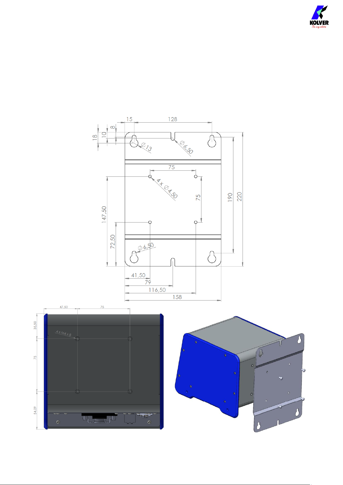
Installation of KDU unit.................................................................................................................7
Connectors .......................................................................................................................................8
Installation of KDS screwdriver....................................................................................................9
Installation of reaction arm......................................................................................................10
QUICK START...................................................................................................................................13
TERMINOLOGY ...............................................................................................................................16
OPERATING THE KDS SCREWDRIVER .....................................................................................18
OPERATING THE K-DUCER CONTROL UNIT.........................................................................20
Main Screen – Program Mode.....................................................................................................20
Main Screen – Program Mode – navigation tree ......................................................................22
Main Screen – Sequence Mode....................................................................................................23
Main Screen – Sequence Mode – navigation tree .....................................................................25
Retrieving and storing the screwdriving results......................................................................26
Connecting a barcode scanner ....................................................................................................28
Connecting Kolver accessories SWBX88, CBS880 ....................................................................28
CONFIGURING THE K-DUCER ...................................................................................................30
MAIN MENU ................................................................................................................................30
PROGRAMS menu .......................................................................................................................31
PROGRAMS menu tree............................................................................................................32
TORQUE & ANGLE menu ......................................................................................................35
RAMP & TIME menu ...............................................................................................................37
REV & PRE-REV menu ............................................................................................................39
OTHER menu ............................................................................................................................40
SEQUENCE SETTINGS menu ....................................................................................................43
SEQUENCE SETTINGS menu tree.........................................................................................44
CURRENT SEQ. menu .............................................................................................................45
GENERAL SETTINGS menu.......................................................................................................47
USB menu.......................................................................................................................................51
USB menu tree...........................................................................................................................53

Vers. 062721 4
K-EXPAND software ....................................................................................................................54
Interface Selection .....................................................................................................................54
Screwdriver................................................................................................................................55
Settings .......................................................................................................................................55
General Settings.........................................................................................................................56
Sequence Settings......................................................................................................................57
Programs ....................................................................................................................................58
Actions........................................................................................................................................60
REMOTE CONTROL INTERFACES..............................................................................................64
24V I/O............................................................................................................................................64
Introduction ...............................................................................................................................64
Pinout (CN3)..............................................................................................................................65
Wiring diagrams........................................................................................................................69
Binary tables for sequence and program selection ..............................................................71
MODBUS TCP ...............................................................................................................................73
Introduction ...............................................................................................................................73
Usage...........................................................................................................................................73
K-DUCER MODBUS map........................................................................................................74
MODBUS TCP code examples and literature .......................................................................75
OPEN PROTOCOL.......................................................................................................................76
Introduction ...............................................................................................................................76
Terminology...............................................................................................................................76
Supported MIDs........................................................................................................................76
MAINTENANCE AND CARE........................................................................................................78
INTRODUCTION .........................................................................................................................78
CALIBRATION..............................................................................................................................78
MAINTENANCE..........................................................................................................................79
EXPLODED VIEWS AND SPARE PARTS.....................................................................................80
GUARANTEE....................................................................................................................................82

Vers. 062721 5
INTRODUCTION
K-DUCER is the new class A intelligent transducerized assembly system from Kolver.
Thanks to a sophisticated control system, the electronic circuit communicates with KDS
series screwdriver equipped with integrated torque/angle transducer and allows to stop the
screwdriver instantly when reaching the preset torque or angle.
The AC 90÷260V - 50÷60Hz power supply is converted into 40VDC required by the KDS
series screwdrivers through a switching board.
IMPORTANT: K-DUCER is a highly accurate unit but it is critically important to select the
appropriate settings to ensure that the desired and proper torque is being applied and that
the screwdriver motor works efficiently. Read the menu description carefully and if unsure
please contact Kolver for support.
MODELS
K-DUCER power supply and control units are available in two versions:
Code
Model
Features
035001
KDU-1
035001/A
KDU-1A
as KDU-1 + RJ45 connector, provoding
Modbus TCP (server) communication
protocol and Open Protocol v1.6rev3
K-DUCER units are compatible with any of the KDS electric screwdrivers with transducer,
available in straight, pistol and fixture configuration.
Code
Model
Torque
(Nm)
Speed (rpm)
Min
Max
175015
KDS-MT1.5
0,1-1,5
50
850
175015/ESD
KDS-MT1.5/ESD
0,1-1,5
50
850
175016/ESD
KDS-MT1.5P
0,1-1,5
50
850
175016/U/ESD
KDS-MT1.5P/U
0,1-1,5
50
850
175115
KDS-MT1.5CA
0,1-1,5
50
850
175115/FN
KDS-MT1.5CA/FN
0,1-1,5
50
850
175015/A
KDS-MT1.5ANG
0,1-1,5
50
850
135006
KDS-PL6
0,5-6
50
850
135006/ESD
KDS-PL6
0,5-6
50
850

Vers. 062721 6
135007/ESD
KDS-PL6P
0,5-6
50
850
135007/U/ESD
KDS-PL6P/U
0,5-6
50
850
135106
KDS-PL6CA
0,5-6
50
850
135106/FN
KDS-PL6CA/FN
0,5-6
50
850
135006/A/ESD
KDS-PL6ANG
0,5-5,5
50
850
135010
KDS-PL10
0,8-10
50
600
135010/ESD
KDS-PL10
0,8-10
50
600
135011/ESD
KDS-PL10P
0,8-10
50
600
135011/U/ESD
KDS-PL10P/U
0,8-10
50
600
135110
KDS-PL10CA
0,8-10
50
600
135110/FN
KDS-PL10CA/FN
0,8-10
50
600
135010/A/ESD
KDS-PL10ANG
0,8-9
50
600
135015
KDS-PL15
0,5-15
50
320
135015/ESD
KDS-PL15
0,5-15
50
320
135016/ESD
KDS-PL15P
0,5-15
50
320
135016/U/ESD
KDS-PL15P/U
0,5-15
50
320
135115
KDS-PL15CA
0,5-15
50
320
135115/FN
KDS-PL15CA/FN
0,5-15
50
320
135015/A/ESD
KDS-PL15ANG
0,5-12
50
320
135020
KDS-PL20
2-20
10
210
135120
KDS-PL20CA
2-20
10
210
135120/FN
KDS-PL20CA/FN
2-20
10
210
135030/ANG
KDS-PL30ANG
3-30
10
140
135035
KDS-PL35
3-35
10
140
135135
KDS-PL35CA
3-35
10
140
135135/FN
KDS-PL35CA/FN
3-35
10
140
135045/ANG
KDS-PL45ANG
4-45
10
90
135050
KDS-PL50
5-50
10
90
135150
KDS-PL50CA
5-50
10
90
135150/FN
KDS-PL50CA/FN
5-50
10
90
135070/ANG
KDS-PL70ANG
7-70
10
50

Vers. 062721 7
INSTALLATION
Installation of KDU unit
The K-DUCER is supplied with the following mounting bracket (all dimensions reported in
mm):

Vers. 062721 8
The bracket should be fixed to the four provided 8mm depth female threads on the back
panel using the provided M4x8 screws.
Also available separately:
•table stand (part number 010400)
•vertically and horizontally adjustable bracket (part number 010401).
Connectors

Vers. 062721 9
TOOL connector
To connect a KDS series screwdriver. Take care to respect the alignment tabs on the
connector. See “Installation of KDS screwdriver” section for instructions on connecting the
screwdriver.
CN1 connector
Reserved for servicing the unit and upgrading the firmware.
CN2 male serial connector
To connect with a compatible barcode scanner, such as Kolver Barcode P/N 020050, serial
printers such as Kolver PRNTR1, or serial terminals (PC/PLCs).
CN4 female serial connector
To connect with Kolver accessories SWBX88/CBX880, serial printers such as Kolver
PRNTR1, or serial terminals (PC/PLCs).
CN3 I/O connector
To connect with 24V I/O functionality such as PLCs, pedals/buttons, LEDS, etc. Refer to
REMOTE CONTROL INTERFACES chapter.
CN5 ethernet connector RJ45
To connect using MODBUS TCP, Open Protocol, or K-Expand on any compatible device or
software (PLCs, PCs, etc). Refer to REMOTE CONTROL INTERFACES chapter.
USB mini B
To connect using K-Expand software. Refer to K-EXPAND software chapter.
USB A
Plug in a FAT32 formatted flash drive to automatically save screwdriving results and backup
all settings. Refer to the “Retrieving and storing the screwdriving results” and “USB menu”
sections.
Installation of KDS screwdriver
Cable connection and part numbers
The KDS screwdriver series require one of the following cables:
-2.5m male/female cable (code 250064)
-2.5m male/female cable with strain relief (code 250064/H)
-5.0m male/female cable (code 250564)
-5.0m male/female cable with strain relief (code 250564/H)

Vers. 062721 10
To connect the screwdriver to the unit:
1. insert the male connector into the appropriate TOOL connector on the bottom of the
unit, taking care to respect the alignment tabs. Push the connector into its position
and turn the OPEN/CLOSE nut clockwise until it clicks*
2. insert the female connector into the appropriate connector at the top of the
screwdriver, taking care to respect the alignment tabs. Push the connector into its
position and turn the OPEN/CLOSE nut clockwise until it clicks*
To disconnect the cable:
1. push the connector in lightly towards the screwdriver or the unit
2. turn the OPEN/CLOSE nut counterclockwise*
3. pull the connector out
*note: some models use a threaded nut instead of an OPEN/CLOSE nut. In this case, tighten
the nut all the way until it stops, without overtightening with excessive force.
Installation of reaction arm
Note: a reaction arm is ALWAYS required for KDS screwdrivers size 20Nm and above.
Kolver recommends always using a reaction arm for operator comfort, especially for
applications with torques above 5 Nm.
Fix the reaction arm to the indicated areas only.
KDS series screwdrivers sizes 15Nm and below have two positions designed for connecting
to the reaction arm:
1. The naked metal cylinder near the head of the screwdriver
2. The reinforced plastic section at the very top of the screwdriver (not present on the
pistol-shaped version)

Vers. 062721 11
KDS series screwdrivers sizes 20Nm and above have only one position designed for
connecting to the reaction arm:
1. The naked metal cylinder near the head of the screwdriver
KDS series screwdrivers sizes 20Nm and above also provide four threaded M4 holes for
fixing to a custom assembly.
Warning: do not connect the reaction arm anywhere other than the above designated areas.
Fixing the reaction arm to the middle of the screwdriver handle will squeeze the
screwdriver shell, causing damage to the internal components, and failing to absorb the
torque reaction safely and reliably.
Reaction arm connection for KDS series screwdrivers 15Nm and below:

Vers. 062721 12
CA automation versions:
Reaction arm connection for KDS series screwdrivers 20Nm and above:
CA automation versions:

Vers. 062721 13
QUICK START
Turn the unit on through the on/off switch on the lower panel. The unit will carry a general
system check and the words “NO SCREWDRIVER CONNECTED” will appear if no
screwdriver is connected.
You can still enter the main menu without any screwdriver connected.
When a screwdriver is connected, it will be recognized by the unit and the "CONNECTED
SCREWDRIVER" screen will appear for a few seconds, also showing the model and serial
number.
All information pertaining to the connected screwdriver can also be retrieved in the General
Settings menu.

Vers. 062721 14
If the parameters set in the current program are outside the allowable range of the
connected screwdriver, the following screen will appear:
To resolve the error, select a program previously configured for the connected screwdriver
model, or enter the main menu to modify the parameter out of range for the current
program.
The “Program parameter error” messages can be the following:
TorqueTargOverMax
Target torque higher than the allowed limit for the
screwdriver.
SpeedTargOverMax
Target speed higher than the limit allowed for the
screwdriver.
SpeedTargUnderMin
Target speed less than the limit allowed for the
screwdriver.
DownshiftTorqueOverTarg
The fast phase torque setting is higher than the final target
torque.
DownshiftSpeedOverMax
The speed of the slow phase of this program is higher than
the maximum allowed by the screwdriver.
DownshiftSpeedUnderMin
The speed of the slow phase of this program is less than the
minimum allowed by the screwdriver.
TorqueMaxOverMaxLim
In angle control: the maximum torque set in the program is
above the limit of the screwdriver.
In torque control: the maximum torque set in the program
is higher than 20Nm.
TorqueMaxUnderMinLim
In angle control: the maximum torque set in the program is
equal or lower than the minimum limit of the screwdriver.
In torque control: The maximum torque set in the program
is equal or lower than the target torque already set.

Vers. 062721 15
TorqueMinOverMaxLim
In angle control: the minimum torque set in the program is
equal or higher than the maximum torque already set.
In torque control: the minimum torque set in the program
is equal or higher than the target torque already set.
RevTorqueOverMax
The reverse torque of this program is higher than the
maximum torque of the screwdriver.
RevSpeedOverMax
The reverse speed is higher than the maximum allowed by
the screwdriver.
RevSpeedUnderMin
The reverse speed is lower than the minimum allowed by
the screwdriver.
If the connection with the screwdriver is successful, the main screen will be displayed and
the screwdriver will be ready for work.
Connect a thumb drive on the USB-A port (the larger USB port) to automatically save all
screwdriving results on a text file.

Vers. 062721 16
TERMINOLOGY
KDU/K-DUCER/control unit: the KDU1 / KDU1A control unit
KDS/screwdriver: the transducerized screwdriving tool to be used with the KDU control
unit
Transducer: electronic component installed inside the KDS screwdriver which measures
the torque in real time
Rundown/tightening: the screwdriving cycle, from start (pressing of the lever or initiating
remote lever control), to finish (automatic motor stop or lever or remote lever control
release, whichever happens first)
Torque: rotational force
Closing torque: the last torque value measured when the screwdriver motor stopped or
when the screwdriver lever or remote lever control was released
Target torque: the closing torque that the screwdriver system will apply in the rundown
(torque control mode only), resulting in a “Screw OK” result if successful
Prevailing torque: an optional phase of the rundown during which the applied torque is
allowed to exceed the target/closing torque
Torque control mode: a rundown where the screwdriver motor automatically stops upon
reaching the target torque
Angle: the revolutions of the tip of the screwdriver, in degrees. The start time of the angle
measurement depends on the settings chosen.
Target angle: the angle measurement upon which the screwdriver motor will stop (angle
control mode only), resulting in an “Angle OK” result if successful
Angle control mode: a rundown where the screwdriver motor automatically stops upon
reaching the target angle
Run time: the duration of the rundown, in seconds
Run time mode: a rundown where the screwdriver motor automatically stops at the
desired run time

Vers. 062721 17
Program/batch: a set of one or more screws sharing the same parameters (torque, angle,
speed, barcode, etc)
Program number: the identifier of one of the 64 configurable programs (1 to 64)
Current program: the program currently selected for rundowns
Program mode: in this mode, the unit works according the selected program
Sequence/Job: an ordered set of up to 16 programs, with the option to define how to
transition between programs
Sequence letter/number: the identifier of one of the 8 configurable sequences (A to H)
Current sequence: the sequence currently selected for rundowns
Sequence mode: in this mode, the unit works according to the selected sequence
OK/NOK: the result of the rundown. OK: rundown finished respecting all of the configured
parameters. NOK: rundown finished without respecting one or more of the configured
parameters.

Vers. 062721 18
OPERATING THE KDS SCREWDRIVER
(1) Lever
Press and hold the lever to initiate a rundown.
Warning: Kolver strongly recommends using a reaction arms when applying torques
greater than 5 Nm. A reaction arm with higher Nm capacity is required for KDS
screwdriver sizes 20Nm and above. Using KDS screwdrivers sizes 20Nm and above
without a reaction arm or with an improperly sized reaction arm may result in severe
injury or death.
The screwdriver will automatically stop according to the configured program, in either
an OK or a NOK state, depending on the success of the rundown.
The screwdriver will also stop if the lever is released in the middle of the rundown, and
either return to the READY state or raise the NOK state if the LEVER ERROR option is
active for the current program (Programs menu > Other > LEVER ERROR).
Note: KDS series screwdrivers sizes 20Nm and above provide a “START” button instead
of a lever. The functionality remains the same.

Vers. 062721 19
(2) Reverse button
Press and hold the button to initiate a defix run, rotating in the opposite direction of the
selected direction of rotation for the lever (see Programs menu > Other > ROTATION ).
The behavior of the reverse button can be changed from the general settings menu
(General Settings > REVERSE BUTTON).
(3) LEDs
The two LEDs indicate the state of the screwdriver:
•
Blinking white: the screwdriver was just connected to the K-DUCER control unit
•
Off: the screwdriver is ready, or the screwdriver is not connected
•
Solid green: the last screw result was OK
•
Solid red: the last screw result was NOK
•
Solid blue: screwdriver is running in the tightening direction, either via the lever or
via remote control
•
Solid purple: the screwdriver is running in the de-fix direction, either via the
reverse button, or via remote control
•
Blinking purple: the reverse button is in switch mode and is activated. The
screwdriver is ready to run in de-fix rotation via the main lever.
(4) Reaction arm connections
Fix the reaction arm to one these areas only, and never anywhere else on the
screwdriver.
Note: KDS series screwdrivers sizes 20Nm and above only provide the lower reaction
arm connection area.
(5) Hanging hook
To hang the screwdriver somewhere easily accessible in the operator’s workbench.
(6) Female connector
To connect the screwdriver to the K-DUCER control unit

Vers. 062721 20
OPERATING THE K-DUCER CONTROL UNIT
Main Screen – Program Mode
(1) Program (“PR”) number currently selected
Touch to select a different program (1 through 64).
(2) Screw count
Counter: screws successfully completed / number of screws in current program
Note: does not appear if NUMBER OF SCREWS parameter is set to zero. Number of
screws is also referred to as “batch size” in the industry.
(3) Main Menu Button (≡)
Tap to enter the main menu
(4) Angle value
Measured angle value for last screw, in degrees.
(5) Angle target
Shows the target angle when in angle control mode, or the min/max angle bounds when
in torque control mode or timed rundown mode, for the current program, in degrees.
(6) Menu lock status
White background means no password is required to access the configuration menu.
Red background means the configuration menu is password protected.
(7) Reset (“RST”) button
Screw/Program/Sequence Reset (“RST”) button. Presence and function of this button
depend on the corresponding settings in the GENERAL SETTINGS menu.
This manual suits for next models
2
Table of contents
Other Kolver Laboratory Equipment manuals
Popular Laboratory Equipment manuals by other brands

3M
3M Petrifilm 6408 Product instructions

Linkam Scientific Instruments
Linkam Scientific Instruments LTS420 user guide

Pasco Scientific
Pasco Scientific OS-8523 Instruction manual and experiment guide

RR Mechatronics
RR Mechatronics Interrliner XN1 FRL Instructions for use

Huvitz
Huvitz HLM-9000 user manual

Bruker
Bruker RS Service manual