Kolver MINI K Service manual

Vers. 140323 rev
TORQUE TESTER
MINI K
OPERATOR’S HANDBOOK
KOLVER S.r.l - Via Corner, 19/21 - 36016 THIENE - ITALY - tel. +39 0445 371068 fax +39 0445 371069
kolver@kolver.it - www.kolver.it

Vers. 140323 rev
1. APPLICATIONS
Recommended for all static and dynamic calibration of electric and pneumatic screwdrivers,
wrenches and power tools.
2. FEATURES
Model
Code
Torque
Range Nm
Accuracy
Transducer
MINI K1/S
021402/S
0,1 –1
± 1 cNm
Built-in
MINI K5/S
021403/S
0,3 –5
± 2 cNm
Built-in
MINI K20/S
021404/S
0,5 –20
± 3 cNm
Built-in
MINI KEF1
021405/F1
0,1 –1
± 1 cNm
MINI KE + KT1
MINI KEF5
021405/F5
0,3 –5
± 2 cNm
MINI KE + KT5
MINI KEF20
021405/F20
0,5 –20
± 3 cNm
MINI KE + KT20
MINI KEF50
021405/F50
2 –50
±10 cNm
MINI KE + KT50
MINI KEF100
021405/F100
5 –100
±10 cNm
MINI KE + KT100
MINI KE/5/S
021405/5/S
0,5 –5
± 3 cNm
MINI KE + KTE5
MINI KE/25/S
021405/25/S
2 –25
±10 cNm
MINI KE + KTE25
MINI KE/50/S
021405/50/S
5 –50
± 10 cNm
MINI KE + KTE50
MINI KE/100/S
021405/100/S
10 –100
± 20 cNm
MINI KE + KTE100
▪Built-in transducer to measure on joint simulator (MINI K.../S)
▪External transducer to measure on joint simulator (MINI KEF…)
▪External rotary transducer to measure the real torque being applied from the tool (MINI KE/…/S)
▪Three units of torque measurements: Nm, Kgf.cm, lbf.in.
▪Manual and auto reset functions to clear displayed values
▪Battery powered (9V)
▪AC adapter cord (12V, 500mA, 6W, external +, cylindrical jack, hole 2,5 mm and 5,5mm external)
▪Correction factor (FATC): to connect more ext. transducers on the same tester
▪Mini USB to connect to PC and to communicate to Torque Analyzer
▪Certificate of calibration
▪Automatic shut down

Vers. 140323 rev
3. DESCRIPTION
1. Mounting holes
2. Display 4 digit / 8 lines
3. “ON/OFF” key : press for 3 seconds to switch tester on or off
4. “CLEAR” key : press to reset the displayed value
5. “UNIT” key : press to select the unit of torque measurements
6. Internal transducer or port for external transducer
4. MOUNTING
It is strongly recommended securing the tester through slots “1” to a workbench before operating.
Immobilizing the tester when checking torque values over 1 Nm is critical for the safety the operator as well
as for the accuracy of torque measurements during operation.

Vers. 140323 rev
5. JOINT SIMULATORS
The Joint Simulator (JS) consists of a screw compressing a series of washers enclosed in a case with hex
female head for proper fit to any Kolver torque tester. The head of the joint simulator can be supplied with
different attachment depending on the model used which allows the screwdriver to be connected to the joint
simulator.
Since a joint simulator cannot duplicate actual joints, the torque values displayed on the minik may vary
from the actual torque that a screwdriver will apply to the actual assembly.
Minik1 is supplied with a built-in joint simulator to increase low torque measurements accuracy.
Joint simulators available:
Code
Model
Screwdriver side
attachment
Torque tester side
attachment
Compatibile
torque tester
model
Included
with
240620
Hex13/M1,6
M1,6 Female thread
Female hex 13mm
MiniK1
K1
MINIKEF1
on request
240621
Hex13/M2
M2 Female thread
240622
Hex13/M3
M3 Female thread
240640
Hex13 –1/4“
M4
Male hex 1/4“
Female hex 13mm
MiniK1
K1
MINIKEF1
MINIKEF1
240600
Hex13 –1/4“
M6
Male hex 1/4“
Female hex 13mm
MiniK5
MINIKEF5
K5
MiniK5
MINIKEF5
K5
240800
Hex13 –1/4“
M8
Male hex 1/4“
Female hex 13mm
Mini K20
MINIKEF20
K20
Mini K20
MINIKEF20
K20
240901
3/8” M12
Female Sq 3/8”
Male Sq 3/8”
MINIKEF50
MINIKEF50
240902
1/2”M12
Female Sq 1/2”
Male Sq 1/2”
MINIKEF100
MINIKEF100

Vers. 140323 rev
NB. We recommend to grease the JS each 1000 cycles.
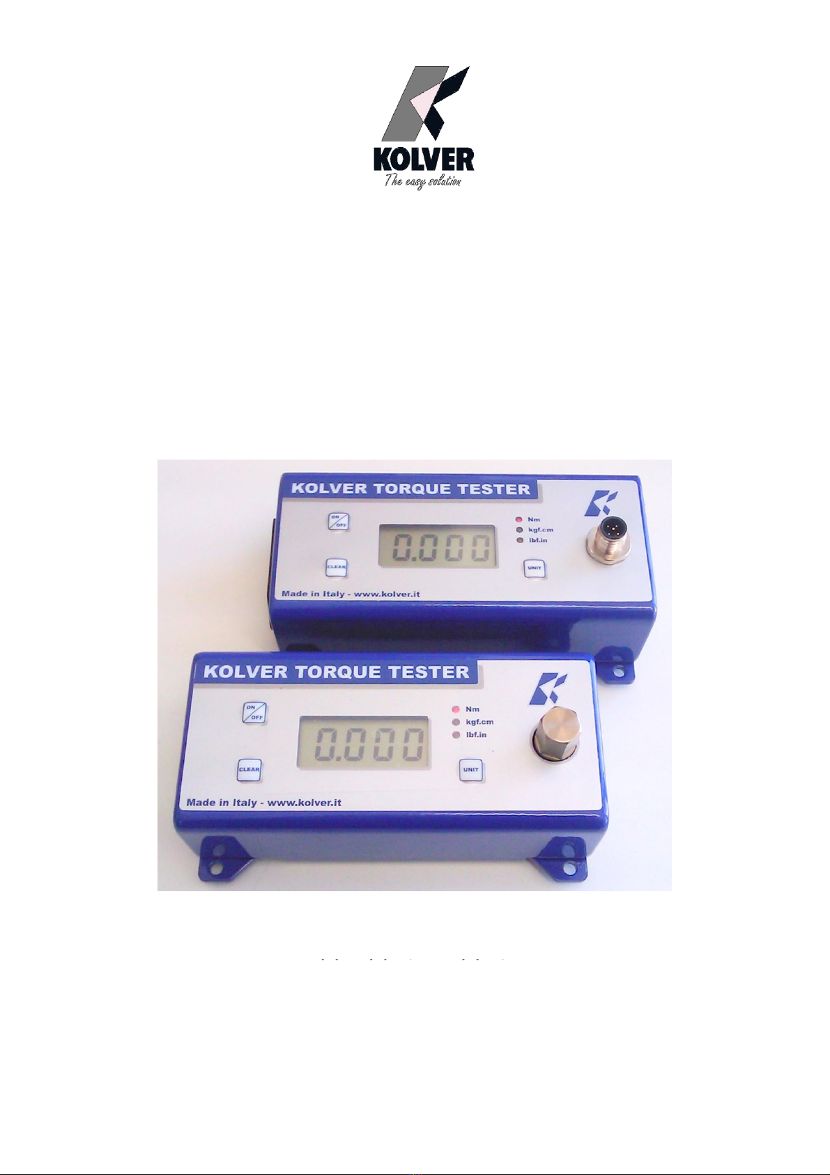
6. STARTING AND OPERATING THE TESTER
1. Immobilize the tester when checking torque values over 1 Nm. This is critical for the safety the operator as
well as for the accuracy of torque measurements during operation.
2. Switch the tester on pushing the ON/OFF key.
If used only with battery check its status. If the tester does not switch on or the display is not clear enough,
please replace the battery. When used it the AC adapter, this will disable the battery. The battery is not
rechargeable. The display will show the main screen:
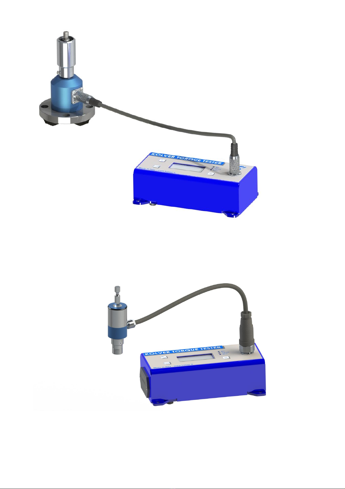
3. Insert the joint simulator into its 13mm hex seat and make sure the screw is in its upper position (if not run
the driver anticlockwise to unscrew it). The tester is ready for a measuring cycle.
In minik1, only unscrew before measuring.
4. Run the joint simulator screw all the way down until it stops and read the torque value on the display. Run
the screw up to be ready for the next cycle.
5. Press the “ON/ESC” key for 3 seconds to switch the tester off. The tester features a built-in auto shut off
mode function to save power when not in use. If there is no activity for 3 minutes, such as key press or no
torque input, the tester will shut down. To restore power press the “ON/ESC” key for 3 seconds
NB. Before starting, always check that the screen displays 0.000. Instead push CLEAR.
7. SELECTING THE UNIT
MEASURING UNIT: Nm, kgf.cm and lbf.in
To change unit: press Unit key until the desired unit has been selected.
Each unit is indicated by a LED of different color: red for Nm, green for kgf.cm and yellow for lbf.in.
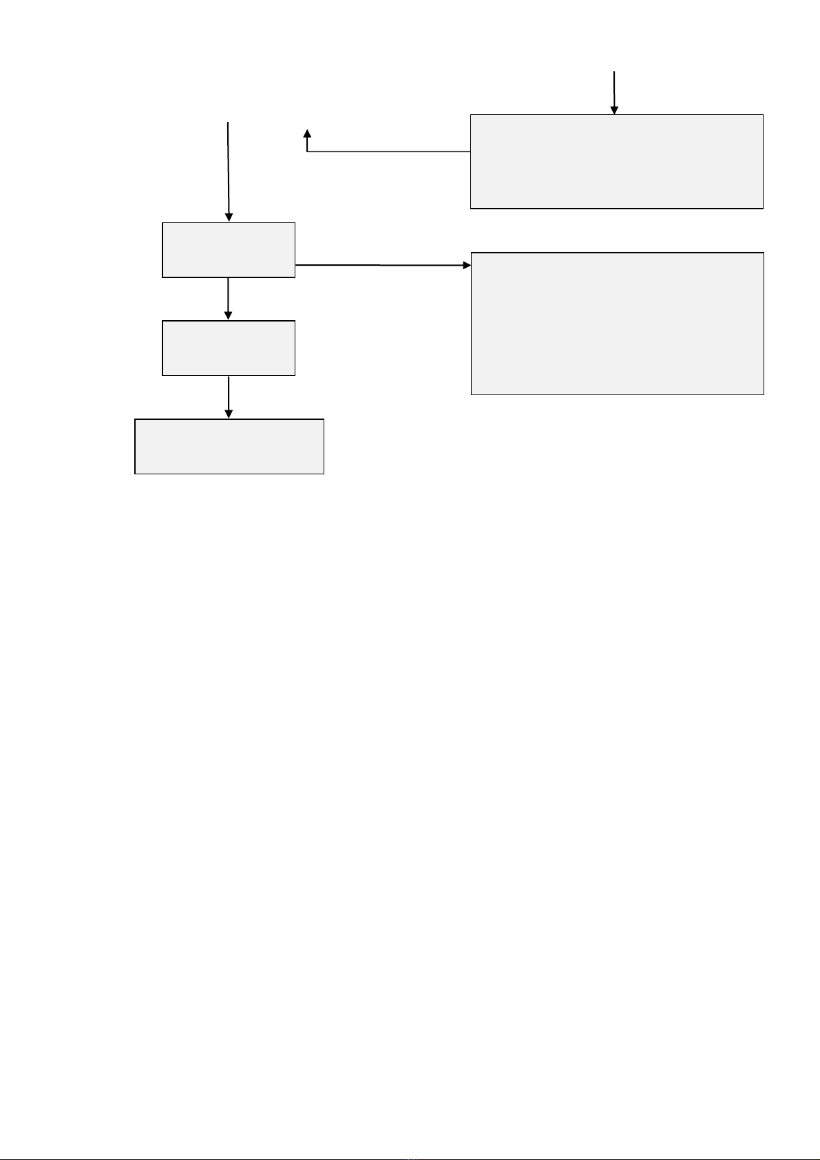
8. SELECTING MANUAL OR AUTO RESET
The flow chart below shows how to select Manual or Auto Reset.
Sens, Cal and Fatc functions (sensitivity, calibration and correction factor) can be modified only by
authorized personnel.
When you select Manual Reset “Coff”: you need to push “CLEAR” to remove readings from the display
and reset all values to zero.
When you select Auto reset “Con”: any new measure will replace the previous one without resetting the
value to zero.

Vers. 140323 rev
Push ON/OFF
Push at the same time
CLEAR+UNIT for 5 sec.
See
“Prg”
After 3 sec. see
“SEnS”
See
“rST”
Push UNIT
See
“CAL”
In case of calibration first
set the weights, then push
ON/OFF
Push UNIT
Push “UNIT” per scorrere la lista.
-TRACK: Track Mode active.
-OFF : Automatic reset off.
-ON : Automatic reset on .
Push “ON/OFF”to save or “CLEAR” to
exit
Push ON/OFF
Automatic detection of FATC.
Once finished, remove the weight and push
“ON/OFF” to save or “UNIT” to go to
Manual Mode to improve the calibration.

Vers. 140323 rev
Push UNIT
Push ON/OFF
ON/OFF
9. EXTERNAL TRANSDUCER for miniKe
The MINI KEF and MINI KE/S torque testers consist of a MINI KE torque reader and an external static or
rotary transducer. The static transducer combined with a joint simulator allows you to check the torque
measured by the screwdriver and calibrate it according to your needs. The rotary transducer is the ideal tool
for verifying the real torque applied by the screwdriver directly on the screw (and not on a joint simulator).
Thanks to the modification of the FATC (correction factor) and the SENS (full scale value of the connected
transducer), it is possible to calibrate several external transducers in a single MINI KE reader (see
Programming Menu).
Rotary and non rotary transducers for lower or higher torque ranges available on request.
The minike can read torque up to 500 Nm.
MINI KE READER
Push UNIT
See
“DATE”
See
“FATC”
Push UNIT
Push UNIT
Return to the main
screen
Push ON/OFF
Set date and hour:
Push “UNIT” to set hour.min
(24hours, day.month.year.
At each digit push “ON/OFF” to save or
“CLEAR” to exit.
Push ON/OFF
MANUAL Mode:
Push on “UNIT” and “CLEAR” to modify
the FATC.
Remove the weight and push “ON/OFF” to
save.

Vers. 140323 rev
Example of MINI KE + KT series external cell + joint simulator

Vers. 140323 rev
Example of MINI KE + KTE series external cell + joint simulator

Vers. 140323 rev
KT SERIES TRANSDUCERS
Code
Model
Torque range
Attachment
023001
KT1
0,05-1
Female hex 13mm
023005
KT5
0,3-5
Female hex 13mm
023020
KT20
0,5-20
Female hex 13mm
023050
KT50
2-50
Female Sq 3/8”
023100
KT100
5-100
Female Sq 1/2”
KT1 –KT5 –KT20

Vers. 140323 rev
KT50

Vers. 140323 rev
KT100

Vers. 140323 rev

Vers. 140323 rev
ROTARY TRANSDUCERS
Code
Model
Torque range
Attachment
022405
KTE5
0,5-5
Maschio-femmina esagonale 1 / 4 “
022425
KTE25
2-25
Maschio-femmina esagonale 1 / 4 “
022450
KTE50
5-50
Maschio-femmina quadro 3 / 8 “
022411
KTE100
10-100
Maschio-femmina quadro 1 / 2 “
KTE5-KTE25 MODELS

Vers. 140323 rev
KTE50 MODEL
KTE10 MODEL

Vers. 140323 rev
10. MAINTENANCE
The minike testers are maintenance free. The electronics and the internal transducers have no wearing parts
except the battery once its charge is over. The internal transducer should be calibrated every 12 to 30 months,
depending on the frequency of use.
WARNING: The overload protection of the internal transducer is limited to 125% of nominal value. Damages
due to overloading will result in inaccurate readings and will not be covered by our warranty.
IMPORTANT: the calibration certificate has a maximum validity of 36 months (ref. DIN 51309, ISO 10127-
2). The instrument must be calibrated again (regardless of the date of last calibration):
-if it has been overloaded
-after any corrective maintenance (eg: upgrade with new software)
-after improper use (eg: tested with impact wrench or jacks)
-in case of doubt about the measurement results.
11. WARRANTY
1. This KOLVER product is guaranteed against defective workmanship or materials, for a maximum
period of 12 months following the date of purchase from KOLVER, provided that its usage is limited
to single shift operation throughout that period. If the usage rate exceeds of single shift operation, the
guarantee period shall be reduced on a prorata basis.
2. If, during the guarantee period, the product appears to be defective in workmanship or materials, it
should be returned to KOLVER or its distributors, transport prepaied, together with a short
description of the alleged defect. KOLVER shall, at its sole discretion, arrange to repair or replace
free of charge such items.
3. This guarantee does not cover repair or replacement required as a consequence of products which
have been abused, misused or modified, or which have been repaired using not original KOLVER
spare parts or by not authorized service personnel.
4. KOLVER accepts no claim for labour or other expenditure made upon defective products.
5. Any direct, incidental or consequential damages whatsoever arising from any defect are expressly
excluded.
6. This guarantee replaces all other guarantees, or conditions, expressed or implied, regarding the
quality, the marketability or the fitness for any particular purpose.
7. No one, whether an agent, servant or employee of KOLVER, is authorized to add to or modify the
terms of this limited guarantee in any way. However it’s possible to extend the warranty with an
extra cost. Further information at kolver@kolver.it

Vers. 140323 rev
EXPLODED VIEWS AND PART LISTS
Minik1/S
REF
DESCRIPTION
CODE
1
Plastic support (4 pcs)
800016
2
Internal transducer 1Nm (miniK1)
240505
3
Washer M4 (7 pcs)
241015
4
Screw M4 x 20
241014
5
Flat washer M3 (4 pcs)
800042
6
Nut 6,3 mm (4 pcs)
241003
7
Metal housing miniK../S
240001/BCU
8
Membrane miniK
241008
9
Battery 9V not rechargeable
241010
10
Battery seat miniK
241005
11
Board miniK + display
241002/N
12
Screw M3 (5 pcs)
800056
13
Washer M3
800041
14
Base miniKe
240001/BF2
15
Screw M3 x 6 TSP (6 pcs)
801002
16
Screw M3 x 22
241012
17
Screw M4 x 8 (3 pcs)
241011
Bit - hex 1/4", L=50 mm, diam. 4 mm
FE-13040
Case
241000
Power supply 12V
241009/N

Vers. 140323 rev
minik5/S –minik20/S
REF
DESCRIPTION
CODE
1
Plastic support (4 pcs)
800016
2
Internal transducer 5Nm (miniK5/s)
240503
Internal transducer 20Nm (miniK20/s)
240504
3
Washer M3 (5 pcs)
800041
4
Flat washer M3 (4 pcs)
800042
5
Nut 6,3 mm (4 pcs)
241003
6
Metal housing miniK../S
240001/BCU
7
Membrane miniK
241008
8
Battery 9V not rechargeable
241010
9
Battery seat miniK
241005
10
Board miniK + display
241002/N
11
Screw M3 (5 pcs)
800056
12
Base miniKe
240001/BF2
13
Screw M3 x 6 TSP (6 pcs)
801002
14
Screw M3 x 22
241012
15
Screw M4 x 8 (3 pcs)
241011
Joint simulator M6 (miniK5)
240600
Joint simulator M8 (miniK20)
240800

Vers. 140323 rev
Case
241000
Power supply 12V
241009/N
Minike/xx/S
REF
DESCRIPTION
CODE
1
Plastic support (4 pcs)
800016
2
Washer M3 (3 pcs)
800041
3
Flat washer M3 (4 pcs)
800042
4
Nut 6,3 mm (4 pcs)
241003
5
Metal housing miniK../S
240001/BCU
6
Membrane miniK
241008
7
Connector M 5 pin
231666
8
Battery 9V not rechargeable
241010
9
Battery seat miniK
241005
10
Board miniK + display
241002/N
11
Screw M3 (5 pcs)
800056
12
Base miniKe
240001/BF2
13
Screw M3 x 6 TSP (6 pcs)
801002

Vers. 140323 rev
14
Screw M3 x 22
241012
15
Screw M4 x 8 (3 pcs)
241011
Case
241000
Power supply 12V
241009/N
M6 (code 240600)
Pos.
Description
Code
01
Seiger
240601
02
Joint shaft
240602
03
Washer spring (8)
240603
04
Joint housing
240604
05
Screw M3x5
872443/ZN
This manual suits for next models
24
Table of contents
Other Kolver Laboratory Equipment manuals
Popular Laboratory Equipment manuals by other brands

TeleDart
TeleDart RD206 quick start guide

Thermo Scientific
Thermo Scientific Nunc Cell Factory CF1 Instructions for use

Bioreba
Bioreba HOMEX XS user guide

Civco
Civco Astra VR installation manual

Tianlong
Tianlong Real-time PCR System user manual

Thermo Scientific
Thermo Scientific Sorvall WX100 Plus instruction manual

Dynamica
Dynamica VELOCITY 14 Pro instruction manual

Revolutionary Science
Revolutionary Science Saniclave RS-SC-102 instruction manual

PAXXO
PAXXO PACTOSAFE 4.0 manual

CEFLA
CEFLA MOCOM Supreme-17 manual

NuAire
NuAire LabGard NU-581-400 Operation and maintenance manual

Dionex
Dionex UltiMate 3000 Series operating instructions