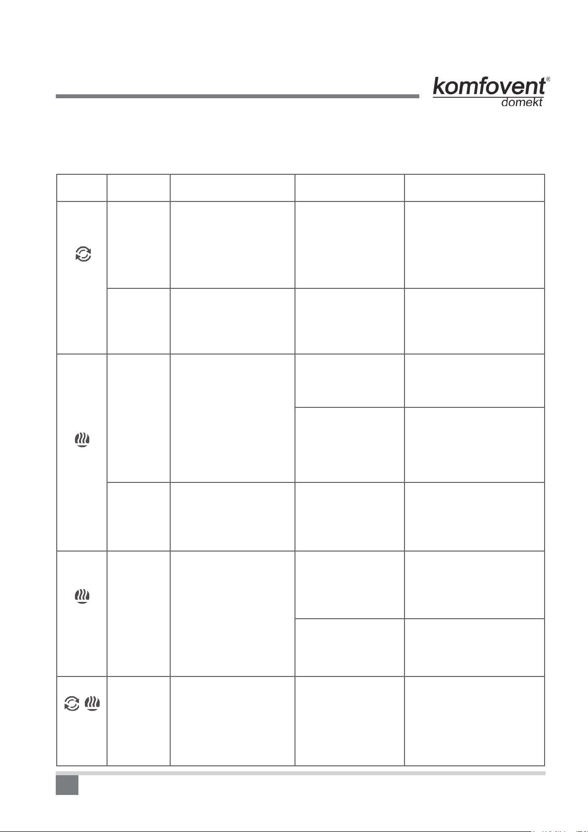
Komfovent DOMEKT User manual

EN
DOMEKT
Series Air Handling Units with C4 Controller
Electrical Installation and Operation Manual

2
Table of Contents
1. INSTALLATION MANUAL .....................3
1.1. Electric Power Supply Connection .....................3
1.2. Control Panel Installation .....................3
1.3. Kitchen Hood Installation .....................4
1.4. Control Contacts Connection .....................5
2. OPERATION MANUAL .....................5
2.1. Unit Control .....................5
2.2. Control Panel Indications .....................5
2.3. Ventilation Intensity Setting .....................6
2.4. Temperature Setting .....................7
2.5. “Winter / Summer” Mode .....................7
2.6. OVR function .....................7
2.7. Activation of the “OVR” Function .....................8
2.8.CongurationOfAutomationFunctions .....................8
2.9. Troubleshooting .....................9
Unit Functional Diagram ................... 11
Wiring Diagram ...................12

3
1. INSTALLATION MANUAL
Installationworkscanbeperformedonlybythespecialiststhathaverequiredqualication.Duringinstallation
followingrequirementsmustbefullled.
It is recommended to lay control cables separately from power cables in a distance
no less than 20 cm.
1.1. Electric Power Supply Connection
Air handling unit voltage is 230V AC; 50 Hz , therefore it is necessary to install the socket with grounding of
corresponding capacity (see wiring diagram). Electric power supply cable type is indicated in electric diagram.
Unit must be connected to the stationary installation by solid cable through 10A
circuit breaker with maximum 30mA current leakage relay.
Before connecting unit to the electrical power supply, it is necessary to check
whether earthing has been installed properly in conformance with electric safety
requirements.
1.2. Control Panel Installation
1. Control panel must be installed in the room under given following conditions:
•ambienttemperature00C ... 400C;
•relativehumiditylimits20%...80%;
•protectionmustbeensuredfromaccidentallyverticallyfallingwaterdrops(IPX2).
2. Installation height must be not less than 0,6m from the ground.
3. Control panel connection is projected through the hole in its backside (see 1.2 Picture).
4.Controlpanelisxedafterscrewingtwoholesonthefasteningsurface.
1.2 Picture
Control Panel Connection
The length of cable connecting control panel and air handing unit can not exceed
20 m. Electric power supply cable type is indicated in wiring diagram.
Installation Manual

4
Installation Manual
1.3. Kitchen Hood Connection
Air handling units KOMFOVENT DOMEKT REGO 200VE have possibility of kitchen hood connection (in the
functionaldiagramitismarkedbyKH).Aftershingthecablethroughtherubbergasket,(locatedinthewall)it
has to be connected to connection box J11.(see 1.3 Picture).
Connector connection is performed strictly according to numeration given in wir-
ing diagram, or adequate markings (see wiring diagram).
When disconnecting unit sections, do not pull by connecting wires and cables!
Before starting any operations inside the unit, make sure that the unit is switched
off and the power supply voltage is shut off.
1.3 Picture
Kitchen Hood Connection
1.4. Control Contacts Connection
Air handling units with the C4 controller have the connection of additional device (switch, sensor, timer, button etc).
For this function external cable is brought out from the unit (see 1.4 Picture). Detailed description of connection pos-
sibilities is provided in chapter 2.6.
1.4 Picture
Connection of additional control device

5
2. OPERATION MANUAL
2.1. Unit Control
The control panel (see 2.1 Picture) can be installed in any user-friendly place and is intended for remote control
of air handling unit. Control panel light diodes indicate unit operation modes. Ventilation intensity, operation modes
and are set by the switches.
2.1 Picture
C4 Control Panel View
1. Heat exchanger operation / failure indication diode
2. Electrical air heater operation / failure indication diode
3. “Summer / Winter“ mode setting switch
4. Ventilation intensity selection switch
2.2. Control Panel Indications
Indication Symbol Light Indication Description
Shines Heat recovery
Blinks Heat recovery failure
Shines Air heater is operating
Blinks 3 times per second Heating function failure
Blinks 8 times per second Temperature sensor failure
Blinks successively every second Unit maintenance inspection must be carried out
More detailed description of failures and and their elimination is provided in
chapter 2.9.
12
3
4
+
Operation Manual

6
Operation Manual
2.3. Ventilation Intensity Setting
Air handling unit has three ventilation intensity levels, which are adjusted by switch (4) on the panel:
– minimum; – normal; – maximum.
Normal (second) ventilation intensity level for supply air , and for exhaust air fans can be adjusted
accordingtoparticularventilationsystemproject.OnestepbackorforwardforACfansandgraduallyfrom20to100%
for EC fans. Desirable ventilation level is set using potentiometers located on the wall of automatic box inside the unit.
2.3 Picture
Fans speed selection potentiometers
Inthetablebelowpossiblepotentiometerscongurationispresented,accordingtodifferenttypesoffans:
Setting
AC fan EC fan
Marking Voltage, V Intensity,%
hIII 170 max. 100
Factory setting II 150 60
iI 120 min. 20

7
Operation Manual
2.4. Temperature Setting
Desirable supply air temperature is set with screw on potentiometer located on the wall of automatic box inside
the unit:
2.4 Picture
Temperature setting potentiometer
2.5. “Winter / Summer” Mode
By control panel switch (3) unit operating mode is set:
– „Summer“: electrical heater operation is blocked;
– „Winter“: electrical heater operation is available.
Note: When outdoor temperature is near setpoint (15 ... 300C), to save electric energy “Summer” operating
mode should be selected.
2.6. “OVR” function
“OVR” (Override) function is intended for remote unit control by an additional external device. After the activa-
tion of this function the current mode of operation will be ignored and the unit will operate at a set intensity.
Applications of the “OVR” function:
•MaintenanceofCO2quantity in room – by adding an additional CO2sensor (with relay), the main user-set
ventilation rate at higher CO2will be switched to the maximum intensity until the room is ventilated, and then again
willreturntotheuser-denedintensity.
•Maintainingrelativehumidityintheroom–aftercontactingtheexternalrelativehumiditysensor(withrelay),
automatically switching to maximum or different set ventilation intensity the humidity level desired by the user will
be maintained.
•Ventilationondemand–whenthemotionsensorisconnectedtothecontrolcontacts,ventilationwillbead-
justed according to demand, i.e. if people are indoors, ventilation will be carried out according to the set “OVR“
intensity and if there‘s nobody in the room - the unit will operate according to the main user intensity, for example,
the minimum.
•Ventilationwithadditionalairextraction–connectionofadditionalextractingdevice,forexample,akitchen
hood or other extraction device without a separate fan, is intended, thus the air extraction is carried out by the
unit itself. After the activation of the function the supply and exhaust air fans start operating at maximum intensity.

8
Operation Manual
•Negativepressurecompensation–intendedforsystemswhereairextractioncanbecarriedoutinaseparate
air extraction fan. Thus, for the compensation of negative pressure in room, the “OVR” function can be activated
by separate control contacts. After the activation of the function the exhaust air fans start operating at maximum
intensity and the exhaust air fan goes off.
Note: To make this function work, namely to stop the exhaust air fan in the “OVR” mode, the jumper No 4 on
the automation box should be ON (2.8. Picture).
2.7. Activation of the “OVR” Function
The „OVR“ function can be activated in two ways:
1. With the external control device. Connection is described in chapter 1.4. After connecting (short-circuiting)
the FC contacts (see the wiring diagram), the unit will operate in the selected „OVR“ mode (see chapter 2.6.), and
after their disconnection the unit will return to the previous operating mode.
2. With the control panel. In this case there is no need for additional connections to external control devices,
the function is activated by the control panel, and the unit will operate in the selected „OVR“ mode until the unit
internal timer is active.
„OVR“ mode activation procedure:
• Enable the maximum level with the ventilation intensity selection switch (4) (Picture 2.1.) (before enabling,
the unit must operate at a minimum or at normal intensity).
• After enabling the maximum level, switch back and forth the “Summer / Winter“ mode setting switch (3) in
5 seconds as many times as the „OVR“ function timer has to be active:
1 time 2 times 3 times
Timer 30 min. Timer 60 min. Timer 90 min.
• After the timer activation, the required level of ventilation has to be set, in which the unit will operate after
the timer is shut down, i.e. when the set „OVR“ mode time will expire.
Example. „OVR“ mode activation for 1 hour:
2 times
123
Note: In order to disable the „OVR“ mode before the timer period expires, it is necessary to carry out the above
steps (1) and (3), and to omit the step (2).
2.8. Conguration Of Automation Functions
Switches (2.8. Picture) on the automatic box can be used for the selection of heat exchanger type, heater and
fan, and the “OVR” function mode. Settings take effect only after rebooting the power supply.

9
Operation Manual
Switch No. ON OFF
1 Rotary heat exchanger Plate heat exchanger
2 Water heater Electric heater
3 EC fans AC fans
4 “OVR” mode when the exhaust air fan is off Usual “OVR” mode
2.8 Picture
Automation conguration switches
2.9. Troubleshooting
If the unit is inoperative:
• Make sure the feeding cable is plugged into an electrical outlet.
• Check all safety fuses of the automatic control block. In case of need, replace the faulty fuses with the new
ones of the same electric parameters (fuses parameters are in wiring diagram).
If air ow is reduced:
• Check set ventilation intensity level (see chapter 2.3.).
• Checkairlters‘condition.Ifneeded,replacewiththenewones.
• Check supply/exhaust air diffusers adjustment.
• Check for clogging outside air intake grille.
• Check if system ducting is not damaged and there are no extraneous things inside.
If supplied air is too cold:
• Check temperature setting (see chapter 2.4.).
• Check if „Winter“ mode is set on the panel.
• Check if there is no failure indication on the control panel (see table 2.9.).
• Check fuse F2 located on the automatic box.
Whenunitisoperating,controlpanellightdiodescanashornot,butifatleast
one light diode blinks, it means that failure is indicated. Please refer to 2.9 table.
Before starting any operations inside the unit, make sure that the unit is switched
off and the power supply voltage is shut off.
Detailed description about unit maintenance inspection is provided in Installation and Maintenance Service
Manual.

10
Operation Manual
2.9 Table
Failures indicated on the control panel, possible reasons and it elimination
Failure
indication Unit type Protection tripping
description Possible failure cause Failure elimination
Blinks 3
times per
second
Unit with
rotary heat
exchanger
When there is no signal from
the rotor’s rotation sensor, if
the “Winter” season is set,
the unit will stop operating in
2 min. And if “Summer” sea-
son is set, unit will continue
operating.
The belt is broken, fai-
lure of the rotor motor
or rotor sensor.
Check rotor drive and rotation
sensor condition.
Unit with
plate heat
exchanger
If the freezing protection
of the heat exchanger is
activated and is not re-
stored in 10 min, the unit
will stop operating.
Temperature of the
air passing through
plate heat exchanger,
dropped lower allow-
able level.
Check by-pass damper con-
dition and actuator perfor-
mance. It is recommended to
decrease ventilation level.
Blinks 3
times per
second
Unit with
electric
heater
Unit with electric heater
has emergency protection
from overheating at 90°C
with automatic reset and at
120°C with manual reset.
Heater is disconnected
duetolowairow.
When heater cools down, pro-
tection restores automatically.
It is recommended to increase
ventilation intensity level.
Electric heater over-
heating protection is
on.
It is possible to restore emer-
gency overheating protection
with button “RESET” (located
on the heater), only if before
heater overheating cause has
beenclariedandeliminated.
Unit with
water heater
In the unit with water heat-
er, when the water tem-
perature falls below the
permitted value of +9°C,
the unit will stop operating.
Failure of the hot water
preparation and supply
function in the heating
system.
Check circulation pump and
heating system condition,
heating valve actuator per-
formance.
Blinks 8
times per
second
Independent
of unit type
If the supply air tempera-
ture is not of the permit-
ted values: +5°C …-+45°C,
unit will stop operating
with 10 min. delay. When
temperature exceeds the
maximum permitted lim-
its: -30°C...+75°C, the unit
stops operating immedi-
ately.
The supplied air is too
cold or too hot.
Check temperature and sea-
son settings. Check the heat
exchanger and heater opera-
tion.
Supply air temperature
sensor is not connected
or broken down.
It is necessary to check sensor
connections or change the sen-
sor.
+
Blinks
every
second
Independent
of unit type
Depending on the intensity
of unit operation, at a cer-
tain time a periodic inspec-
tion message appears on
the control panel.
---
After disconnecting the
unit from power supply, it
is necessary to carry out
periodic inspection of the unit,
i.e.tochecktheairlterclogging
and the condition of the heat ex-
changer, the heater and fans.

11
Functional Diagram DOMEKT REGO
Functional Diagram DOMEKT RECU
AB Control box RT Rotary heat exchanger
B1 Supply air temperature sensor T1 Heat exchanger safety sensor
D1 Rotor rotation sensor V1 Supply air fan
FC External forcing contacts connection V2 Exhaust air fan
FG1 By-pass damper actuator VP Control panel
HE1 Electric heater VK** Water heater
KH* Kitchen hood connection B2** Return water temperature sensor
M1 Motor of rotary heat exchanger TG1** Hot water mixing valve actuator
PF Airlter S1** Circulation pump
PR Plate heat exchanger VB** Water heater control box
* Intended for REGO 200VE air handling unit only.
** Intended only for units with water heater.
Unit Functional Diagram

12
Wiring Diagram
DOMEKT REGO 200VE/400VE/250PE/400PE Wiring Diagram
B1 Supply air temperature sensor TK1 Safety thermostat from overheating 90oC
D1 Rotor rotation sensor TK2 Thermostat from overheating 120oC with manual RESET
EK1 Electric heater 1kW TR1 Autotransformer 1A
F1 Fuse T 4A V1 Supply air fan
F2 Fuse F 6,3A V2 Exhaust air fan
FC External forcing contacts connection VB Control board
KH* Kitchen hood (* connection intended for REGO 200VE only) VP1 Control panel
M1 Motor of rotary heat exchanger VP2 Control panel with touch-sensitive buttons
RT Rotary heat exchanger
Colors marking:
R - red
Y - yellow
G - green
W - white
B - blue
N - brown
K - black
G/Y - green/yellow

13
DOMEKT REGO-200VW/400VW/250PW/400PW Wiring Diagram
B1 Supply air temperature sensor RT Rotary heat exchanger
D1 Rotor rotation sensor TR1 Autotransformer 1A
F1 Fuse T 4A V1 Supply air fan
F2 Fuse F 6,3A V2 Exhaust air fan
FC External forcing contacts connection VB Control board
KH* Kitchen hood (* connection intended for REGO 200VE only) VP1 Control panel
M1 Motor of rotary heat exchanger VP2 Control panel with touch-sensitive buttons
Colors marking:
R - red
Y - yellow
G - green
W - white
B - blue
N - brown
K - black
G/Y - green/yellow

14
DOMEKT REGO 200VE/400VE/250PE/400PE-EC/600HE-EC Wiring Diagram
Wiring Diagram
B1 Supply air temperature sensor RT Rotary heat exchanger
D1 Rotor rotation sensor TK1 Safety thermostat from overheating 90oC
EK1 Electric heater 1kW TK2 Thermostat from overheating 120oC with manual RESET
F1 Fuse T 4A V1 Supply air fan
F2 Fuse F 6,3A V2 Exhaust air fan
FC External forcing contacts connection VB Control board
KH* Kitchen hood (*connection intended for REGO 200VE only) VP1 Control panel
M1 Motor of rotary heat exchanger VP2 Control panel with touch-sensitive buttons
Colors marking:
R - red
Y - yellow
G - green
W - white
B - blue
N - brown
K - black
G/Y - green/yellow

15
DOMEKT REGO-200VW/400VW/250PW/400PW/600HW-EC Wiring Diagram
B1 Supply air temperature sensor RT Rotary heat exchanger
D1 Rotor rotation sensor V1 Supply air fan
F1 Fuse T 4A V2 Exhaust air fan
F2 Fuse F 6,3A VB Control board
FC External forcing contacts connection VP1 Control panel
KH* Kitchen hood (* connection intended for REGO 200VE only) VP2 Control panel with touch-sensitive buttons
M1 Motor of rotary heat exchanger
Colors marking:
R - red
Y - yellow
G - green
W - white
B - blue
N - brown
K - black
G/Y - green/yellow

16
Wiring Diagram
DOMEKT RECU 350VE/500PE Wiring Diagram
B1 Supply air temperature sensor TK2 Thermostat from overheating 120oC with manual RESET
T1 Thermostat 0oCTR1 Autotransformer 1A
EK1 Electric heater 1kW V1 Supply air fan
F1 Fuse T 4A V2 Exhaust air fan
F2 Fuse F 6,3A VB Control board
FC External forcing contacts connection VP1 Control panel
FG1 By-pass damper actuator VP2 Control panel with touch-sensitive buttons
TK1 Safety thermostat from overheating 90oC
Colors marking:
R - red
Y - yellow
G - green
W - white
B - blue
N - brown
K - black
G/Y - green/yellow

17
DOMEKT RECU-350VW Wiring Diagram
B1 Supply air temperature sensor TR1 Autotransformer 1A
F1 Fuse T 4A V1 Supply air fan
F2 Fuse F 6,3A V2 Exhaust air fan
FC External forcing contacts connection VB Control board
FG1 By-pass damper actuator VP1 Control panel
T1 Thermostat 0oC VP2 Control panel with touch-sensitive buttons
Colors marking:
R - red
Y - yellow
G - green
W - white
B - blue
N - brown
K - black
G/Y - green/yellow

18
Wiring Diagram
DOMEKT RECU 300VE/450VE/500PE-EC Wiring Diagram
B1 Supply air temperature sensor TK1 Safety thermostat from overheating 90oC
T1 Thermostat 0oCTK2 Thermostat from overheating 120oC with manual RESET
EK1 Electric heater 1kW V1 Supply air fan
F1 Fuse T 4A V2 Exhaust air fan
F2 Fuse F 6,3A VB Control board
FC External forcing contacts connection VP1 Control panel
FG1 By-pass damper actuator VP2 Control panel with touch-sensitive buttons
Colors marking:
R - red
Y - yellow
G - green
W - white
B - blue
N - brown
K - black
G/Y - green/yellow

19
DOMEKT RECU-300VW/450VW-EC Wiring Diagram
B1 Supply air temperature sensor V1 Supply air fan
F1 Fuse T 4A V2 Exhaust air fan
F2 Fuse F 6,3A VB Control board
FC External forcing contacts connection VP1 Control panel
FG1 By-pass damper actuator VP2 Control panel with touch-sensitive buttons
T1 Thermostat 0oC
Colors marking:
R - red
Y - yellow
G - green
W - white
B - blue
N - brown
K - black
G/Y - green/yellow

UAB AMALVA
Ozo str. 10,
LT–08200 VILNIUS, LITHUANIA
e-mail [email protected]
www.amalva.com
www.komfovent.com 2011
Table of contents
Other Komfovent Controllers manuals