Kongskilde MT 3975 User manual

Conventional Ploughs
MT-MS
Instruction Manual
“Original Instructions”
EN
Edition:
190108

EF-overensstemmelseserklæring/ EG-Konformitätserklärung/ EC Declaration of
Conformity/ Déclaration CE de conformité/ Dichiarazione CE di conformita/ EG
Verklaring van Overeenstemming/ EG-försäkran om överensstämmelse/ EY-
vaatimustenmukaisuusvakuutus/ Declaración de conformidad CE/ Deklaracja Zgodności
WE./ Декларация за съответствие EO/ EK Megfelelőségi Nyilatkozat /ES Prohlášení o
shodě/ EB Atitikties deklaracija/ ES prehlásenie o zhode/ Declaraţia de conformitate CE/
Vastavuse Deklaratsioon EÜ /ES Izjava o skladnosti/ Δήλωση πιστότητας EK/ Declaração
de delidade CE/ Dikjarazzjoni ta’ Konformità tal-KE/ EK Atbilstības deklarācija/
Fabrikant/ Hersteller/ Manufacturer/ Fabricant/ Produttore/ Fabrikant/ Fabrikant/ Valmistaja/
Fabricante/ Producent/ Производител/ Gyártó/ Výrobce/ Gamintojas/ Výrobca/ Producător/
Tootja/ Proizvajalec/ Κατασκευαστής/ Fabricante/ Fabbrikant/ Ražotājs
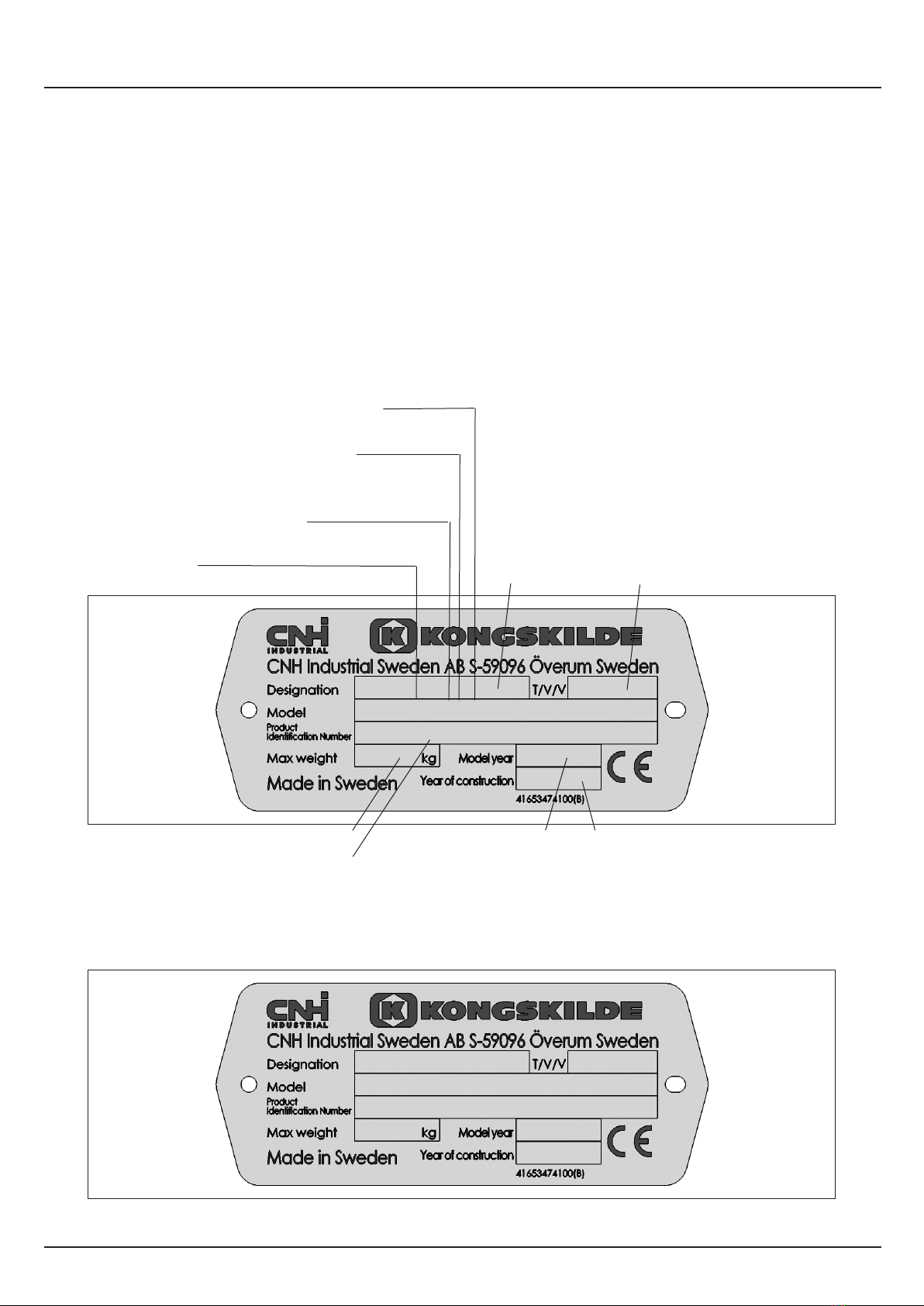
CNH INDUSTRIAL SWEDEN AB.
Bruksgatan 4, 59096 Överum, SWEDEN
Repræsenteret af Antoon Vermeulen, Leon Claeysstraat 3A, B8210 Zedelgem (Belgien),
som også har tilladelse til at indsamle teknisk dokumentation / vertreten durch Antoon
Vermeulen, Leon Claeysstraat 3A, B8210 Zedelgem (Belgium), der auch autorisiert ist,
die technische Akte zu erarbeiten / represented by Antoon Vermeulen, Leon Claeysstraat
3A, B8210 Zedelgem (Belgium), who is also authorised to compile the Technical File /
Répresentés par Antoon Vermeulen, Leon Claeysstraat 3A, B8210 Zedelgem (Belgique),
également autorisé à constituer le dossier technique / rappresentati da Antoon Vermeulen,
Leon Claeysstraat 3A, B8210 Zedelgem (Belgio), autorizzato a compilare il File tecnico
/ vertegenwoordigd door Antoon Vermeulen, Leon Claeysstraat 3A, B8210 Zedelgem
(Belgium), die tevens is gemachtigd om het Technisch Bestand samen te stellen /
representerade av Antoon Vermeulen, Leon Claeysstraat 3A, B8210 Zedelgem (Belgien),
som också har behörighet att sammanställa den tekniska dokumentationen / edustajamme
Antoon Vermeulenin, osoite Leon Claeysstraat 3A, B8210 Zedelgem (Belgium) välityksellä,
jolla on myös oikeus laatia tekninen tiedosto / representados por Antoon Vermeulen, Leon
Claeysstraat 3A, B8210 Zedelgem (Bélgica), quien además está autorizado para recopilar el
documento técnico / której przedstawicielem jest Antoon Vermeulen, Leon Claeysstraat 3A,
B8210 Zedelgem (Belgia), który jest również upoważniony do sporządzania dokumentacji
technicznej / представлявани от Антоон Вермьолен, Leon Claeysstraat 3A, B8210
Zedelgem (Белгия), с упълномощение също да състави Техническото досие / akiket
képvisel: Antoon Vermeulen, Leon Claeysstraat 3A, B8210 Zedelgem (Belgium), aki szintén
jogosult a műszaki dokumentumok összeállítására / v zastoupení Antoon Vermeulen, Leon
Claeysstraat 3A, B8210 Zedelgem (Belgium), s autorizací k tvorbě technického souboru
/ atstovaujami Antoon Vermeulen, Leon Claeysstraat 3A, B8210 Zedelgem (Belgija), taip
pat turintis teisę sudaryti technines bylas / v zastúpení Antoonom Vermeulenom, Leon
Claeysstraat 3A, B8210 Zedelgem (Belgicko), ktorý je oprávnený zostavovať technickú
dokumentáciu / reprezentaţi de Antoon Vermeulen, Leon Claeysstraat 3A, B8210 Zedelgem
(Belgia), care este, de asemenea, autorizat să compileze dosarul ethnic / esindajatega
Antoon Vermeulen, Leon Claeysstraat 3A, B8210 Zedelgem (Belgia), kellel on samuti
luba tehnilise faili koostamiseks / ki nas zastopa Antoon Vermeulen, Leon Claeysstraat
3A, B8210 Zedelgem (Belgija), ki je pooblaščen tudi za sestavo tehnične dokumentacije
/ εκπροσωπούμενοι από τον Antoon Vermeulen, Leon Claeysstraat 3A, B8210 Zedelgem
(Βέλγιο), με εξουσιοδότηση και για τη σύνταξη του Τεχνικού φακέλου / representados por
Antoon Vermeulen, Leon Claeysstraat 3A, B8210 Zedelgem (Bélgica), que também tem
autorização para compilar o Ficheiro Técnico / irrappreżentata minn Antoon Vermeulen

Leon Claeysstraat 3a, B8210 Zedelgem (Belġju), min huwa wkoll awtorizzat li tiġbor l-Fajl
Tekniku / Antoon Vermeulen, Leon Claeysstraat 3A, B8210, Zedelgem (Belgium), pārstāvēti,
kas ir pilnvarots arī sastādīt tehnisko reģistru
Erklærer hermed, at/ Erklären hiermit, daß/ Hereby declare that/ Déclare par la présente
que/ Dichiara che/ Verklaren hierbij dat/ Försäkrar härmed, att/ Vakuuttaa täten, että tuote/
Por el presente declara que/ Niniejszym deklaruje, że/ Декларирам, че/ Az alábbiakban
kijelentem, hogy/ Tímto prohlašuje, že/ Deklaruoja, kad/ Týmto prehlasujeme, že/ Prin
prezenta declar că/ Alljärgnevaga deklareerib, et/ Izjavljamo, da je/ Με το παρόν δηλώνω
ότι/ Abaixo declara que / Jiddikjaraw li / Apstiprinu, ka
- er i overensstemmelse med Maskindirektivets bestemmelser (Direktiv 2006/42/EF) og hvis
relevant også bestemmelserne i EMC-direktivet 2014/30/EU.
- In übereinstimmung mit den Bestimmungen der Maschinen-Richtlinie 2006/42/EG und
wenn erforderlich auch mit der EMC-Richtlinie 2014/30/EU hergestellt wurde.
- is in conformity with the provisions of the Machinery Directive 2006/42/EC and if relevant
also the provisions of the EMC Directive 2014/30/EU.
- est conforme aux dispositions de la Directive relatives aux machines 2006/42/CE et
également aux dispositions de la Directive sur la Directive EMC 2014/30/UE.
- é in conformita’ con la Direttiva Macchine 2006/42/CE e, se pertinente, anche alla Direttiva
alla Direttiva EMC 2014/30/UE.
- in overeenstemming is met de bepalingen van de Machine richtlijn 2006/42/EG en wanneer
relevant ook met de bepalingen van de EMC richtlijn 2014/30/EU.
- är i överensstämmelse med Maskindirektivets bestämmelser (Direktiv 2006/42/EG) och
om relevant också bestämmelserna i EMC-direktivet 2014/30/EU.
- täyttää Konedirektiivin (Direktiivi 2006/42/EY) määräykset ja oleellisilta osin myös EMC-
direktiivin 2014/30/EU.
- es conforme a la Directiva de Maquinaria 2006/42/CE y, si aplica, es conforme también a
la Directiva EMC 2014/30/EU.
- pozostaje w zgodzie z warunkami Dyrektywy Maszynowej 2006/42/WE i jeżeli ma to
zastosowanie również z warunkami Dyrektywy dot. kompatybilności elektro magnetycznej
EMC 2014/30/UE.
- отговаря на изискванията на Директивата за Машините 2006/42/EО и ако има
приложение на изискванията на Директивата за електромагнитна съвместимост
2014/30/EC.
- Megfelel a 2006/42/EK Gépi Eszközökre vonatkozó előírásoknak és amennyiben
felhasználásra kerül, a 2014/30/EU Elektromágneses kompatibilitás Irányelv feltételeinek.
- odpovídá základním požadavkům Strojní směrnice 2006/42/ES a jestliže to její uplatnění
vyžaduje i s podmínkami Směrnice 2014/30/EU týkající se elektromagnetické kompatibility.
- atitinka Mašinų direktyvos Nr. 2006/42/EB ir, jeigu taikoma, Elektromagnetinio suderinamumo
direktyvos Nr. 2014/30/ES reikalavimus.
MT MS
Plough
301626-320000

- je v súlade s podmienkami Smernice 2006/42/ES o strojných zariadeniach a pokiaľ si
to jeho uplatnenie vyžaduje aj s podmienkami Smernice 2014/30/EÚ o elektromagnetickej
kompatibilite.
- îndeplineşte prevederilor Directivei de Maşini 2006/42/CE şi dacă este utilizată de asemenea
cu prevederile Directivei referitoare la compatibilitatea electro-magnetică EMC 2014/30/UE.
- on vastavuses Masinate Direktiivi tingimustega 2006/42/EÜ ning sammuti juhul, kui on
tegemist sammuti on vastavuses Elektromagnetilise kokkusobivuse Direktiivitingimustega
EMC 2014/30/EL.
- z določili Direktive o strojih 2006/42/ES ter, če je to relevantno, tudi z določili EMC Direktive
2014/30/EU.
- παραμένει σύμφωνη με τους όρους της Οδηγίας περί Μηχανών 2006/42/ΕΚ και σε
περίπτωση που αυτό εφαρμόζεται και με τους όρους της Οδηγίας περί ηλεκτροµαγνητικής
συµβατότητας (ΗΜΣ) 2014/30/EE.
- Está de acordo com exigências das Directivas das Maquínarias 2006/42/CE e no caso em
que tiver igualmente aplicação com as exigências das Directivas referentes a compatibilidade
electromagnética EMC 2014/30/UE.
- tikkonforma mad-dispożizzjonijiet tad-Direttiva dwar il-Makkinarju 2006/42/KE u jekk
rilevanti wkoll mad-dispożizzjonijiet tad d-Direttiva EMC 2014/30/EU.
- atbilst mašīnu direktīvai 2006/42/EK, kā arī nepieciešamības gadījumā elektromagnētiskās
saderības direktīvai EMC 2014/30/ES.
Zedelgem
Antoon Vermeulen

1
FOREWORD
DEAR CUSTOMER!
Please read these instructions carefully. If you follow the instructions given, you can expect
good results along with a good economic return from your choice of plough.
If carefully operated, adjusted and maintained, the plough will meet all reasonable demands
made on it and will give you reliable service in years to come. Should you need further
instructions, which are not included in this manual, or require the help of experienced service
personnel, we advise you to contact one of our local representatives, which also will have
spare parts in stock.
It has always been the ambition of Kongskilde to constantly improve its products. Consequently,
in the interest of product improvement, no specication is nal or binding and we reserve
the right to alter the design of new machine series and equipment without previous notice.
CNH Industrial Sweden AB
Bruksgatan 4
S-59096 Överum
Sweden
Tel.: +45 61 80 50 00
E-mail: of[email protected]

2
MS MT KK EN 180103
Conventional Ploughs MS/MT
CONTENTS
FOREWORD ............................................................................................................1
1. INTRODUCTION..................................................................................................3
Description of function .................................................................................3
Identication of plough.................................................................................4
Safety Regulations.......................................................................................5
2. TECHNICAL DESCRIPTION................................................................................9
Checking the tractor prior to ploughing........................................................9
Preparation of the plough .......................................................................... 11
Mounting the plough on to the tractor........................................................ 11
Checking the plough..................................................................................12
3. BASIC SETTINGS..............................................................................................13
Basic settings of the plough.......................................................................13
Disc coulters ..............................................................................................15
Adjustment / Setting of skimming devices .................................................16
Troubleshooting - Ploughing......................................................................18
Adjustment of working width......................................................................19
4. STONE TRIP SYSTEMS....................................................................................21
Shear bolt protection..................................................................................21
Hydraulic stone trip system........................................................................21
Adjustment of operating pressure..............................................................22
Checking the accumulator .........................................................................23
5. DRIVING A CONVENTIONAL PLOUGH ...........................................................24
Useful operational points ...........................................................................24
6. MAINTENANCE .................................................................................................26
Replacement of wearing parts ..................................................................26
Parallelism and G-measurement of the mouldboards ...............................27
Tightening the bolts ...................................................................................28
Greasing of the beam hinge points............................................................28
Tyre pressure.............................................................................................29
Winter storage ...........................................................................................29
Lubrication chart ........................................................................................30
7. EXTRA EQUIPMENT .........................................................................................31
8. USEFUL ADVICE ...............................................................................................32
9. LIFTING POINTS ...............................................................................................33
10. TECHNICAL DATA ...........................................................................................34

3
1. INTRODUCTION
1. INTRODUCTION
DESCRIPTION OF FUNCTION
The plough is designed only for “Conventional ploughing”, and for transport between the
farm and the different elds.
MT ploughs that are equipped with a hydraulic stone trip system can be used for all types of
soil. MS ploughs that are equipped with a shear bolt protection are to be used only in soils
that are free of stones.
The plough is to be attached to the three-point linkage at the rear of the tractor, with the
hydraulic systems connected to the appropriate hydraulic outlets.
Cross-shaft
LandsidePoint Share
MouldboardMouldboard shin

4
MS MT KK EN 190108
Conventional Ploughs MS/MT
1. INTRODUCTION
IDENTIFICATION OF PLOUGH
Type designation
MT 3975-5975
MS 3975-5975
Beam height 75 or 80 cm
Plough body spacing 9=90 cm
Number of plough bodies
Machin type
Complete the sign below with the Machine type and Serial number of Your plough.
MT 4975
18 301626
Year of manufacturing
Serial number
PLOUGH
Designation
Model yearMax plough weight
Type / Variant / Version

5
1. INTRODUCTION
SAFETY REGULATIONS
READ THE INSTRUCTION MANUAL. SAFETY IS YOUR RESPONSIBILITY.
You should read the instruction manual before you change any
settings or start using the plough. The plough is designed and
manufactured with as many safety features as possible, but we
cannot foresee all possible circumstances that can involve safety
hazards with this machine.
Your responsibilities as owner or operator are to ensure the safety of any personnel in
connection with: the operation, transport, maintenance or storage of the machine. If you
have questions not answered in this manual, please contact your dealer or distributor.
Be aware of your responsibilities. The most important safety device is a safety conscious
operator, whose training and experience must include:
• Operator competence, the operator must be able to carry out a correct and
complete adjustment of settings and to ensure safe and reliable operation.
Training in safety issues is to be reviewed or repeated annually.
• Being aware of their environment to the extent that unforeseen safety issues that
may arise are dealt with to ensure the safety of all personnel (including operators,
maintenance personnel and bystanders).
This symbol means: SAFETY ALERT!
The safety decals in the instruction manual are used to highlight given
instructions that involve safety of all personnel. Failure to comply with
a given instruction could result in severe injury or death.
SAFETY ALERT decals Note! The decals on the machine can differ from the decals in this
instruction manual.
GENERAL SAFETY INSTRUCTIONS
Keep a safe distance
Do not stand under, on or close to the plough when it is in operation or when it is connected
to the tractor.
Support the Plough
Do not stand under, on or close to the plough if the plough is not properly supported.
Lower the plough
The plough should be lowered to the ground when standing still.
Front ballast weights
The front of the tractor should be tted with balance weights as required to maintain optimal
traction and directional stability. Ensure that at least 20% of the tractor’s weight is carried by
the front wheels.

6
MS MT KK EN 180103
Conventional Ploughs MS/MT
1. INTRODUCTION
Be alert
Ensure that no person is on, underneath or in the hazardous area of the plough during
transport, ploughing or when maneuvering the plough. Never work under a lifted plough!
Use the support leg
Always use the support leg when the plough is parked. Park the plough on level rm surface.
Do not allow passengers
Do not allow anyone to ride on the implement when it is being transported or while in
operation.
SAFETY WHEN CONNECTING AND DISCONNECTING THE PLOUGH
Risk for personal damage
An unintentional manoeuvre with the tractor may cause serious injury. Always make sure
that nobody is standing between the tractor and the machine during connection and
disconnection.
Make sure that the plough is locked with sufcient locking pins. During operation, negative
forces can occur that push one side of the cross shaft and the lower link of the quick coupling
upwards. There is a risk that the hook can release. Therefore, the quick coupling on the
lower links should be secured with a bolt.
Make sure the tractors gear is in neutral before starting the engine.
Make sure that there is no pressure in the hydraulic hoses
Before the tractor engine has stopped, make sure that there is no pressure in the hydraulic
hoses by activating the tractor spool valves to oating position.
Check the length of the hydraulic hoses
Check the length of the hydraulic hoses when the plough is lowered to working position.
Check that they are not too tense.
Check connection of hydraulic hoses
Make sure that the hydraulic hoses are connected to the correct hydraulic outlets on the
tractor. If connected incorrectly, the plough can move in an unforeseen way.
MAINTENANCE SAFETY
Avoid contact with oil and grease
To avoid oil and grease contact with your skin, wear protective gloves.
High oil pressure
The plough must be mounted to the tractor!
Be careful when the plough is examined for oil leaks or damaged ttings. Hydraulic oil under
pressure can penetrate the skin and cause serious damage. Always release the pressure
in the hydraulic system prior to maintenance work on the hydraulic system and make sure
that all components are correctly tightened before the system is set under pressure. Always
wear gloves and eye protection.
Never tamper with the gas lling valve on the accumulator!

7
1. INTRODUCTION
Do the maintenance regularly
Do the maintenance work regularly as it is described in this manual, section 6 MAINTENANCE.
Replace wearing parts as described. There is a risk of poor performance if the machine not
is maintained properly.
Retighten all nuts and bolts
Always remember to retighten all nuts and bolts after about 3 hours of use. Make sure that
bolts and nuts are tight at all times. Tightening torques are shown in section 6 MAINTENANCE.
Use protection gloves
Always use gloves when working with parts on the machine as they can have sharp edges.
TRANSPORT SAFETY
Beware of the length of the plough
The plough is long and does not completely follow the tractor in sharp turns. Avoid that the
plough’s rear end hits an obstacle. The tractors braking pedals must be locked together
during transport driving.
The stabilizers of the lower links
The stabilizers of the lower links should be locked when the plough is in transport position,
so that the plough is xed sideways.
Comply with the relevant trafc regulations
The operators have to observe relevant statutory or other national regulations dealing with
road safety and labor safety issues.
Drive safe, max 25km/h
Be a safe and courteous driver, yield to oncoming trafc. In all situations, do not exceed 25
km/h.

8
MS MT KK EN 180103
Conventional Ploughs MS/MT
1. INTRODUCTION
WARNING DECALS
Explanations
4165 99101 00 Read the manual!
Carefully read the instructions and observe all safety instructions
before you connect the machine to the tractor.
4165 98301 00 Warning hazardous area!
It is not allowed to be within the hazardous area, on, under or close to
the machine during transport driving or operation. Never work under a
lifted plough. Always make sure that nobody is standing between the
tractor and the machine.
4165 98300 00 High oil pressure!
Be careful when oil leaks or damaged ttings are examined. Hydraulic
oil under pressure can be dangerous. Always release the pressure in
the hydraulic system prior to maintenance work on the hydraulic system
and make sure that all components are correct tightened before the
system is set under pressure. Always wear gloves and eye protection.
4165 99102 00 Support leg
Do not stand close to the plough if not properly supported. When
parking the plough always use the support leg.
4165 25073 00 Warning! Risk of crushing
Risk of crushing injuries. Be careful!

9
2. TECHNICAL DESCRIPTION
CHECKING THE TRACTOR PRIOR TO PLOUGHING
TRACTOR SIZE
The tractor must have an appropriate size to operate the plough safely! Make sure that at
least 20% of the tractor`s weight is loaded onto the front axle.
FUNCTION OF THE THREE-POINT HITCH
The design of the three-point linkage is based on the principle that the tractor and the plough
should operate as one unit. This function is depending of the settings for the lower links and
the top link. These components must therefore be maintained in a condition that enables
them to be easily adjusted.
HYDRAULICS
Following external hydraulic outlets are required:
MT 1 single-acting
If the plough is equipped with hydraulic front furrow adjustment cylinder one extra double
acting hydraulic outlet is required. Familarize yourself with the hydraulic systems of the
tractor.
WHEEL ADJUSTMENT - TRACK WIDTH
For ploughing purposes, track width is always measured between the inside walls on the
tractor tyres.
The measurement between the inner walls of the front wheels must be at least equal to the
inner measurement between the rear wheels, but may be up to 10 cm wider. The distance
between wheels must be symmetrical, relative to the centre line of the tractor.
kg 20%

10
MS MT KK EN 180103
Conventional Ploughs MS/MT
2. TECHNICAL DESCRIPTION
The following track widths are recommended: 1200 - 1500 mm
Ideal track width = 3 x the furrow width + 100-150 mm
(Example: 16” furrow width 3 x 400 + 125 = 1325 mm).
When ploughing with “wide tyres” the outside walls of the front and the rear tyres should be
parallel. The furrow widener knives should be mounted on the last plough body.
Note: Large mounted ploughs can affect the stability of the tractor.
TYRE PRESSURES
Both tyre life and optimum traction are achieved by using the correct tyre pressure. Over-
ination will increase wheel slip. Make sure that both rear tyres are inated to the same
pressure.
FRONT BALLAST WEIGHTS
The front of the tractor should be tted with balance weights as required to maintain optimal
traction and directional stability.
LIGHTS
The tractor must be equipped with working lights when plowing in the dark.
x

11
2. TECHNICAL DESCRIPTION
PREPARATION OF THE PLOUGH
Check that the quick-couplings on the hydraulic hoses are the same type as the quick-
couplings on the tractor. If required, t the correct quick-couplings, to suit your tractor.
Check that the cross-shaft on the plough has the correct category to suit your tractor.
Cross shafts are available in different categories:
Cat. 2 means ø 28 mm cross-shaft pins
Cat. 3 means ø 36 mm cross-shaft pins
The length of the cross shaft is determined by the track widths of the tractor and the spacing
of the lower links on the tractor’s rear axle. When the spacing is > 550 mm on the tractor’s
rear axle, use the 965 mm long cross shaft.
Cat. B C
2 825 ø 28
2L 965 ø 28
3 965 ø 36
MOUNTING THE PLOUGH ON TO THE TRACTOR
Make sure that the lower links can be lowered approximately 20 cm below the cross shaft of
the plough before the plough is mounted onto the tractor.
Check that the link ball joints are of the same category as the cross shaft pins. Lock the
cross-shaft into the tractor’s lower links with sufcient locking pins.
The stabilizers for the lower links should be adjusted so that the plough can move freely in
working position, but when raised the side movements should be limited.
The top link should be mounted slightly higher on the plough than on the tractor.
Consult the tractor manufacturers manual on mounting implements
and safe working methods.
B
C

12
MS MT KK EN 180103
Conventional Ploughs MS/MT
2. TECHNICAL DESCRIPTION
CHECKING THE PLOUGH
• Check the tightness of all bolts and nuts
• Grease all lubrication points
• Check the tyre pressure and adjust if necessary. See chapter 6. MAINTENANCE,
TYRE PRESSURE
• Check that the desired furrow width is correctly set, see chapter 3. BASIC
SETTINGS, FIRST FURROW WIDTH.
• Mouldboards: In order to make it easy starting up a new plough, the frontside
of the mouldboards, skim coulters and coverboards are protected with wax.
The wax do not have to be removed before the plough is used for the rst time.
• Check the disc coulter and skim coulter settings and adjust them so that the
settings are identical.
• Raise the plough and fold up the support leg.
• Always remember to re-tighten all nuts and bolts after about 3 hours of
use, apart from that you should make sure that bolt and nuts are tight at all
times.
STONE TRIP SYSTEM
Check the working pressure by reading the pressure gauge. For suitable working pressure,
see section: 4. STONE TRIP SYSTEM, ADJUSTING OF OPERATING PRESSURE.

13
3. BASIC SETTINGS
3. BASIC SETTINGS
BASIC SETTINGS OF THE PLOUGH
The basic setting can be started when the desired ploughing depth has been reached and
when the tractor wheels are running in a furrow with the same depth.
1. VERTICAL ADJUSTMENT
The beams should be at right angle (90 °) to the ground. If necessary, make adjustments
by using the right-hand lower link of the tractor. The vertical setting can be checked by
observing the plough from the rear.
2. HORIZONTAL AND DEPTH ADJUSTMENTS
Mount the top link so that it is 5 - 10 cm lower on the tractor than on the plough when in
working position. The top link can be mounted in three positions on the plough. The slotted
centre hole can be used on tractors equipped with lower link sensing hydraulic system, and
it should be used with large ploughs. For ploughing in hard conditions using ploughs with
3-4 plough bodys, the top link should be attached in a xed position to prevent the rear
plough body from working too shallow.
Adjust the length of the top link so that the depth of ploughing is the same for the rst and
last bodies. The frame will now run parallel to the ground.
90°
ll

14
MS MT KK EN 180103
Conventional Ploughs MS/MT
3. BASIC SETTINGS
3. FIRST FURROW WIDTH
Ensure that the lower links are loose so the plough can move freely.
For ploughs equipped with a hydraulic control of the rst furrow width, the following applies:
Place the hydraulic cylinder in a central position so that it can be adjusted in both directions.
Check that the cross-shaft has the correct angle adjustment, see section 3. ADJUSTMENT
OF WORKING WIDTH. The adjustment is made with the turnbuckle.
If the width of the rst furrow is not correct, loosening the four nuts Aand move the cross-
shaft sideways to achieve the correct width of the rst furrow.
Drive forwards a few meters and checks the result. When the right width of the front furrow is
reached, tighten the four nuts. The rst furrow can now be made wider or narrower by means
of the hydraulic cylinder, which moves the plough laterally on the cross-shaft. On ploughs
with mechanical control of crossshaft, the basic adjustment of the cross-shaft is done in the
same way. Subsequently, the width of the rst furrow can be temporarily adjusted using the
turnbuckle.
Lengthened turnbuckle gives wider rst furrow
Shortened turnbuckle gives narrower rst furrow
AA

15
3. BASIC SETTINGS
DISC COULTERS
The purpose of the disc coulters is to make a vertical cut, separating the furrow slices.
There are two types of disc coulters, xed and spring loaded. When ploughing in stony or
very heavy soils, the springloaded type of disc coulter should be used. This is to protect the
coulters and to ensure that they do not act like a support wheel, carrying the plough, which
would prevent it from maintaining a correct ploughing depth.
Side and depth adjustment of disc coulters
The coulters should be set to produce a clean, continuous cut. Under normal conditions,
the cut should be made 10 - 20 mm outside the landside, depending on type and condition
of soil. The coulters are set individually by loosening the nut on bracket Aand turning the
coulter shank sideways.
Depth adjustment of disc coulters
To maintain a favourable cutting angle towards the surface, the disc coulters should never
be set deeper in the ground than 1/3 of their diameter.
Depth adjustment is carried out by tting the coulter arm to different positions, B. This applies
for both xed and spring loaded disc coulters.
Make sure that all disc coulters on the plough are set to the same depth and are on an equal
distance from the landsides.
ATTENSION! Be alert, there is always a risk for injuries when
adjusting disc coulters and skimmers.
B
A
A
A
B
10-20 mm

16
MS MT KK EN 180103
Conventional Ploughs MS/MT
3. BASIC SETTINGS
ADJUSTMENT / SETTING OF SKIMMING DEVICES
The basic purpose of the skimming devices is to cut off and turn down a corner of the surface
layer with crop residues and weeds so that these are well buried. Properly used skimming
devices give the best mechanical weed control. Three different types of skimming devices
are available for this purpose. All skimmers are equipped with shear bolt protection (Part no.
4165 20376 00)
Skim coulter EG
Skim coulter EG is used to advantage when good weed control is important and when
ploughing grasslands. It works well in rmer soils, which produces a continuous furrow slice.
The depth should not be set deeper than that a corner of the furrow slice is cut off and turned
down. (Maximum 50 mm at the point).
When disc coulters are not mounted, the point of the skim coulter should be set to run about
10 - 20 mm outside the landside. When disc coulters are mounted, the skim coulters should
run beside the disc coulters, with the points about 10 mm away from the disc.
Manure skimmer EM
Recommended for deeper skimming and heavy trash. The convex mouldboard allows the
trash to go on both sides of the skim shank. Works well without disc coulter.
The point of the manure skimmer should be set to cut approximately 10 - 20 mm outside the
landside.
Coverboard
The coverboard does not affect the diagonal clearance of the plough. As a result, it can be
used to advantage in loose soils and where considerable quantities of straw are present, but
not in sticky soils.
The operation of the coverboard is dependent on the depth and speed of ploughing. The
front of the coverboard should always be in contact with the mouldboard shin, whereas the
outer section can be adjusted vertically to suit the ploughing depth.
NOTE: The coverboard should only cut off a small corner of the furrow
slice.
Skim coulter EG Manure
skimmer EM
Coverboard
This manual suits for next models
5
Table of contents
Popular Tractor Accessories manuals by other brands

Avantco
Avantco Backhoe 260 Operator's manual for Attachment

Avantco
Avantco Dozer blade 1400 Operator's manual for Attachment

Avantco
Avantco A425119 Operator's manual for Attachment

Nogueira
Nogueira VFN-9000 instruction manual

MacDon
MacDon R1 Series Operator's manual

Bradco
Bradco HP400 Operator and parts manual