AUFSTELLANLEITUNG
18804 Rollschlitten für Digitalpianos
BESTIMMUNGSGEMÄSSER GEBRAUCH
Der 11804 Rollschlitten dient als bewegliche Unterlage fürs Digitalpiano und
verleiht ihm so Mobilität auf der Bühne, im Studio, im Proberaum und in Ihrem
Zuhause. Zudem eignet er sich nicht nur für den Transport. Dank der geringen
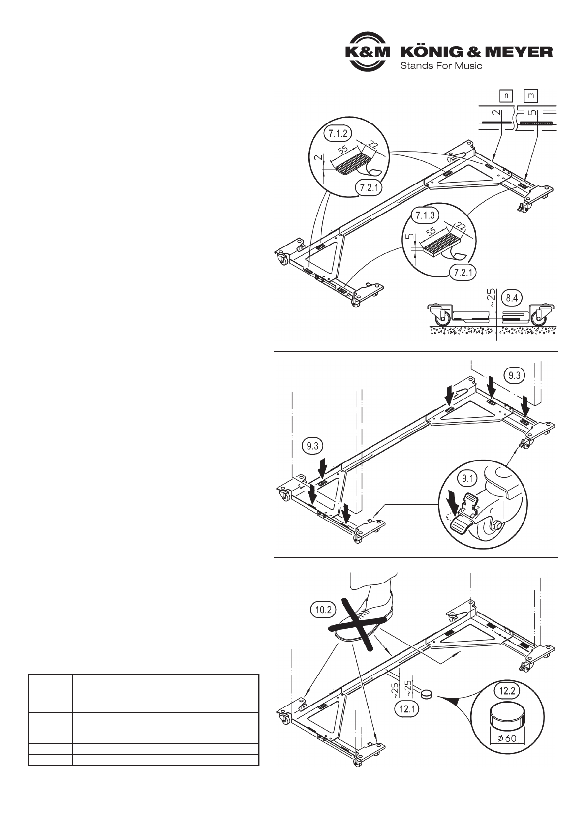
Abstellhöhe (25 mm) bietet sich der Verbleib des E-Pianos auf dem Rollschlitten
auch während des Spielens geradezu an.
MERKMALE und FÄHIGKEITEN
- Geeignet soweit uns bekannt für alle gängigen E-Pianos
- Stufenlos einstellbar in Breite (1038-1525 mm) und Tiefe (304-526 mm)
- Der Rollschlitten gleitet sanft auf acht hochwertigen Laufrollen:
-- ø 50 x 18 mm, - kugelgelagert, - Stahlgehäuse, - TPE-gummibereift
-- zwei der Laufrollen sind per Fuß feststellbar und fixieren den Standort
SICHERHEITSHINWEISE
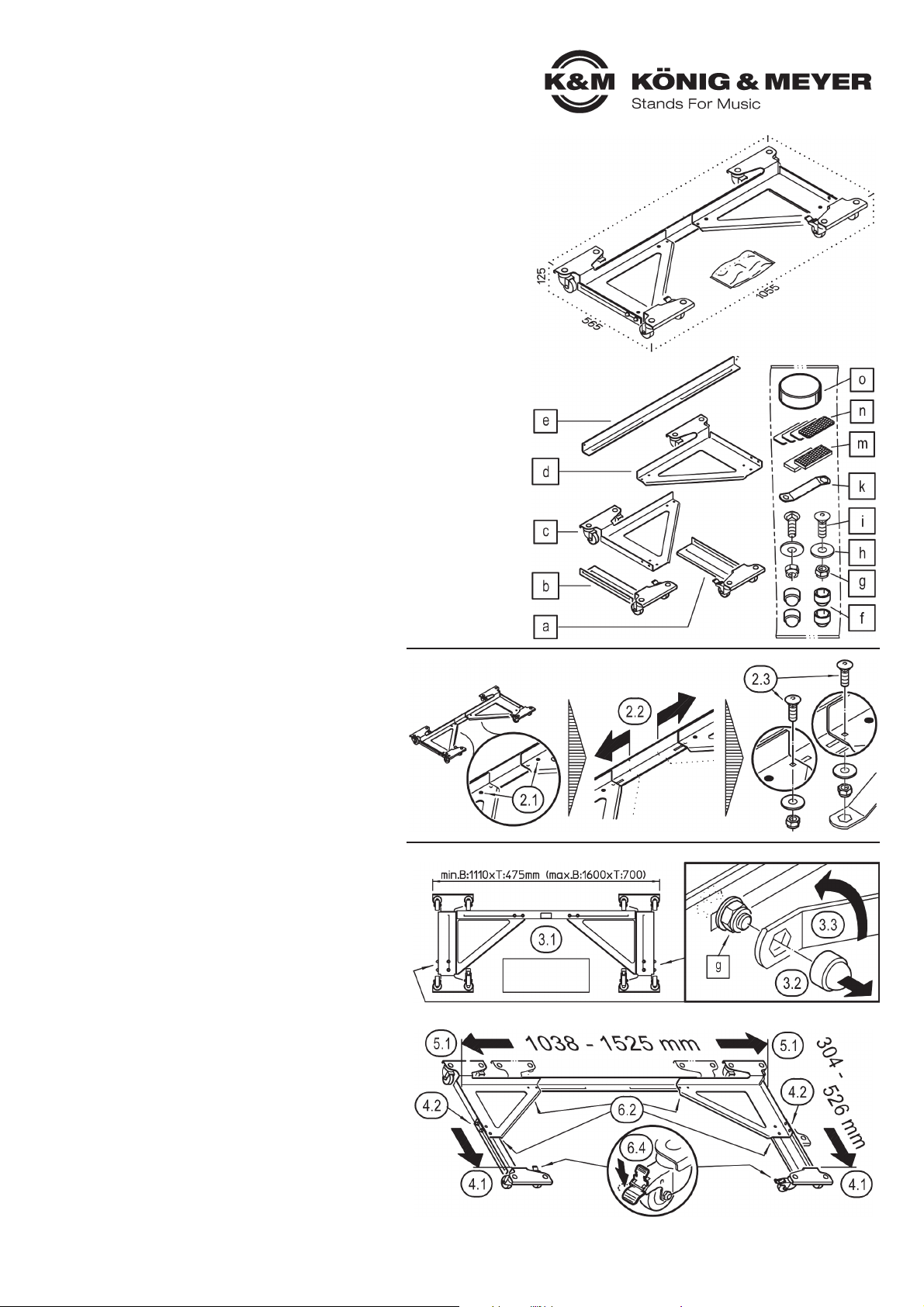
1. BESTANDTEILE
Bitte Sichtprüfung vornehmen, ob alle Teile vollständig
vorhanden und soweit erkennbar in Ordnung sind.
Das Produkt ist zum großen Teil bereits vormontiert und besteht aus:
aRollenhalter klein, rechts (2 Rollen, 1x feststellbar)
bRollenhalter klein, links (2 Rollen, 1x feststellbar)
cRollenhalter links (2 Rollen)
dRollenhalter rechts (2 Rollen)
eVerbindungswinkel
ZUBEHÖRBEUTEL:
f4x Schutzkappen SW8 ø 11 mm (zur Abdeckung der seitlichen Gewinde)
g2x Sicherungsmutter M5 h2x U-Scheibe ø 5,3/15 mm
i2x Schloßschraube M5 x 15 mm kSchlüssel SW8/SW13
m2x Filzstanzteil t=5 mm, selbstklebend (für: a/bRollenhalter klein li./re.)
n4x Filzstanzteil t=2 mm, selbstklebend (für: c/dRollenhalter li./re.)
oDistanzscheibe mit Filzunterlage ø 60 x 25 mm
2.-8. MONTAGE und HANDHABUNG
2. MONTAGE der zwei SCHRAUBENSÄTZE (g-h-i)
2.1 Jede der beide Rollenhalter c, dist zunächst nur mit einer Schraube
2.1 am Verbindungswinkel ebefestigt
2.2 Beide Rollenhalter c, dein Stück weit auseinanderschieben.
2.3 Aus dem Zubehörbeutel die zwei Schraubensätze g-h-i entnehmen
2.3 und beide Rollenhalter nun mit einer zweiten Verschraubung am
2.3 Verbindungswinkel ebefestigen.
3. ROLLSCHLITTEN VORBEREITEN
3.1 Rollschlitten so auslegen, dass die Rollen nach oben zeigen.
3.2 Seitliche Schutzkappen fabziehen
3.2 HINWEIS: Im Falle der Erstinstallation befinden sich diese Kappen f
3.2 HINWEIS: noch im Zubehörbeutel
3.3 Sämtliche 12 Sicherungsmuttern glockern (ca. 1 Umdrehung); dazu
3.3 Schlüssel SW8 kbenutzen.
3.4 Rollschlitten wieder vorsichtig auf den Rollen abstellen
4. TIEFE EINSTELLEN
4.1 Tiefe des Digitalpianos abnehmen und die beiden Rollenhalter, klein
4.1 a, bdementsprechend ausfahren (max. 526 mm).
4.2 Die vier seitlichen Sicherungsmuttern gfestziehen;
4.2 anschließend auch die vier Schutzkappen faufpressen.
5. BREITE EINSTELLEN
5.1 Breite des Digitalpianos abnehmen und die beiden Rollenhalter c, d
5.1 dementsprechend ausfahren (max. 1525 mm).
6. GEWÄHLTE EINSTELLUNG FIXIEREN
6.1 Rollschlitten erneut umdrehen, so dass die Rollen nach oben zeigen.
6.1 HINWEIS: Damit sich die gewählte TIEFE 4und BREITE 5dabei nicht
6.1 HINWEIS: ungewollt verstellt, empfehlen wir mit zwei Personen zu arbeiten
6.2 Die acht verbliebenen Sicherungsmuttern gfestziehen (Schlüssel k, SW8)
6.3 Rollschlitten wieder auf den Rollen abstellen.
6.4 Feststeller der Rollen a, bbetätigen. Sobald diese eingerastet sind, ist
6.4 der Schlitten auf der Ebene gegen unbeabsichtigtes Wegrollen gesichert.
ALLGEMEIN
- Bitte beachten Sie die Angaben dieser Aufstellanleitung.
- Ebenfalls zu beachten sind Sicherheitsanweisungen und Anleitungen der eingesetzten Digitalpianos.
- Die Möglichkeit, das Produkt zu verstellen, birgt naturgemäß Einklemmgefahren. Umsichtige und
-aufmerksame Handhabung bei Aufbau, Betrieb, Abbau und Wartung sind daher unverzichtbar.
- Vor Nässe schützen oder ggf. zeitnah Bestandteile trockenreiben.
BETRIEB
- Vor Benutzung auf Vollständigkeit und Funktionsfähigkeit prüfen.
- Beschädigte Teile müssen vor Gebrauch entweder ersetzt oder erst wieder Instand gesetzt werden.
- Der sichere Sitz des Digitalpianos ist stets zu gewährleisten. Dies geschieht insbesondere durch
-die Anpassung der Rollschlitten an die jeweiligen Abmessungen des Instruments.
- Auf feste Schraubverbindungen aller beteiligten Artikel ist zu achten.
- Während des Transports ist das Ensemble stets mit der Hand am Digitalpiano zu führen.
- Den Rollschlitten (auch unbelastet) nicht auf schiefer Ebene abstellen.
- Im Standbetrieb sind jeweils beide Fußrollenbremsen festzustellen.
- Bei ungünstigen Bodenverhältnissen (weiche Beläge, schiefe Ebenen, Absätze, Hindernisse u. ä.)
-bitte erhöhte Vorsicht walten lassen. Das gilt sowohl für den Transport- als auch den Standbetrieb.
-(Mögliche Gefährdungen sind: Erschütterungen, selbstständiges Rollen, Kippen, Anstoßen).
- Das Abstellen der Füße auf dem Rollschlitten ist nicht erlaubt.
- Zur Reinigung ein leicht feuchtes Tuch und ein nicht scheuerndes Reinigungsmittel benutzen.
Vielen Dank, dass Sie sich für dieses Produkt entschieden haben. Bitte lesen und beachten Sie vor
Aufbau und Betrieb dieses Produkts sorgfältig diese Anleitung. Sie informiert Sie über alle wichtigen
Schritte um eine sichere Handhabung zu gewährleisten. Wir empfehlen, sie auch für den späteren
Gebrauch aufzubewahren.
KÖNIG & MEYER GmbH & Co. KG
Kiesweg 2, 97877 Wertheim, www.k-m.de
18804-000-55 Rev.5b 03-80-434-00 5/21
1. BESTANDTEILE
2. MONTAGE der zwei SCHRAUBENSÄTZE
3. ROLLSCHLITTEN VORBEREITEN
4. TIEFE EINSTELLEN - 5. BREITE EINSTELLEN - 6. GEWÄHLTE EINSTELLUNG FIXIEREN
Ansicht von
unten
Außenmaße (B x T)