Konig & Meyer 26750 User manual

KÖNIG & MEYER GmbH & Co. KG
Kiesweg 2, 97877 Wertheim, www.k-m.de
26750-022-55 Rev.04 03-80-864-00 4/22
26750 Boxenstativ
BESTIMMUNGSMÄSSER GEBRAUCH
Bodenstativ zum Aufstecken von Lautsprechern und Monitoren
Insbesondere geeignet für Präsentationen, Heim und Studio dank
ansprechender zurückhaltender Optik und platzsparender Bauart
MERKMALE & FÄHIGKEITEN
- Tragfähigkeit max. 35 kg (siehe Sicherheitshinweise: C)
- Kreisrunder, flacher Guß-Bodensockel (ø 450 mm, 6,8 kg)
- Doppelt gesicherte Stahlrohrkombination
- Höhenverstellbar von 930 - 1430 mm
- Mit kegeliger Aufsteckhilfe für 35/36 mm-Lautsprecherbuchsen
SICHERHEITSHINWEISE
A. ALLGEMEIN
A. - Das Stativ ist vor und nach der Benutzung einer Sichtprüfung zu unterziehen.
A. -Beschädigte oder unvollständige Stative dürfen nicht eingesetzt werden bzw.
A. -erst wieder nach Instandsetzung
A. - Auf geeigneten, d.h. ebenen und tragfähigen Untergrund achten
A. - Bei Positionswechsel des Stativs Traglast ggf. vorher abnehmen
A. - Unbefugte fernhalten
A. - Angaben dieser Anleitung beachten und für später aufbewahren
B. MONTAGEHINWEISE
B. - Bodensockel und auch Rohrkombination mit Vorsicht handhaben, insbe-
B. -sondere nicht fallenlassen (Quetschgefahr, Schäden am Boden etc.)
B. - Auf feste Schraubverbindungen achten (Sockel, Rohre, Traglast)
C. TRAGFÄHIGKEIT
C. - Die Tragfähigkeit von max. 35 kg gilt ausschließlich für Lasten, die genau
C. -senkrecht auf die Rohrkombination einwirken.
C. -Dies ist NICHT gegeben…
C. -a. …bei außerzentrischer Belastung, d.h. der Schwerpunkt der Traglast
C. -a. befindet sich nicht direkt über der Rohrkombination,
C. -b. …bei schräg stehendem Stativ (z.B. bei geneigtem Untergrund
C. -b. oder auch bei lockerer Verschraubung des Grundrohres) sowie
C. -c. …bei externen Einflüssen und Störungen (Zerren am Stativ,
C. -c. Stöße von Passanten, Windlasten, Erschütterungen etc.)
C. -So entstehen KIPP-Gefahren welche die angegebene Tragfähigkeit
C. -von max. 35 kg erheblich mindern.
D. AUS-/EINFAHREN DER TRAGLAST
D. - Stets von zwei befähigten Personen (P1, P2) durchführen lassen
D. -P1: hält das Auszugrohr mitsamt Traglast fest und sicher;
D. -P2: sichert die gewählte Höhe durch Einrasten des
D. -P2: Hakens 4.5 und Anziehen der Klemmschraube 4.6.
E. DEMONTAGE
E. - Immer zuerst die Traglast vom Stativ abheben - erst danach mit dem
E. -Einfahren bzw. der Demontage des Stativs beginnen.
AUFSTELLANLEITUNG
1. BESTANDTEILE
Nach dem Auspacken Sichtprüfung vornehmen, ob alle Teile vorhanden
und - soweit erkennbar - unbeschädigt sind.
aSockel/Bodenplatte ø 450 mm
bRohrkombination kpl. bestehend aus:
bb.1 M20-Gewindebolzen, b.2 Grundrohr, b.3 Spannschelle,
bb.4 Auszugrohr, b.5 Aufsteckhilfe
cGebrauchsanleitung
2. ZUSAMMENBAU
2.1 Bodenplatte amit Filzschonern nach unten auslegen.
2.2 Gewindebolzen b.1 des Grundrohres bis zum Anschlag
2.2 fest in die Bodenplatte aeinschrauben.
2.3 HINWEIS!
2.3 Zwischen Rohr und Platte darf sich kein Luftspalt befinden.
2.3 Verschraubung bitte regelmäßig auf Festigkeit prüfen und
2.3 diese ggf. nachziehen.
BENUTZERHINWEISE / FUNKTIONEN
3. VERBINDUNG TRAGLAST - STATIV
Um die Traglast (Lautsprecher/Monitor) aufzubringen, muss
diese entweder bereits bauartbedingt…
3.1 …über eine Einsteckbuchse (ø 35/36 mm) verfügen oder
mit einem entsprechenden Teil nachgerüstet werden.
Möglich sind:
3.2 Anschraubflansche (Bsp. K&M 195/8, 24281)
3.3 Flanschbuchsen (Bsp. K&M 19654, 19656)
1. BESTANDTEILE
2. ZUSAMMENBAU
3. VERBINDUNG
3. TRAGLAST
3. - STATIV
Vielen Dank, dass Sie sich für dieses Produkt entschieden haben. Bitte lesen und
beachten Sie vor Aufbau und Betrieb dieses Produktes sorgfältig diese Anleitung.
Sie informiert Sie über alle wichtigen Schritte um eine sichere Handhabung zu
gewährleisten. Wir empfehlen, sie auch für den späteren Gebrauch aufzubewahren.

4./5. TRAGLAST AUFBRINGEN / EINSTELLEN DER HÖHE
BEACHTE!
- Unterschätzen Sie nicht das Gewicht des Lautsprechers.
- Das Aufbringen sowie Aus- und Einfahren der Traglast muss durch
-befähigtes, d.h. fachlich und körperlich geeignetes Personal erfolgen.
- Aufmerksamkeit und Kommunikation zwischen den Bedienern ist unabdingbar.
- Auszugrohr während der Höhenverstellung stets mit festem Griff halten 4.2 bei gleichzeitiger
-Bereitschaft sofort die Flügelmutter 4.6 festzuziehen (z.B. bei ungewolltem Durchrutschen der Traglast).
Wir empfehlen, zuerst die gewünschte Höhe einzustellen,
diese zu sichern und anschließend die Traglast aufzubringen.
Falls das nicht möglich ist, muss eine dazu befähigte
Person (P1) das beladene Auszugrohr halten, während
eine weitere Person (P2) die Sicherungselemente
Sicherungshaken 4.4 und Flügelmutter 4.6 bedient.
(in mm)
Wir empfehlen, zunächst die Traglast abzuheben und erst danach das Auszugrohr einzufahren. Falls dies
nicht möglich ist, muss eine dazu befähigte Person (P1) das beladene Auszugrohr halten, während eine
weitere Person (P2) die Sicherungselemente Sicherungshaken 5.5 und Flügelschraube 5.6 bedient.
4.1 Flügelmutter der Spannschelle b.3 etwas lösen.
4.2 Auszugrohr b.4 anheben, wobei sich…
4.3 …der Sicherungshaken automatisch entriegelt
4.3 (und auch in entriegelter Stellung verbleibt).
4.4 Der Sicherungshaken muss also aktiv in die passende
4.4 Aussparung des Auszugrohres gedrückt werden.
4.5 Sobald der Haken eingetaucht ist, wird das Rohr
4.5 um 2 mm abgesenkt, wodurch der Sicherungshaken
4.5 gegen ungewolltes Ausrasten gesichert ist.
4.6 Flügelmutter wieder festziehen.
PRÜFEN, INSTANDHALTEN, REINIGEN
5.1 Flügelmutter der Spannschelle b.3 etwas lösen.
5.2 Zunächst Auszugrohr b.4 etwas anheben…
5.3 …wodurch der Sicherungshaken automatisch
5.3 entriegelt.
5.4 Anschließend Auszugrohr einfahren lassen und…
5.5 …Sicherungshaken wieder in die vorgesehene
5.5 Öffnung drücken und in das Rohr einhaken lassen.
5.6 Flügelmutter wieder festziehen.
TECHNISCHE DATEN / SPEZIFIKATIONEN
FEHLERSUCHE (F) und BESEITIGUNG (B)
Material
Sockelplatte: Grauguss, schwarz gepulvert
Rohre, Sicherungshaken: Stahl, schwarz gepulvert
Gewinde: Stahl verzinkt
Schelle, Schalen, Kappen: PA-6
Tragfähigkeit max. 35 kg zentrische Last
Abmessungen
Sockelplatte: ø 450 mm, H = 21 mm
Rohrkombination: ø 42 / ø 35 mm
Höhe: min. 930 - max. 1430 mm (5 x 100 mm)
Karton L x B x H: 1010 x 100 x 55 mm
Gewicht netto: 8,5 kg, brutto: 9,1 kg
F: Stativ kippelt bzw. steht schief:
F: B: Untergrund auf Ebenheit prüfen.
F: B: Sockelplatte auf Ebenheit prüfen.
F: B: Festsitz der Schrauben an Grundrohr und
F: B: Spannschelle prüfen und ggf. nachziehen.
F: Auszugrohr b.4 fährt ungewollt ein:
F: B: Sicherungshaken in Aussparung drücken und Flügelmutter festziehen
F: B: (4.4-4.6).
F: Lautsprecher/Monitor sitzt schief:
F: B: Ein kleiner Luftspalt zwischen Auszugrohr und Einsteckbuchse ist normal
F: B: und notwendig, um ein Verkeilen der Box zu verhindern. Dies kann zu
F: B: einem leicht schiefen Sitz der Box führen.
F: B: Durch Montage des Ausgleichsadapter 85890 wir der Luftspalt ausgefüllt.
F: B: Der Durchmesser von US-Boxen beträgt 38,1 mm (1 -1/2"). Diese Distanz
F: B: wird durch den Einsatz der Adapterhülse 21326 ausgeglichen.
4. AUSFAHREN 6. ABMESSUNGEN
5. EINFAHREN
- Schonender Umgang mit dem Distanzrohr erhält die Teleskopierbarkeit, die Tragkraft
-und die Sicherheit der Installation.
- Bei Wartungsarbeiten - stets im unbelasteten Zustand - auf mögliche Gefährdungen
-achten (Einklemmen, Anstoßen, Kippen).
- Zur Reinigung und Pflege ein leicht feuchtes Tuch und ein nicht scheuerndes
-Reinigungsmittel benutzen.

KÖNIG & MEYER GmbH & Co. KG
Kiesweg 2, 97877 Wertheim, www.k-m.de
26750-022-55 Rev.04 03-80-864-00 4/22
26750 Speaker stand
INTENDED USE
This floor stand enables you to attach speakers and monitors
Thanks to the attractive contemporary look plus the space-saving
design the stand is especially suited for presentations, studio and
home
FEATURES & CAPABILITIES
- Load-bearing capacity 35 kg (see safety instructions: section: C)
- Round, flat cast-iron base (ø 450 mm, 6.8 kg)
- Double secured steel tube combination
- Height adjustable from 930 - 1430 mm
- With cone-shaped mounting aid for 35/36 mm speaker enclosures
SAFETY INSTRUCTIONS
A. GENERAL
A. - The stand should be visually inspected before and after use.
A. -Damaged or incomplete stands should not be used or only used after repair.
A. - Please ensure that the floor is suitable, i.e. level and stable
A. - If necessary, remove the load before you change the position of the stand
A. - Keep unauthorized persons away
A. - Observe the instruction manual and keep it for future reference
B. MOUNTING INSTRUCTIONS
B. - Handle the base and tube combination with care and do not drop
B. -(risk of crushing, damage to the floor, etc.)
B. - Make sure that the screw connections are tight (base, tubes, load)
C. LOAD-BEARING CAPACITY
C. - The max. load capacity of 35 kg applies exclusively to loads which
C. -act exactly vertically on the tube combination.
C. -This is NOT given…
C. -a. …with off-centre loads, i.e. the centre of gravity of the load is not
C. -a. directly above the tube combination,
C. -b. …when the stand is at an angle (e.g. when the floor is inclined or
C. -b. if the base tube is screwed loosely) as well as
C. -c. …in case of external influences and disturbances (tugging on the
C. -c. stand, shocks from passers-by, wind forces, vibrations, etc.)
C. -This creates TILTING hazards which significantly reduce the specified
C. -load-bearing capacity of max. 35 kg.
D. EXTENDING/RETRACTING THE LOAD
D. - This should be always carried out by two competent persons (P1, P2)
D. -P1: holds the extension tube together with the load firmly and securely;
D. -P2: secures the selected height by engaging the safety hook 4.5
D. -P2: and tightening the clamping screw 4.6.
E. DISASSEMBLY
E. - Always lift the load from the stand first - only then start retracting or
E. -dismantling the stand.
SET-UP INSTRUCTIONS
1. COMPONENTS
After unpacking, visually check whether all parts are present and
- as far as can be detected - undamaged.
aBase/floor plate ø 450 mm
bTube combination consisting of:
bb.1 M20 threaded bolt, b.2 base tube, b.3 tension clamp,
bb.4 extension tube, b.5 mounting aid
cInstruction manual
2. ASSEMBLY
2.1 Lay out base plate awith felt pads facing downwards.
2.2 Screw the threaded bolt b.1 of the base tube into the
2.2 base plate a up to stop.
2.3 NOTE!
2.3 There should be no air gap between the tube and the plate.
2.3 Please check screw connection regularly for tightness and
2.3 retighten if necessary.
USER INSTRUCTIONS / FUNCTIONS
3. CONNECTION LOAD - STAND
In order to attach the load (loudspeaker/monitor), it should be
equipped with…
3.1 …a plug-in socket (ø 35/36 mm) or be upgraded with a
corresponding part.
You may use:
3.2 Mounting adapters (e.g. K&M 195/8, 24281)
3.3 Flange adapters (e.g. K&M 19654, 19656)
1. COMPONENTS
2. ASSEMBLY
3. CONNECTION
3. LOAD - STAND
Thank you for choosing this product. Please read and follow the instructions carefully.
They inform you about all the important steps concerning assembly and handling.
We recommend you to keep them for future reference.

4./5. ATTACHING THE LOAD / HEIGHT ADJUSTMENT
ATTENTION!
- Do not underestimate the weight of the speaker.
- The attachment as well as the extension/retraction of the load should be
-carried out by competent, i.e. technically and physically suitable personnel.
- Attentiveness and communication between the operators is essential.
- Always hold the extension tube with a firm grip 4.2 during the height adjustment.
-Be prepared to tightenthe wing nut 4.6 immediately (e.g. should the load unintentionally slip)
We recommend that you first set the desired height,
secure it and then attach the load. If this is not possible,
a qualified person (P1) must hold the loaded extension
tube while another person (P2) handles the securing
elements safety hook 4.4 and wing nut 4.6.
(in mm)
We recommend that you first remove the load and only then retract the extension tube. If this is not
possible, a qualified person (P1) must hold the loaded extension tube, while another person (P2) operates
the securing elements safety hook 5.5 and wing nut 5.6.
4.1 Slightly loosen the wing nut of the tension
4.1 clamp b.3.
4.2 Lift the extension tube b.4, whereby…
4.3 …the safety hook automatically unlocks (and
4.3 remains in unlocked position).
4.4 The safety hook must be actively pushed into the
4.4 recess of the extension tube.
4.5 As soon as the hook is immersed, the tube is
4.5 lowered by 2 mm, thus preventing an untended
4.5 disengaging of the safety hook.
4.6 Retighten the wing nut.
CHECK, MAINTENANCE, CLEANING
5.1 Slightly loosen the wing nut of the tension
5.1 clamp b.3.
5.2 First lift the extension tube b.4 a little…
5.3 …whereby the safety hook unlocks automatically.
5.4 Subsequently, retract the extension tube and…
5.5 …push the safety hook back into the recess and
5.5 let it hook into the extension tube.
5.6 Retighten the wing nut.
TECHNICAL DATA
FAULT-FINDING (F) and REPAIR (R)
Material
Base/floor plate: Cast iron, black powder coated
Tubes, safety hook: Steel black powder coated
Thread: Steel galvanised
Clamp, shells, caps: PA-6
Load-bearing capacity max. 35 kg centric load
Dimensions
Base/floor plate: ø 450 mm, H = 21 mm
Tube combination: ø 42 / ø 35 mm
Height: min. 930 - max. 1430 mm (5 x 100 mm)
Cardboard L x W x H: 1010 x 100 x 55 mm
Weight net: 8.5 kg, gross: 9.1 kg
F: Stand wobbles:
F: R: Check if floor is level.
F: R: Check if base plate is level.
F: R: Check tightness of the screws on the base tube
F: r: and tension clamp and retighten, if necessary.
F: Extension tube b.4 retracts unintentionally:
F: R: Press safety hook into recess and tighten wing nut (4.4-4.6).
F: Loudspeaker/monitor sits crooked:
F: R: A small air gap between extension tube and mounting or flange adapter
F: R: is normal and necessary to prevent the speaker from wedging. This can
F: R: lead to a slightly crooked fit of the box.
F: R: The installing of the levelling adapter 85890 fills the air gap.
F: R: US boxes have a diameter of 38.1 mm (1 -1/2"). This deviation is
F: R: compensated by using the adapter sleeve 21326.
4. EXTENDING 6. DIMENSIONS
5. RETRACTION
- Careful handling of the extension tube maintains the telescoping, the load capacity
-and safety of the installation.
- During maintenance work - always in unloaded condition - pay attention for possible
-hazards (jamming, bumping, tipping over).
- For cleaning and maintenance, use a slightly damp cloth and a non-abrasive cleaning
-agent.
This manual suits for next models
1
Table of contents
Languages:
Other Konig & Meyer Speakers manuals
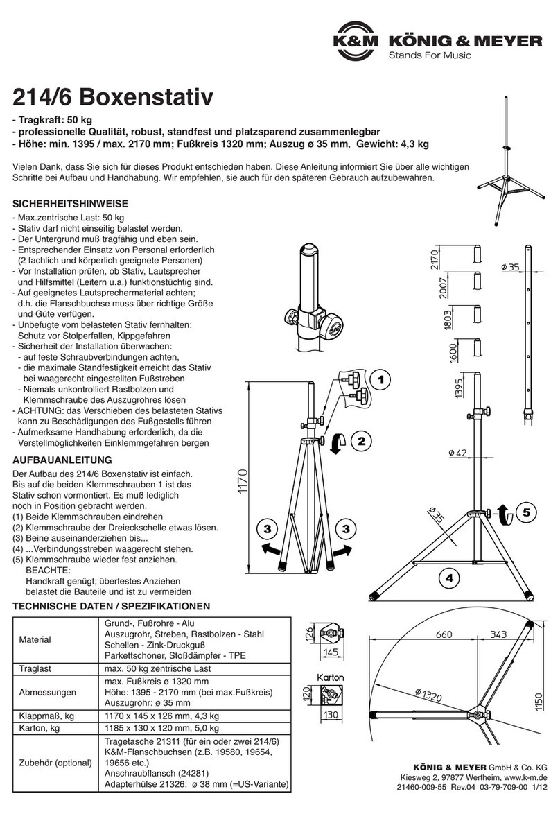
Konig & Meyer
Konig & Meyer 214/6 User manual
Konig & Meyer
Konig & Meyer 29680 Specification sheet
Konig & Meyer
Konig & Meyer 21450 User manual
Konig & Meyer
Konig & Meyer 21435 User manual
Konig & Meyer
Konig & Meyer 21435 User manual
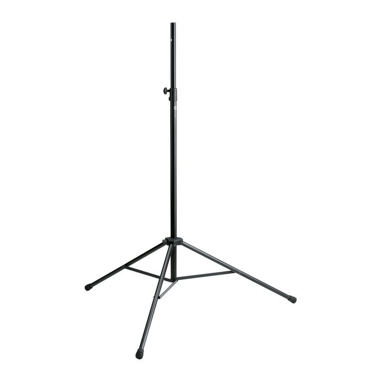
Konig & Meyer
Konig & Meyer 21420 User manual
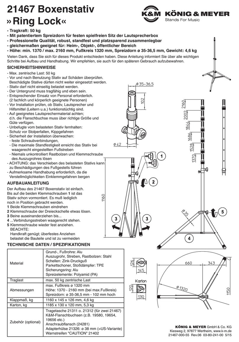
Konig & Meyer
Konig & Meyer Ring Lock 21467 User manual
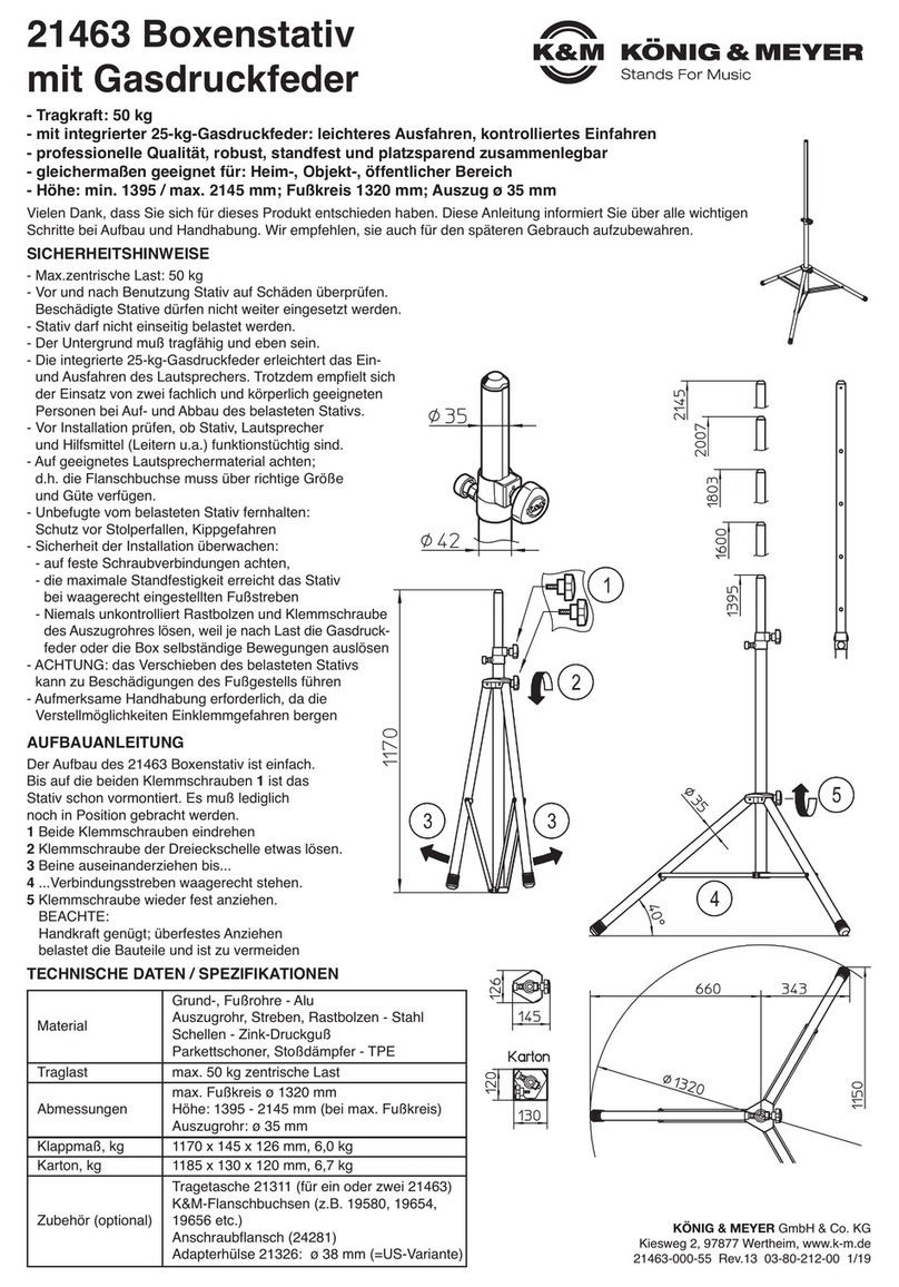
Konig & Meyer
Konig & Meyer 21463 User manual
Konig & Meyer
Konig & Meyer 24171 User manual
Konig & Meyer
Konig & Meyer Ring Lock 26737 User manual
