Konig & Meyer Ring Lock User manual

21440 Boxenstativ »Ring Lock«
- mit patentiertem Spreizdorn für festen, spielfreien Sitz der Box
- für Lautsprecher bis zu max. 50 kg
- robust, standfest und platzsparend zusammenlegbar
- Höhe: min. 1370-2100 mm, Fußkreisdurchmesser: 1260 mm, Spreizdorn: ø 35-37 mm, Gewicht: 5,2 kg
SICHERHEITSHINWEISE
ALLGEMEIN
- Stativ darf nicht einseitig belastet werden.
- Der Untergrund muss tragfähig und eben sein.
- Entsprechender Einsatz von Personal erforderlich.
- (2 fachlich und körperlich geeignete Personen)
- Vor Installation prüfen, ob Stativ, Lautsprecher
- und Hilfsmittel (Leitern u.a.) funktionstüchtig sind.
- Auf geeignetes Lautsprechermaterial achten;
- d.h. die Flanschbuchse muss über richtige Größe
- und Güte verfügen.
- Unbefugte vom belasteten Stativ fernhalten:
- Schutz vor Stolperfallen, Kippgefahren.
- Sicherheit der Installation überwachen:
- stets montierte Sicherungsschiene (S),
- feste Schraubverbindungen,
- maximal ausgezogene Füße (=waagerechte
- Fußstreben).
- ACHTUNG: das Verschieben des belasteten Stativs
- kann zu Beschädigungen des Fußgestells führen.
SPEZIELL
- Max. zentrische Last: 50 kg
- Die maximale Standfestigkeit erreicht das Stativ
- bei waagerecht eingestellten Fußstreben
- Niemals unkontrolliert Sicherungsschiene und
- Klemmschraube des Auszugrohres lösen
- Aufmerksame Handhabung erforderlich, da die
- Verstellmöglichkeiten Einklemmgefahren bergen
AUFBAUANLEITUNG
Der Aufbau des 21440 Boxenstativ ist einfach.
Alle Teile sind schon montiert, das Stativ
muss lediglich in Position gebracht werden.
(1) Klemmschraube der Dreieckschelle etwas lösen
(2) Beine auseinander ziehen bis...
(3) ...Verbindungsstreben waagerecht stehen
(4) Klemmschraube wieder fest anziehen.
(4) BEACHTE:
(4) Handkraft genügt; überfestes Anziehen
(4) belastet die Bauteile und ist zu vermeiden.
TECHNISCHE DATEN / SPEZIFIKATIONEN
Vielen Dank, dass Sie sich für dieses Produkt entschieden haben. Diese Anleitung informiert Sie über alle wichtigen Schritte bei Aufbau
und Handhabung. Wir empfehlen, sie auch für den späteren Gebrauch aufzubewahren.
KÖNIG & MEYER GmbH & Co. KG
Kiesweg 2, 97877 Wertheim, www.k-m.de
21440-000-55 Rev.01 03-79-704-00 12/08
Abmessungen
max. Fußkreisdurchmeser: 1260 mm
Höhe: 1370-2100 mm (bei max. Fußkreis)
Spreizdorn: ø 35-37 mm, 102 mm hoch
Packmaß, Gewicht: B x T x H: 120 x 110 x 1160 mm, 4,5 kg
Karton, Gewicht: B x T x H: 130 x 120 x 1185 mm, 5,2 kg
Karton H x B x T: 750 x 50 x 50 mm
Zubehör (optional)
Tragetasche 21311 (für ein oder zwei 21440)
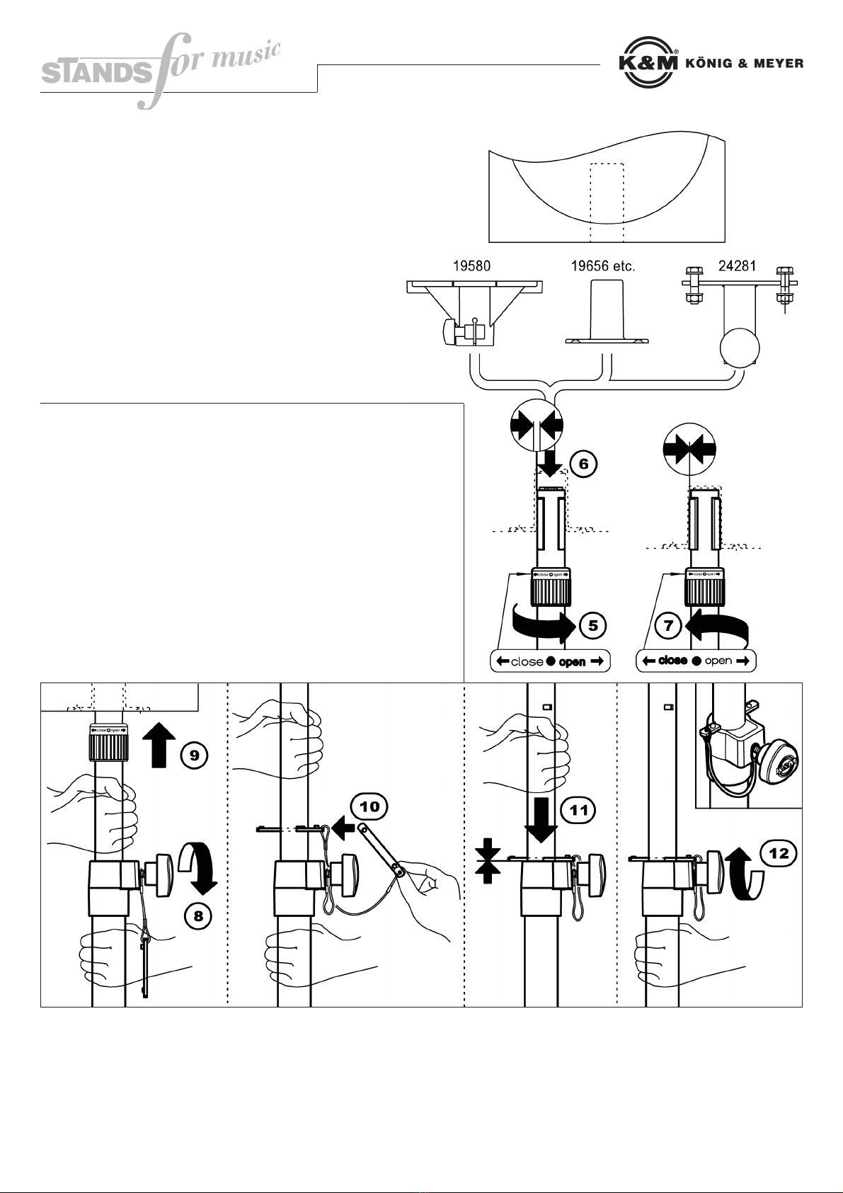
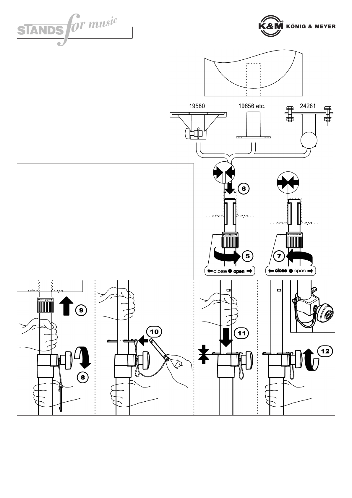
K&M-Flanschbuchsen (z.B. 19580, 19654, 19656 etc.)
Anschraubflansch (24281)
Adapterhülse 21326: ø 38 mm (=US-Variante)
Material
Grundrohr, Fußrohre - Alu
Auszugrohr, Fußstreben - Stahl
Schellen Fußgestell - Zink-Druckguß
Schelle Rohrkombination - Polyamid (PA)
Sicherungsring - Alu
Spreizelemente - Polyamid (PA)
Sicherungslasche, Kleinteile - Stahl
Parkettschoner, Stoßdämpfer -
Thermoplastischer Elastomer (TPE)
Traglast max. 50 kg zentrische Last
BENUTZERHINWEISE / FUNKTIONEN
ACHTUNG! Unterschätzen Sie nicht das Gewicht
des Lautsprechers (max. 50 kg); insbesondere das
belastete Auszugrohr stets mit Schiene (10) sichern, bzw.
mit festem Griff während der Höhenverstellung halten.
LAUTSPRECHER AM STATIV BEFESTIGEN
(5) Spreizdorn-Sicherungsring nach rechts drehen
(5) (Richtung OPEN), um den kleinsten Durchmesser
(5) einzustellen.
(6) Lautsprecher auf den Spreizdorn setzen.
(7) Sicherungsring jetzt nach links drehen
(7) (Richtung CLOSE) bis die Spreizbacken fest sitzen.
RICHTUNG DES LAUTSPRECHERS VERÄNDERN
Sicherungsring (5) öffnen und Box in die gewünschte
Richtung drehen.
Sicherungsring (7) wieder fest anziehen (Richtung CLOSE).
LAUTSPRECHER AUS- / EINFAHREN
ROLLENVERTEILUNG
Erste Person (E.P.): - hält Stativ; bedient Sicherungsschiene und
Erste Person (E.P.): - Klemmschraube;
Zweite Person (Z.P.): - bedient Auszugrohr und fährt den Lautsprecher
Zweite Person (Z.P.): - aus/ein
(8) E.P.: hält Grundrohr und löst Klemmschraube der Spannschelle
(9) Z.P.: fährt Auszug mit Lautsprecher in gewünschte Höhe
(10) E.P.: Schiene durch Schlitz schieben (Nocken OBEN)
(11) Z.P.: Auszugrohr vorsichtig ablassen bis Schiene auf Schelle
Z.P.: aufliegt
(12) E.P.: Klemmschraube festziehen (Handkraft genügt)
Das Einfahren des Lautsprechers erfolgt in umgekehrter Reihenfolge.
WICHTIG: sicherstellen, dass E.P. sofort die Klemmschraube (12)
anzieht, falls das Auszugrohr von der Z.P. nicht sicher gehalten werden
kann.
PRÜFEN, INSTANDHALTEN, REINIGEN
- Schonender Umgang mit dem Stativ erhält die Teleskopierbarkeit, die Tragkraft und die Sicherheit der Installation.
- Bei Wartungsarbeiten -stets im unbelasteten Zustand- auf evtl. Gefährdungen achten (Einklemmen, Anstoßen, Kippen).
- Zur Reinigung und Pflege am besten ein leicht feuchtes Tuch und ein nicht scheuerndes Reinigungsmittel benutzen.
FEHLERSUCHE (F) und BESEITIGUNG (B)
(F): Stativ wackelt (B): Bodenunebenheiten beseitigen / Fußgestell in max. Auslage bringen und Klemmschraube anziehen
(F): Auszugrohr wackelt bzw. fährt ein unter Last (B): Sicherungsschiene installieren, Klemmschraube anziehen
(F): Lautsprecher taumelt auf Spreizdorn (B): Sicherungsring nachziehen / Lautsprecherbuchse prüfen (max. ø 37 mm)
(F): Lautsprecher lässt sich schwer verdrehen (B): Box etwas anheben beim Verdrehen / Sicherungsring (5) noch etwas lockern

21440 Speaker Stand »Ring Lock«
- a patented expanding mandrel system provides a tight and firm fit for the speaker
- for speakers up to a maximum of 50 kg
- robust, stable and space saving and folding
- height: minimum 1370-2100 mm, footprint diameter: 1260 mm, expanding mandrel system: ø 35-37 mm, weight: 5.2 kg
SAFETY NOTICES
GENERAL
- Stand may not be loaded in a one-sided manner.
- The surface must be level and sustainable.
- Corresponding utilization of personnel required.
- (2 technically and physically suitable persons)
- Prior to installation, check if the stand, speaker and
- equipment (ladder among other things) are
- functional.
- Ensure the use of suitable speaker material;
- i.e. the flange adapter must be the right size and
- quality
- Keep unauthorized personnel from the stand:
- Protection against stumble trap, risk of tilting Monitor.
- The safety of the installation:
- all assembled safety rail (S),
- fixed screw connections,
- maximum extended legs (= horizontal struts).
- ATTENTION: the moving of the loaded stand
- can result in damaging the legs.
SPECIFICS
- Do not exceed the maximum central load: 50 kg
- The maximum sustainability is attained by the stand,
- if the struts are adjusted in a horizontal position
- Never loosen the security rail and the clamping screws
- of the adjustable rod in an uncontrolled manner
- Careful handling required, since the adjustment
- possibilities can lead to possible pinching
ASSEMBLY INSTRUCTIONS
The setup of the 21440 speaker stand is simple.
All parts are already assembled, the stand only
has to be put into position.
(1) Loosen the clamping screw of the triangular
(1) clamp/bracket slightly
(2) Extend the legs until...
(3) ...the connection struts are horizontal
(4) Re-tighten the lower clamping screw.
(4) OBSERVE: Manual strength is sufficient; avoid over
(4) tightening, it places undue stress on the components..
TECHNISCHE DATEN / SPEZIFIKATIONEN
Thank you very much for selecting this product. These instructions provide the information on all the important assembly and handling
steps required for assembly. We recommend that you store a copy of these instructions for future use.
KÖNIG & MEYER GmbH & Co. KG
Kiesweg 2, 97877 Wertheim, www.k-m.de
21440-000-55 Rev.01 03-79-704-00 12/08
Dimensions
max. footprint diameter: 1260 mm
height: 1370-2100 mm (maximum footprint)
expanding mandrel system: ø 35-37 mm, 102 mm height
Packaging, Weight: W x B x H: 120 x 110 x 1160 mm, 4.5 kg
Package, Weight: W x B x H: 130 x 120 x 1185 mm, 5.2 kg
Package H x W x B: 750 x 50 x 50 mm
Accessories
(optional)
carrying case 21311 (for one or two 21440)
K&M flange adapter (eg.: 19580, 19654, 19656 etc.)
screw-on adapter (24281)
Adapter sleeve 21326: ø 38 mm (=US-Variant)
Material
basic rod, leg rods - aluminum
expandable rod, leg struts - steel
clamps/brackets - zinc-die-cast
quick rod combination - polyamide (PA)
ring lock - aluminum
mandrel elements - Polyamide (PA)
security strap, small parts - steel
Parquet protector, shock absorber -
Thermoplastic Elastomer (TPE)
Load max. 50 kg central load
USER INFORMATION / FUNCTIONS
ATTENTION! Do not underestimate the weight of the
speaker (max. 50 kg); in particular secure the
loaded expandable rod with rail (10), or with fixed handle
during height adjustment.
AFFIX THE SPEAKER TO THE STAND
(5) Turn the expanding mandrel system - ring lock to the
(5) right (direction OPEN) to the smallest diameter.
(6) Place the speaker on the expanding mandrel system.
(7) Now turn the ring lock to the left
(7) (direction CLOSE) until the splints fit tightly.
ADJUST THE DIRECTION OF THE SPEAKER
Open ring lock (5) and adjust the speaker in the desired
direction.
Re-tighten the ring lock (7) (direction CLOSE).
EXTEND / RETRACT SPEAKER
ROLES
First person (F.P.): - holds the stand, operates the security rail and
First person (F.P.): - clamping screw;
Second person (S.P.): - operates the expandable rod and extends or
Second person (S.P.): retracts the speaker
(8) F.P.: hold the basic rod and loosens the clamping screw of the
(8) clamping bracket
(9) S.P.: extend the speaker to the desired height
(10) F.P.: place the rail through the slot (Pins UPPER)
(11) S.P.: lower the expandable rod carefully until the rail sets on the
S.P.: bracket
(12) F.P.: tighten the clamping screw (Manual strength is sufficient)
The retraction of the speaker takes place in the opposite order.
IMPORTANT: ensure that the F.P. immediately tightens the clamping screw
(12), in the event the expandable rod cannot be held securely byn the S.P..
INSPECTION, MAINTENANCE, CLEANING
- Careful handling of the stand maintains the ability to extend and retract the stand, the loadability and the safety of the installation.
- Look for possible dangers/risks (pinching, colision, tipping) during maintenance work. Maintenance is always to be performed when
-the system is not under strain.
- For cleaning and maintenance purposes it is best to utilize a damp cloth and a non-abrasive cleaning solvent.
ERROR IDENTIFICATION (E) and CORRECTION (C)
(E): Stand rocks (C): Remove surface unevenness/ Place legs in the maximum extended position and tighten the clamping screw
(E): Expandable rod rocks or retracts due to the load (C): Install the security rail, tighten the clamping screw
(E): Speaker teeters on the expanding mandrel system (C): Re-tighten the ring lock / check speaker mounting adapter (maximum ø 37 mm)
(F): Speaker is difficult to adjust (B): Lift the speaker up a bit during the adjustment. / Loosen ring lock (5) a little more.
This manual suits for next models
1
Table of contents
Languages:
Other Konig & Meyer Speakers manuals

Konig & Meyer
Konig & Meyer 21435 User manual

Konig & Meyer
Konig & Meyer Ring Lock User manual

Konig & Meyer
Konig & Meyer 29680 Specification sheet

Konig & Meyer
Konig & Meyer 21420 User manual

Konig & Meyer
Konig & Meyer 214/6 User manual

Konig & Meyer
Konig & Meyer 21450 User manual

Konig & Meyer
Konig & Meyer 21450 User manual

Konig & Meyer
Konig & Meyer Ring Lock 21467 User manual

Konig & Meyer
Konig & Meyer 21435 User manual

Konig & Meyer
Konig & Meyer Ring Lock 26737 User manual


