Konig & Meyer Ring Lock User manual

21476 Boxenstativ »Ring Lock«
BESTIMMUNGSGEMÄSSER GEBRAUCH:
- Dreibeinstativ mit Handauszug zur Aufnahme von PA-Lautsprechern,
-z.B. den Teufel ROCKSTER AIR
MERKMALE & FÄHIGKEITEN
- Mit patentiertem Spreizdorn für festen spielfreien Sitz der Lautsprecherbox
- Professionelle Qualität. robust, standfest und platzsparend zusammenlegbar
- Gleichermaßen geeignet für Proberaum, Studio, Bühne, Tour - und Partyraum
- Maximale Tragfähigkeit: 50 kg*
- Höhe 1420 - 2200 mm, Fußkreis ø 1150 mm, Spreizdorn ø 35-36,5 mm,
-Gewicht 6,2 kg
SICHERHEITSHINWEISE (Kurzfassung)
Vollständige Angaben siehe beigefügtes Blatt.
A. ALLGEMEIN
- Die maximale zentrische Tragfähigkeit beträgt 50 kg*
- Traglast ist eine passende PA mit Buchse ø 35 mm (z.B. Teufel ROCKSTER AIR)
- Auf geeigneten, d.h. ebenen und tragfähigen Untergrund achten
- Entsprechender Einsatz von geeignetem Personal erforderlich (fachlich u. körperlich)
- Die Sicherheit des Betriebes beruht u.a. auf der Beachtung dieser Bedienungsanleitung,
-insbesondere der hier unter A-Ggenannten Punkte.
B. HINWEIS auf „VORHERSEHBARE FEHLANWENDUNG"
- Grund- und Auszugrohrkombination muss stets senkrecht (nicht geneigt!) aufgestellt sein
- Stativ nicht einseitig belasten, da es die Standfestigkeit bzw. Tragfähigkeit verringert
- Das Verschieben des Stativs, vor allem unter Belastung, ist nicht erlaubt
- Stativ vor Nässe und Feuchtigkeit schützen
C. VOR DER BENUTZUNG
- Stativ einer Sichtprüfung unterziehen - beschädigte Stative dürfen nicht eingesetzt werden
D. AUFSTELLUNG DES STATIVS
- Für maximale Standfestigkeit, stellen Sie den größtmöglichen Fußkreisdurchmesser ein
- Klemmschrauben fest anziehen - jedoch ohne Werkzeugeinsatz. Handkraft genügt völlig
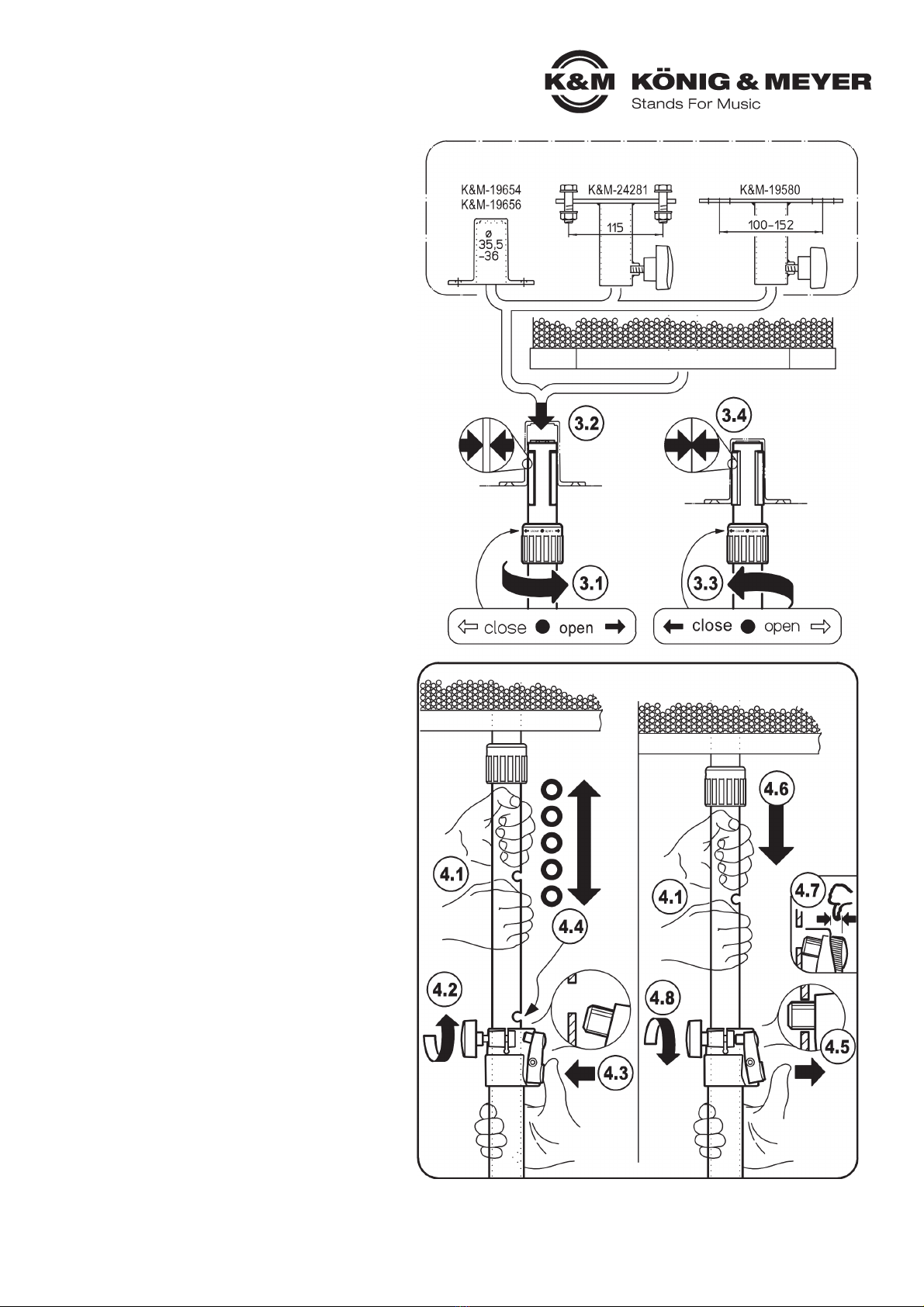
- Rastbolzen 4.5 zur Fixierung des Auszugrohres muss sich stets im Eingriff befinden
-- ausgenommen bei Höhenverstellung
E. AUS-/EINFAHREN DER TRAGLAST (siehe Kapitel 4)
- Diese Tätigkeiten grundsätzlich von mind. zwei geeigneten Personen durchführen lassen
- Die "Erste Person" hat das Auszugrohr mit Traglast fest und sicher zu halten, während die
-"Zweite Person" die Sicherungselemente Rastbolzen und Klemmschraube jederzeit einsetzen
-kann, z.B. wenn die "Erste Person" nicht in der Lage sein sollte Rohr und Traglast zu halten.
F. WÄHREND DER BENUTZUNG
- Niemals unkontrolliert Rastbolzen 4.3 und Klemmschraube 4.2 des Auszugrohres lösen
- BEHERRSCHUNG von SEITENKRÄFTEN (relevant wegen Kippgefährdung)
-Seitenkräfte sind unbedingt zu vermeiden. Sie treten auf bei:
-a. schräg stehendem Stativ
-b. außermittigem Schwerpunkt der Traglast
-c. externen Schocks (Stöße, Zerren am Stativ, Erschütterungen, Wind etc.)
G. NACH DER BENUTZUNG
- Traglast langsam und kontrolliert einfahren lassen (siehe oben - E)
- Sichtprüfung vornehmen (siehe oben - C)
- Stativ sorgsam zusammenlegen und geschützt verstauen
AUFSTELL- / GEBRAUCHSANLEITUNG
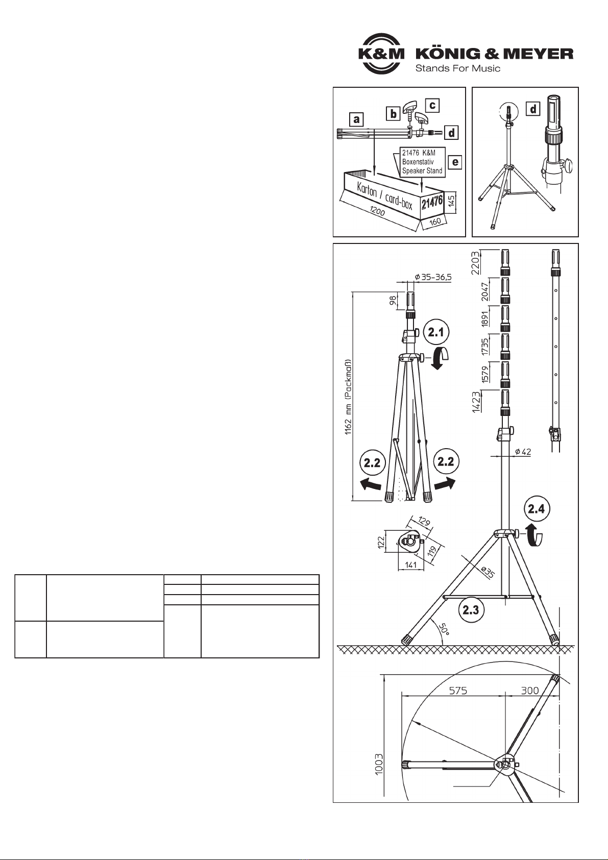
1. BESTANDTEILE
Nach dem Auspacken Sichtprüfung vornehmen, ob alle Teile vorhanden und - soweit erkennbar -
unbeschädigt sind:
aStativ, zusammengeklappt,
bKlemmschraube (M8 x 23 mm) der Dreieckschelle
cKlemmgriff (M8-Innengewinde) der Teleskop-Rastschelle
dAuszugrohr mit »Ring Lock«-Mechanismus
eGebrauchsanleitung
2. MONTAGE, AUFSTELLUNG, ABMESSUNGEN
Das 21476 Stativ ist werkseitig komplett vormontiert. Beim Aufstellen bitte vorgehen wie folgt:
2.1 Klemmschraube bder Dreieckschelle etwas lösen.
2.2 Beine möglichst gleichzeitig auseinanderziehen bis...
2.3 ...Verbindungsstreben waagerecht stehen (= maximaler Fußkreisdurchmesser)
2.4 Klemmschraube bwieder fest anziehen - Handkraft genügt völlig.
2.4 HINWEIS: Überfestes Anziehen ist zu vermeiden - es belastet die Bauteile.
TECHNISCHE DATEN
Vielen Dank, dass Sie sich für dieses Produkt entschieden haben. Bitte lesen und beachten
Sie sorgfältig diese Anleitung. Sie informiert Sie über alle wichtigen Schritte die für einen
sicheren Aufbau und Betrieb erforderlich sind. Wir empfehlen, sie auch für den späteren
Gebrauch aufzubewahren.
KÖNIG & MEYER GmbH & Co. KG
Kiesweg 2, 97877 Wertheim, www.k-m.de
21476-000-55 Rev.03 03-80-632-00 9/21
Material
Grund-, Fuß- Auszugrohr: Stahl
Streben, Schrauben, Nieten: Stahl
Spannring: Aluminium
Schellen, Griffe, Spreizbacken: PA
Parkettschoner, Dämpfer: TPE
Maße
max. Fußkreis: ø 1150 mm
Höhe: min.1420 - max. 2200 mm
Packmaß: 1162 x 120 x 130 mm
Nettogewicht: 6,2 kg
Traglast max. 50 kg*
Auszug Spreizdorn: ø 35-36,5 mm x 102 mm
Karton 1200 x 145 x 60 mm
Zubehör
(optional)
Tragetasche 21311, 21312
Flanschbuchsen (19654, 19656)
Anschraubflansch (19580, 24281)
Warnstreifen 21402
Ausgleichsadapter 21445
Adapterhülse 21326: ø 38 mm (US)
* Bei zentrischer Belastung, auf waagerechter Fläche und ohne Seitenkräfte (Wind, Stöße etc.)
2. MONTAGE, AUFSTELLUNG
2. und ABMESSUNGEN
1. BESTANDTEILE
Ansicht von oben
Fußkreisdurchmesser 1150
Kipplinie
Zentrum

FEHLERSUCHE (F) und BESEITIGUNG (B)
Siehe BEIBLATT
WARTUNG
Siehe BEIBLATT
TRAGLAST AUFBRINGEN und AUSFAHREN
WARNUNG!
Unterschätzen Sie nicht das Gewicht des Lautsprechers:
- Das Aufsetzen und Aus- bzw. Einfahren des Lautsprechers muss durch
-fachlich und körperlich geeignetes Personal erfolgen.
- Auszugrohr während der Höhenverstellung mit festem Griff halten 4.1
-und die gewünschte Endstellung stets mit dem Rastbolzen 4.5 sichern.
3. LAUTSPRECHER AM STATIV BEFESTIGEN
3.1 Spreizdorn-Spannmuffe nach rechts drehen (Richtung OPEN),
3.1 um den kleinsten Durchmesser einzustellen.
3.2 Lautsprecher auf den Spreizdorn setzen.
3.3 Spannmufffe jetzt nach links drehen (Richtung CLOSE) bis...
3.4 ...die Spreizbacken fest sitzen.
4. DAS AUS-/EINFAHREN DER TRAGLAST
Beteiligte:
ERSTE PERSON: (bei schweren Lasten ggf. mehrere Personen):
ERSTE PERSON: - bedient das Auszugrohr mit der Traglast 4.1, 4.4,4.6
ZWEITE PERSON: - bedient an der Spannschelle
ZWEITE PERSON: -a. die Klemmschraube 4.2, 4.8 und
ZWEITE PERSON: - b. den Rastbolzen 4.3, 4.5, 4.7
VORSICHT!
Sollte das belastete Auszugrohr von der ERSTEN PERSON nicht mehr
sicher gehalten werden können, so muss die ZWEITE PERSON:
a. sofort die Klemmschraube 4.8 anziehen,
b. ebenfalls sofort den Rastbolzen 4.5 loslassen, und sicherstellen,
b. dass dieser selbständig in die nächstliegende Bohrung einrastet.
AUSFAHREN DER TRAGLAST
ERSTE PERSON
4.1 hält das belastete Auszugrohr mit beiden Händen gut fest.
4.1 Dabei nicht über die Bohrungen greifen.
ZWEITE PERSON
4.2 lockert die Klemmschraube und hält diese fest und...
4.3 ...betätigt den Druckknopf bis der Rastbolzen nicht
4.3 mehr in das Auszugrohr eingreift
ERSTE PERSON
4.4 stemmt das Auszugrohr mitsamt der Traglast
4.4 in die ungefähr gewünschte Höhe;
4.4 BEACHTE:
4.4 zum einfachen Auffinden der entsprechenden Rastbohrung sollte
4.4 sich diese in jenem Moment kurz über der Spannschelle befinden
ZWEITE PERSON
4.5 lässt den Druckknopf los, so dass der Rastbolzen
4.5 selbständig ins Auszugrohr einrasten kann.
ERSTE PERSON
4.6 lässt das Auszugrohr langsam ab bis der Rastbolzen
4.6 nun ins vorgesehene Loch einrastet
ZWEITE PERSON
4.7 stellt sicher, dass Rastbolzen bis zum Anschlag
4.7 eingerastet ist (= kein Überstand erlaubt)
4.8 dreht die Klemmschraube fest
EINFAHREN DER TRAGLAST
ERSTE PERSON
4.1 hält mit beiden Händen das belastete Auszugrohr fest.
4.1 Dabei nicht über die Bohrungen greifen.
ZWEITE PERSON
4.2 lockert die Klemmschraube nur ganz wenig und...
4.3 ...betätigt den Druckknopf und hält ihn gedrückt
4.3 (der Rastbolzen ist entriegelt)
ERSTE PERSON
4.6 lässt das Auszugrohr langsam und kontrolliert ab
ZWEITE PERSON
4.8 dosiert die Klemmkraft der Schraube so, dass das Auszugrohr
4.8 aufgrund der Reibung in der Spannschelle schön langsam einfährt
4.8 - und nicht plötzlich und ungebremst
ERSTE PERSON
4.6 hält nach wie vor das Auszugrohr fest und sichert so das kontrollierte
4.6 Einfahren der Last ab. Dies entweder bis zur gewünschten Höhe
4.6 oder auch bis es komplett eingefahren ist.
ZWEITE PERSON
4.5 lässt den Druckknopf los, so dass der Rastbolzen von selbst
4.5 ins Auszugrohr einrasten kann
4.7 stellt sicher, dass Rastbolzen bis zum Anschlag eingerastet ist
4.7 (= kein Überstand erlaubt)
4.8 dreht die Klemmschraube fest
BENUTZERHINWEISE / FUNKTIONEN
Zubehör - Anwendungsbeispiele (nicht im Lieferumfang) - nur für Auszug ø 35 mm
lösen
entriegeln
festziehen
einrasten
lassen
AUS-/EINFAHREN DER TRAGLAST

VOLLSTÄNDIGE AUSFÜHRUNGEN der jeweiligen Kurzfassungen in der Gebrauchsanleitung
SICHERHEITSHINWEISE
Mit * gekennzeichnete Ziffern, z.B. *14, beziehen sich auf Hinweisnummern in der Grafik der Gebrauchsanleitung
A. ALLGEMEIN
- Die maximale zentrische Tragfähigkeit beträgt 50 kg
- Traglast ist eine passende PA mit Buchse ø 35 mm (z.B. Teufel ROCKSTER AIR)
- Auf geeigneten, d.h. ebenen und tragfähigen Untergrund achten.
-Die Füße dürfen nicht weggleiten oder einsinken - egal ob das Stativ belastet ist oder nicht.
- Bei unebenem Untergrund (oder Stufen) muss durch geeignete Maßnahmen die vertikale Stellung des Tragrohres sichergestellt werden:
-z.B. durch Einsatz des K&M-Ausgleichsadapters 21445 (optional erhältlich)
- Ausreichend Personal einsetzen (ggf. zwei oder mehr fachlich u. körperlich geeignete Personen)
- Unbefugte Personen vom belasteten Stativ fern- und Sicherheitsabstände einhalten.
- Bei Nichteinhaltung der Sicherheitsabstände besteht Stolpergefahr. Diese kann minimiert werden durch den Einsatz des optisch auffälligen
-Warnstreifens 21402 (optional erhältlich)
- Aufmerksame Handhabung erforderlich, da die Verstellmöglichkeiten naturgemäß Einklemmgefahren bergen
- Die Sicherheit des Betriebes beruht u.a. auf der Beachtung dieser Bedienungsanleitung,insbesondere der hier unter A-Ggenannten Punkte.
B. HINWEIS auf VORHERSEHBAREN FEHLGEBRAUCH
- Die Grund- und Auszugrohrkombination darf nicht geneigt, sondern muss vielmehr senkrecht aufgestellt sein. Mögliche Ursachen für
-Schiefstand sind: ungeeigneter Untergrund, einseitige Belastung, defektes Stativ.
- Stativ nicht einseitig belasten (außermittige Belastung beeinträchtigt die Standfestigkeit der Installation bzw. mindert die max. Tragfähigkeit).
- ACHTUNG: das Verschieben des Stativs, v.a. unter Belastung, ist nicht erlaubt, da dies zu erheblichen Gefährdungen führen kann
-(Kippgefahr, Schäden an Bauteilen).
- Stativ vor Nässe und Feuchtigkeit schützen.
C. VOR DER BENUTZUNG
- Zunächst Sichtprüfung vornehmen, ob das Stativ vollständig und soweit erkennbar unbeschädigt ist. Beschädigte Stative dürfen nicht ein-
-gesetzt werden - bzw. erst nach einer qualifizierten Reparatur.
- Traglasten und Hilfsmittel (z.B. Leitern) sind ebenfalls auf Tauglichkeit zu prüfen.
D. AUFSTELLUNG DES STATIVS
- Prüfen Sie die Funktion und Gängigkeit des Stativs und seiner Bauteile zunächst im unbelasteten Zustand
- Beachten Sie die Angaben im Kapitel 2. AUFSTELLANLEITUNG
- Für maximale Standfestigkeit, stellen Sie den größtmöglichen Fußkreisdurchmesser ein.
-Dieser Zustand ist gegeben bei waagerechter Position der Fußstreben.
-WARNUNG: unvollständig aufgeklappte Fußstreben mögen Platz sparen, gefährden aber massiv die Standsicherheit.
- Klemmschrauben *2.4 / *4.8 fest anziehen - jedoch ohne Einsatz von Werkzeugen.
-Handkraft genügt völlig, zumal überfestes Anziehen die Bauteile belastet.
- Nach abgeschlossener Höhenverstellung muss sich der Rastbolzen *4.5 stets im Eingriff befinden und die Klemmschraube *4.8
-angezogen sein.
E. AUS-/EINFAHREN DER TRAGLAST (siehe Kapitel 4)
- Diese Tätigkeiten grundsätzlich von mind. zwei geeigneten Personen durchführen lassen
- Die "Erste Person" hat das Auszugrohr mit Traglast fest und sicher zu halten, während die "Zweite Person" die Sicherungselemente Rast-
-bolzen und Klemmschraube jederzeit einsetzen kann, z.B. wenn die "Erste Person" nicht in der Lage sein sollte Rohr und Traglast zu halten.
F. WÄHREND DER BENUTZUNG
- Niemals unkontrolliert Rastbolzen *4.3 und Klemmschraube *4.2 des Auszugrohres lösen. Vielmehr muss die in Kapitel E. (s.o.) beschriebene
-Vorgehensweise zwingend beachtet werden.
- BEHERRSCHUNG von SEITENKRÄFTEN (relevant wegen der KIPPGEFÄHRDUNG).
-Seitenkräfte sind unbedingt zu vermeiden. Sie treten auf bei:
-a. schräg stehendem Stativ:
-a. - Maßnahmen: für ebenen Untergrund sorgen, Ausgleichsadapter K&M 21445 verwenden
-b. außermittigem Schwerpunkt der Traglast:
-b. - Maßnahmen: nur marginale Abweichung zulassen
3. c. externen Schocks (Stöße, Zerren am Stativ, Erschütterungen, Wind etc.):
-c. - Maßnahmen: für Einhaltung der Sicherheitsabstände sorgen und Unbefugte fernhalten
-Falls diese Anforderungen nicht eingehalten werden können, sind durch den Aufsteller weitere Maßnahmen zu treffen, um die Sicherheit der
-Installation zu gewährleisten. Beispiele:
-- Stativ mit Seilen abspannen, -Traglast verringern, -Stativhöhe reduzieren, -Position wechseln.
G. NACH DER BENUTZUNG
- Traglast langsam und kontrolliert einfahren lassen. Bitte beachten Sie die Kapitel E. (s.o.) sowie die in Kapitel 4 der AUFSTELLANLEITUNG
-beschriebenen Vorgehensweise.
- Erneut Sichtprüfung vornehmen, ob das Stativ vollständig und soweit erkennbar unbeschädigt ist. Schadhafte Stative müssen vor weiterer
-Benutzung einer qualifizierten Reparatur unterzogen werden.
- Erst die Traglast entfernen - dann das Stativ sorgsam zusammenlegen und geschützt verstauen.
BEIBLATT
der Gebrauchsanleitung
21476-000-55 Boxenstativ »Ring Lock«

VOLLSTÄNDIGE AUSFÜHRUNGEN der jeweiligen Kurzfassungen in der Gebrauchsanleitung
WARTUNG:
PRÜFEN, INSTANDHALTEN, REINIGEN
ZIEL
der Wartung ist es, dem Stativ die leichte Gängigkeit, die Tragkraft und die Sicherheit der Installation dauerhaft zu erhalten.
Erreicht wird dies durch:
a. schonenden Umgang,
b. Beseitigung von Schmutz, Feuchtigkeit, Korrosion
c. Austausch oder Reparatur schadhafter Teile - ohne erforderliche Spezialkenntnisse
WARTUNGSPERSONAL
In Anlehnung an DGUV Grundsatz 315-390 (ehemals BGG/GUV-912 Kap.4-Qualifikationen)
benötigt das Wartungspersonal mindestens die Qualifikation einer Unterwiesenen Person.
Diese kann: - sachgerecht auf- und abbauen, - Sicht- und Funktionsprüfungen durchführen,
Diese kann: - äußere Schäden und Verschleiß, betriebssicheren Zustand und die Funktionsfähigkeit der Schutzeinrichtungen erkennen.
MASSNAHMEN
- SICHTPRÜFUNG vor und erneut nach der Benutzung vornehmen. Ist das Stativ:
-- funktionstüchtig (gängig, nicht ausgeleiert, senkrecht stehend, Schrauben u. Rastbolzen intakt),
-- vollständig (Klemmgriffe, Parkettschoner, Nieten) und - soweit erkennbar:
-- unbeschädigt (deformierte Rohre und Streben, abgeplatzte Schellen, ausgeleierte Nieten)
-Beschädigte Stative dürfen nicht eingesetzt werden bzw. erst nach einer qualifizierten Reparatur.
- Der Austausch loser Bauteile (z.B. Parkettschoner, Klemmschrauben) kann vor Ort erfolgen.
-Reparaturen bzw. der Ersatz unlösbar verbundener Teile (Rohre, Schellen, Nieten, Streben)
-muss durch qualifiziertes Fachpersonal oder im Hause des Herstellers (K&M) erfolgen.
- Pflege und Instandhaltungsarbeiten haben stets im unbelasteten Zustand stattzufinden
- Mögliche Gefährdungen bei Wartungsarbeiten sind Quetschungen beim Einklappen der Füße.
-Um diese zu vermeiden ist eine entsprechend aufmerksame Handhabung erforderlich.
-Ggf. Schutzhandschuhe benutzen.
- Zur Reinigung ein leicht feuchtes Tuch und ein nicht scheuerndes Reinigungsmittel benutzen
- Anderweitige Maßnahmen wie z.B. periodische Schmierung etc. sind nicht erforderlich.
FEHLERSUCHE (F) und BESEITIGUNG (B)
F: STATIV WACKELT ODER STEHT SCHIEF
F: B: Bei mangelnder Eignung des Bodens (instabil, uneben) diese
F: B: zunächst wiederherstellen oder den Standort wechseln.
F: B: Schrägen Untergrund ggf. durch Ausgleichadapter 21445 kompensieren
F: B: Fehlende oder beschädigte Parkettschoner durch Originalteile ersetzen
F: B: Füße maximal weit auseinanderziehen (=waagerechte Streben *2.3)
F: B: Außermittige Belastung effektiv reduzieren
F: B: Negative äußere Einflüsse (Wind, Erschütterungen) abstellen
F: B: oder durch zusätzliche Maßnahmen kompensieren (Seilspanner)
F: AUSZUGROHR WACKELT ODER FÄHRT EIN UNTER LAST
F: B: Sicherstellen, dass der Rastbolzen *4.5 in die Bohrung eintaucht
F: B: Klemmschrauben *2.4, 4.8 anziehen
F: LAUTSPRECHER TAUMELT AUF SPREIZDORN
F: B: Sicherungsring *3.3 nachziehen
F: B: Lautsprecherbuchse prüfen (max. ø 36 mm)
F: B: Bei US-Lautsprecherbuchsen (ø 38 mm) immer Adapterhülse 21326 verwenden
F: LAUTSPRECHER LÄSST SICH SCHWER DREHEN
F: B: Lautsprecher etwas anheben beim Verdrehen
F: B: Sicherungsring noch etwas lockern *3.1
BEIBLATT
der Gebrauchsanleitung
21476-000-55 Boxenstativ »Ring Lock«
KÖNIG & MEYER GmbH & Co. KG
Kiesweg 2, 97877 Wertheim, www.k-m.de
03-80-633-00 9/21

SAFETY INSTRUCTIONS (summary)
Please see the attached sheet for precise details.
A. GENERAL
- The maximum centric load-bearing capacity adds up to 50 kg*
- Load capacity is a suitable PA with bushing ø 35 mm (e.g. Teufel ROCKSTER AIR)
- Ensure that the floor is suitable, i.e. level and loadbearing
- Works should be carried out by competent staff (technical and physical)
- The safety of operation is based, among other things, on the observance of these operating
-instructions, especially the points mentioned here under A-G.
B. NOTICE of "FORESEEABLE MISAPPLICATION"
- Base and extension tube combination must always be installed vertically (not inclined!)
- Do not load the stand on one side, as this reduces the stability or load-bearing capacity
- It is not allowed to shift the stand, especially under load
- Protect the stand from moisture and humidity
C. BEFORE USE
- Visually inspect the stand - do not use damaged stands
D. ASSEMBLING THE STAND
- For maximum stability, set the largest possible root diameter
- Tighten the clamping screws firmly, but without using any tools. Hand tight is completely sufficient
- The locking bolt 4.5 for fixing the extension tube must always be engaged
-- except when adjusting the height
E. EXTENDING/RETRACTING THE LOAD (see chapter 4)
- These activities must always be carried out by at least two suitable persons
- The "first person" has to hold the extension tube with bearing load firmly and securely, while the
-"second person" can use the securing elements locking bolt and clamping screw at any time.
-e.g. if the "first person" is not able to hold the tube and the load.
F. DURING USE - Safety during operation is based on:
- Never loosen locking bolt 4.3 and clamping screw 4.2 of the extension tube in an uncontrolled
-manner
- CONTROL of LATERAL FORCES (relevant due to danger of tipping)
-Lateral forces must be avoided. These occur when:
-a. the stand is inclined
-b. the load balance is exocentric
-c. external shocks such as kicks, pulling on the stand, vibrations, wind, etc. are suffered)
G. AFTER USE
- Allow the load to retract slowly and in a controlled manner (see above - E)
- Carry out visual inspection (see above - C)
- Carefully fold up the stand and stow it away in a protected place
INSTALLATION - / USER INSTRUCTIONS
1. COMPONENTS
After unpacking, visually inspect whether all parts are present and - if identifiable - whether they
are in order:
aStand, folded,
bClamping screw (M8 x 23 mm) for triangular clamp
cClamping handle (M8 internal thread) of the telescopic bolt clamp
dExtension tube with »Ring Lock« mechanism
eInstruction manual
2. ASSEMBLY, DIMENSIONS
The 21471 stand is completely pre-assembled ex factory. For installation proceed as follows:
2.1 Loosen slightly the clamping screw bof the triangular clamp.
2.2 Preferably, pull the legs apart simultaneously until...
2.3 ...the connecting struts are horizontal (= maximum root diameter)
2.4 Tighten clamping screw bagain – manual force is sufficient.
2.4 NOTE: Avoid overtightening - it strains the components.
TECHNICAL DATA
Thank you for choosing this product. Please read and follow carefully the instructions. They
inform you about all important steps, that are required for a safe assembly and operation.
Please keep the instructions for future reference.
Material
Base, foot, extension tubes: Steel
Struts, screws, rivets: Steel
Tension ring: Aluminum
Clamps, handles, mandrel elements: PA
Parquet protectors, dampener: TPE
Dimen-
sions
Max. base circle: ø 1150 mm
Height: min. 1420 - max. 2200 mm
Packing size: 1162 x 120 x 130 mm
Net weight: 6.2 kg
Load max. 50 kg*
Pull-out expanding mandrel syst.: ø 35-36,5
Box 1200 x 145 x 60 mm
Accessories
(optional)
Carrying case 21311
Flange adapter (19654, 19656)
Mounting adapter (19580, 24281)
Warning strip 21402
Leveling leg 21445
Adapter Sleeve 21326: ø 38 mm
* With centric loading, on a horizontal surface and without lateral forces (wind, shocks etc.)
2. ASSEMBLY, DIMENSIONS
Top view
Root circle diameter 1150
Tipping line
Centre
1. COMPONENTS
21476 Speaker stand »Ring Lock«
INTENDED USE :
- Stand with a manually adjustable extension for PA speakers,
-e.g. the Teufel ROCKSTER AIR
FEATURES & CAPABILITIES
- A patented expanding mandrel system provides a tight an firm fit for the speaker
- Professional quality. sturdy, stable and foldable to save space
- Suitable for rehearsal room, studio, stage, tour - and party room
- Maximum load-bearing capacity: 50 kg*
- Height 1420 - 2200 mm, base circle ø 1150 mm,
-expanding mandrel system: ø 35-36.5 mm weight 6.2 kg
KÖNIG & MEYER GmbH & Co. KG
Kiesweg 2, 97877 Wertheim, www.k-m.de
21476-000-55 Rev.03 03-80-632-00 9/21

ATTACHING and EXTENDING THE LOAD
WARNING!
Do not underestimate the weight of the speaker:
- When placing the speaker and extending or retracting the tube, be sure
-to employ technically and physically suitable personnel.
- Hold the extension tube with a firm grip during height adjustment 4.1
-and always secure the chosen final position with the locking bolt 4.5.
3. ATTACHING THE SPEAKER TO THE STAND
3.1 Turn expanding mandrel clamping sleeve to the right (direction
3.1OPEN), to set the smallest diameter.
3.2 Place the speaker on the expanding mandrel.
3.3 Now turn the clamping sleeve to the left (direction CLOSE) until...
3.4 ...the expanding mandrels fit firmly.
4. EXTENDING/RETRACTING THE LOAD
Involved parties:
FIRST PERSON: (in case of heavy loads, several persons if necessary):
FIRST PERSON: - operates the extension tube with the load 4.1, 4.4,4.6
SECOND PERSON: - attends to the clamp
SECOND PERSON: -a. the clamping screw 4.2, 4.8 and
SECOND PERSON: - b. the locking bolt 4.3, 4.5, 4.7
ATTENTION!
If FIRST PERSON can no longer hold securely the loaded extension
tube, then the SECOND PERSON should:
a. immediately tighten the clamping screw 4.8,
b. releases the locking bolt 4.5 and ensure that the bolt engages
b. automatically in the nearest borehole.
EXTENDING THE LOAD
FIRST PERSON
4.1 holds the loaded extension tube tightly with both hands.
4.1 Does not cover the boreholes.
SECOND PERSON
4.2 loosens the clamping screw and holds it and...
4.3 ...then presses the push button until the locking bolt
4.3 no longer engaged in the extension tube
FIRST PERSON
4.4 lifts the extension tube together with the load
4.4 into the approximately chosen height;
4.4 NOTE:
4.4 In order to find the chosen borehole easily, the bore should find itself
4.4 in this very moment just above the clamp
SECOND PERSON
4.5 releases the push button, so that the locking bolt
4.5 automatically snaps into the extension tube.
FIRST PERSON
4.6 lowers the extension tube slowly until the locking bolt
4.6 engages in the intended hole
SECOND PERSON
4.7 ensures that the locking bolt is engaged as far as it goes
4.7 (= no protrusion is allowed)
4.8 tightens the clamping screw
RETRACTING THE LOAD
FIRST PERSON
4.1 holds the loaded extension tube with both hands,
4.1 without covering the boreholes.
SECOND PERSON
4.2 loosens slightly the clamping screw and...
4.3 ...pushes the button and holds it
4.3 (the locking bolt is unlocked)
FIRST PERSON
4.6 lowers the extension tube slowly and controlled
SECOND PERSON
4.8 measures the clamp force of the screw so that the extension tube,
4.8 due to the friction in the clamp, retracts slowly and not suddenly
4.8 and uncontrolled
FIRST PERSON
4.6 whilst still holding the extension tube tightly, to ensure the controlled
4.6 retracting of the load. This needs to be carried out until the desired
4.6 height is reached or until the tube is completely retracted.
SECOND PERSON
4.5 releases the push button, so that the latching pin will automatically
4.5 snap into the extension tube
4.7 ensures that locking bolts engaged as far as it will go
4.7(= no protrusion allowed)
4.8 tightens the clamping screw
USER INSTRUCTIONS / FUNCTIONS
See the ATTACHED SHEET
FAULT-FINDING (F) and REPAIR (R)
See the ATTACHED SHEET
MAINTENANCE
Accessories - Application examples (not included) - only for extension ø 35 mm
unscrew
unlock
tighten
snap in
EXTENDING / RETRACTING THE LOAD

SUPPLEMENTAL SHEET
to instruction manual
21476-000-55 Speaker stand »Ring Lock«
COMPLETE VERSION of the relevant instruction summary
SAFETY INSTRUCTIONS
Numbers marked with *, e.g. *14, refer to reference numbers in the diagram of the instruction manual
A. GENERAL
- The maximum centric load-bearing capacity adds up to 50 kg*
- Load capacity is a suitable PA with bushing ø 35 mm (e.g. Teufel ROCKSTER AIR)
- Make sure that the floor is suitable, i.e. level and loadbearing. The foot of the stand should not slide or sink, regardless if it is loaded or not.
- If the floor is uneven (or steps), suitable measures must be taken to ensure vertical position of the support tube,
-e.g. by using the K&M compensation adapter 21445 (optionally available).
- Use sufficient personnel (if necessary two or more technically and physically suitable persons).
- Unauthorized persons must keep and maintain distance to the loaded stand.
- There is risk of tripping, if the safety distances are not observed. The danger can be minimized by using the eye-catching
-warning strip 21402 (optionally available).
- Careful handling is required, as the adjustment possibilities hide the risk of entrapment.
- The safety of operation is based, among other things, on the observance of these operating instructions, especially the points mentioned here
-under A-G.
B. NOTICE of "FORESEEABLE MISAPPLICATION"
- The mounting position of the base/extension tube combination should be vertical and not inclined. Possible causes for misalignment are:
-unsuitable floors, one-sided load, defective stand.
- Do not load the stand on one side (eccentric loading impairs stability of the installation respectively reduces the max. load-bearing capacity).
- ATTENTION: It is not allowed to shift the stand, especially under load, as this may lead to severe hazards
-(tip over hazard, damage to components).
- Protect the stand from moisture and humidity.
C. BEFORE USE
- First of all, visually check whether the stand is complete and, if so, whether it is all right. Damaged stands must not be used - or only
-after qualified repair.
- Loads and aids (e.g. ladders) must also be checked for suitability.
D. SETTING UP THE STAND
- First check the function and movability of the stand and its components in unloaded condition.
- Observe the information as mentioned in the chapter 2. ASSEMBLY INSTRUCTIONS.
- For maximum stability set the largest possible root diameter. This condition is given when the position of the bracing is horizontal.
-WARNING: A bracing that is not completely opened may save space but jeopardises severely the stability.
- Tighten the clamping screws *2.4 / *4.8 without using tools. Manual force is sufficient, especially since overtightening puts a strain on the
-components.
- When the height adjustment is completed, the locking bolt *4.5 should always be engaged and the clamping screw *4.8 should be tightened.
E. EXTENDING/RETRACTING THE LOAD (see chapter 4)
- These activities must always be carried out by at least two suitable persons
- The "first person" has to hold the extension tube with bearing load firmly and securely, while the "second person" can use the securing
-elements locking bolt and clamping screw at any time, e.g. if the "first person" is not able to hold the tube and the load.
F. DURING USE
- Never loosen uncontrolled the locking pin *4.3 and the clamping screw *4.2 of the extension tube. Rather, the procedure described in
-Chapter E. (see above) must be followed.
- CONTROL OF LATERAL FORCES (due to tipping hazard).
-Lateral forces must be avoided at all costs. They occur when:
-a. the stand is inclined:
-a. - measures: ensure a level flooring, use K&M 21445 compensation adapter
-b. eccentric balance of the load:
-b. - measures: allow only marginal deviation
-c. external shocks (jolts, pulling on the stand, vibrations, wind, etc.):
-c. - measures: ensure that the safety distances are observed and keep out unauthorized persons
-If these requirements cannot be met, the installer must provide further measures to ensure the safety of the installation.
-Examples:
-- stabilize the stand with ropes, reduce load and height, change position.
G. AFTER USE
- Retract the load slowly and in a controlled manner. Please observe chapter E. (see above) and the procedure described in chapter 4 of the
-ASSEMBLY INSTRUCTIONS.
- Perform another visual inspection to ensure that the stand is complete and, as far as can be seen, in good working order. Damaged stands
-must be subject to qualified repair before further use.
- First remove the speaker, then fold up the stand carefully and store it in a safe place.

MAINTENANCE:
CHECKING, MAINTENANCE, CLEANING
OBJECTIVE
of maintenance is to maintain the smooth mobility, load capacity and safety of the stand over a longer period of time. This is achieved by:
a. careful handling,
b. removing dirt, moisture, corrosion,
c. replacement or repair of defective parts - without any special knowledge
MAINTENANCE STAFF
According to DGUV (German general public accident insurance) standards 315-390 (former BGG/GUV-912 chap. 4 Qualifications)
maintenance personnel should have at least the qualification of an instructed person.
This person can: - detect external damage and wear, - carry out visual and functional checks,
This person can : - recognize safe operating condition and the functionality of the protective devices.
MEASURES
- Perform a visual inspection before and again after use. Is the stand:
-- functional (workable, not worn out, vertical standing, screws and locking bolts are intact),
-- complete (clamping handles, parquet protectors, rivets):
-- as far as visible undamaged (deformed tubes and struts, chipped off clamps, worn out rivets)
-Damaged stands must not be used or only after a qualified repair.
- Loose components (e.g. parquet protectors, clamping screws) can be replaced on site.
-Repairs or the replacement of inseparably connected parts (tubes, clamps, rivets, struts)
-must be carried out by qualified local personnel or at the manufacturer's premises (K&M).
- Care and maintenance work must always be carried out in an unloaded condition
- Possible hazards during maintenance work are crushing when folding the tubes.
-In order to avoid this, it is necessary to handle them with care.
-Use protective gloves if necessary.
- Use a slightly damp cloth and a non-abrasive cleaning agent for cleaning
- Other measures such as periodic lubrication, etc. are not necessary.
FAULT-FINDING (F) and REPAIR (R)
F: STAND WOBBLES OR IS CROOKED
F: R: If the floor is not suitable (unstable, uneven), restore or change location
F: R: If necessary, compensate sloping ground by using leveling leg 21445
F: R: Replace missing or damaged parquet protectors with original parts
F: R: Pull feet apart as far as possible (= horizontal struts *2.3)
F: R: Reduce eccentric load effectively
F: R: Stop negative external influences (wind, vibrations)
F: R: or compensate them by additional measures (rope stretching)
F: EXTENSION TUBE WOBBLES OR RETRACTS UNDER LOAD
F: R: Ensure that the locking bolt *4.5 is engaged
F: R: Tighten the clamping screws *2.4, 4.8
F: SPEAKER TEETERS ON THE EXPANDING MANDREL SYSTEM
F: R: Re-tighten the ring lock *3.3
F: R: Check speaker bushes (max. ø 36 mm)
F: B: For US speaker bushes (ø 38 mm) always use adapter sleeve 21326
F: SPEAKER IS DIFFICULT TO ADJUST
F: R: Lift the speaker up a bit during the adjustment
F: R: Loosen ring lock *3.1 a little more
SUPPLEMENTAL SHEET
to instruction manual
21476-000-55 Speaker stand »Ring Lock«
COMPLETE VERSION of the relevant instruction summary
KÖNIG & MEYER GmbH & Co. KG
Kiesweg 2, 97877 Wertheim, www.k-m.de
03-80-633-00 9/21
This manual suits for next models
1
Table of contents
Languages:
Other Konig & Meyer Speakers manuals

Konig & Meyer
Konig & Meyer 26750 User manual

Konig & Meyer
Konig & Meyer 21435 User manual

Konig & Meyer
Konig & Meyer Ring Lock 21467 User manual

Konig & Meyer
Konig & Meyer 21450 User manual

Konig & Meyer
Konig & Meyer 21435 User manual

Konig & Meyer
Konig & Meyer 24171 User manual

Konig & Meyer
Konig & Meyer 29680 Specification sheet

Konig & Meyer
Konig & Meyer 21450 User manual

Konig & Meyer
Konig & Meyer 21420 User manual

Konig & Meyer
Konig & Meyer Ring Lock 26737 User manual