Kopp 2931.1302.9 User manual

Bedienungsanleitung (2-4)
Instruction Manual (5-8)
Bedieningshandleiding (9-12)
Mode d‘emploi (13-16)
Istruzioni sull‘uso (17-20)
Instrucciones de manejo (21-24)
Funk Magnetsensor
Radio magnetic sensor
Radio-magneetsensor
Capteur magnétique radio
Radiosensore magnetico
Radiosensor magnético
Artikel-Nr. 2931.1302.9
Stand Juni 2008 - ID-Nr.: 058 609 010
Heinrich Kopp GmbH
Alzenauer Str. 68
63796 Kahl
www.heinrich-kopp.de
www.free-control.com
(25-26)
�

2
Bedienungsanleitung bitte sorgfältig durchlesen!
Eine zuverlässige Frühwarnung und Schutz vor
Einbruch ist nur gegeben, wenn dieser Funk Magnet-
sensor in Einklang mit den folgenden Anweisungen
verwendet wird.
Anwendung
Überwachung von Türen und Fenstern. Erkennt das
Öffnen oder Schließen von Türen und Fenstern.
Überwachung von Gegenständen gegen unberech-
tigtes Entfernen.
Montage
Geeigneten Montageort wählen. Bohrschablone vor-
handen. Kunststoffunterteil für Höhenausgleich .
Vor endgültiger Montage bitte prüfen, ob der vorge-
sehene Empfänger das Funksignal des Magnetkon-
takts sicher empfängt. Gegebenenfalls Position des
Empfängers oder des Magnetsensors ändern.
Mitte des Magneten muss mit der Pfeilposition auf dem
Gehäuse des Funk Magnetsensors übereinstimmen .
Hinweis: Nicht auf oder in der Nähe von Metall-
flächen (z.B. Scharniere, Beschläge, Rahmen)
montieren.
Spannungsversorgung
3 V Lithiumbatterie CR 2450.
Batterielebensdauer bis zu 2,5 Jahre.
LED blinkt 1x beim Einlegen der Batterie .
Richtige Batteriepolung beachten.
Batteriekapazität wird überwacht.
Empfehlung: Batterietausch alle 2 Jahre
Sabotagekontakt
Zum einwandfreien Betrieb Gehäusedeckel richtig
aufsetzen = Sabotagekontakt geschlossen.
Beim Sabotageversuch wird Sabotagemeldung
gesendet.
Externer Kontakt
Zusätzlicher Kontakt ist anschließbar .
Dies kann ein zusätzlicher potentialfreier Magnet-
kontakt, Reedkontakt oder anderer Kontakt sein.
Elektronik erkennt zusätzlichen Kontakt automatisch,
nachdem dieser einmal geschlossen wurde.
Funk Magnetsensor und externer Kontakt arbeiten
gleichwertig / parallel.
Ohne externen Kontakt:
Anschlussklemmen können offen bleiben .
Drahtbrücke nicht notwendig .
Betriebsanzeige
LED blinkt 1x beim Einlegen der Batterie und
geht dann aus:
• Batterie voll
• Gerät betriebsbereit
LED blitzt 1x pro Minute:
• Batterie schwach
• Alarmerkennung noch möglich
• Signalaussendung noch möglich
LED blinkt schnell:
• Batterie fast leer
• Alarmerkennung nicht mehr möglich
• Signalaussendung nicht mehr möglich
Die Konformitätserklärung kann unter folgender Adresse gefunden werden:
Heinrich Kopp GmbH • Alzenauer Straße 68 • 63796 Kahl am Main oder www.free-control.com

3
Funktionseinstellung
Funk Magnetsensor ist ausschließlich Sender.
Es können beliebig viele Empfänger im Sendebe-
reich auf den Schaltbefehl angelernt werden.
Kombination mit anderen Free-control Geräten
Steckbrücke für die folgenden Anwendungen auf
Position stecken:
• Signalauswertung durch die Funk Alarmstation
• Schalten von Funk Empfängern
- UP Empfänger 1Kanal 2 Draht und 3Draht
- UP Empfänger 2Kanal oder Rollladen
- UP Empfänger Taster oder Zeitfunktion
- UP Empfänger Dimmfunktion für elektronische
Trafos (Ein/Ausschaltfunktion)
- UP Empfänger Dimmfunktion für herkömmliche
Trafos (Ein/Ausschaltfunktion)
- Lampenfassung
- Adapter Schaltfunktion
- Adapter Dimmfunktion (Ein/Ausschaltfunktion)
- Schutzkontakt-Steckdosenleiste
Sabotagekontakt ist hierbei nicht aktiv.
Steckbrücke für die folgenden Anwendung auf
Position stecken:
• Signalauswertung durch die Einbruchalarmzentrale
• Signalauswertung durch die PC-Software für
Einbruchalarmzentrale
Sabotagekontakt und Magnetsensor werden hierbei
permanent überwacht.
Anlernen an Funk Empfänger und/oder Funk Alarmstation
Steckbrücke einstellen . Lernmodus des Empfängers
aktivieren (separate Bedienungsanleitung beachten).
Das Schaltverhalten des Magnetsensors für den
Betriebsfall auswählen. Dazu die PROG Taste unter-
schiedlich lange drücken.
Betriebsfall 1:
Senden des Signals „EIN-Schaltbefehl“ beim Schließen
einer Tür oder eines Fensters.
Senden des Signals „AUS-Schaltbefehl“ beim Öffnen
einer Tür oder eines Fensters.
Betriebsfall 1 einstellen:
PROG Taste < 1 Sekunde drücken, LED leuchtet
für 3 Sekunden.
Magnetsensor sendet zwei Signale.
Erst EIN dann AUS Signal innerhalb von 2 Sekunden.
Empfänger LED muss 2x blinken.
Anlernvorgang wird automatisch beendet.
Betriebsfall 2:
Senden des Signals „EIN-Schaltbefehl“ beim Öffnen
einer Tür oder eines Fensters.
Senden des Signals „AUS-Schaltbefehl“ beim Schlie-
ßen einer Tür oder eines Fensters.
Betriebsfall 2 einstellen:
PROG Taste > 2 Sekunden drücken
LED blinkt kurz
Magnetsensor sendet zwei Signale:
Erst AUS dann EIN Signal innerhalb von 2 Sekunden
Empfänger LED muss 2x blinken.
Anlernvorgang wird automatisch beendet.
Anlernen an Funk Einbruchalarmzentrale und/oder
PC-Software für Einbruchalarmzentrale
Steckbrücke einstellen .
Lernmodus der Funk Einbruchalarmzentrale, PC-Soft-

4
ware für Einbruchalarmzentrale aktivieren (separate
Bedienungsanleitung beachten).
PROG Taste drücken.
LED leuchtet ca. 3 Sekunden.
Anlernvorgang wird automatisch beendet.
Achtung: Zwischen zwei Signalaussendungen muss
der Magnetkontakt mindestens 2 Minuten geschlos-
sen gewesen sein.
Nach jedem Öffnen des Magnetkontaktes wird ein
Funksignal gesendet. Anschließend wird die Erken-
nung für ca. 2 Minuten gesperrt. Der Magnetkontakt
muss für die nächste Signalaussendung wieder für ca.
2 Minuten geschlossen sein. Wird innerhalb dieser
Sperrzeit von ca. 2 Minuten erneut ein Öffnen des
Kontaktes erkannt, wird kein Funksignal gesendet Die
Sperrzeit von ca. 2 Minuten beginnt jedoch erneut.
Falls Programmierung nicht erfolgreich war:
Hinweise in Rubrik Fehlersuche (FAQ) unter
www.free-control.com beachten.
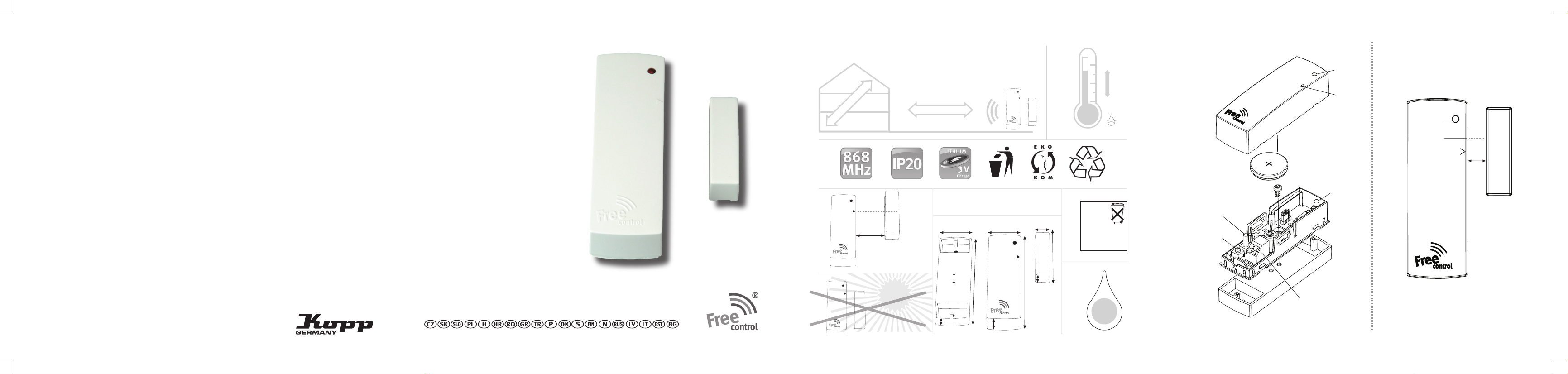
Statusmeldung
Statusmeldung wird ca. alle 4 Stunden gesendet.
Überwacht wird:
• Batteriekapazität • Magnetkontakt intern
• Sabotagekontakt • externer Kontakt
Hinweise
Mit Free-control schalten Sie einfach, komfortabel
und bequem Ihre Elektrogeräte. Ein funktionsfähiges
Funksystem besteht in der Minimalausführung immer
aus einem Funk-Sender und einem Funk-Empfänger. Bei
Free-control (mit Logo: ) können alle Sender mit allen
Empfängern verknüpft werden, Ausnahme für Geräte mit
folgenden Artikelnummern xxxx.xxx1.x (mit Logo: ).
Haftungen oder weitergehende andere Ansprüche,
insbesondere solche auf Ersatz außerhalb des
Gerätes entstehender Personen- oder Sachschäden,
durch keine oder fehlerhafte Funktionen sind ausge-
schlossen.
Alle Sendecodes sind werkseitig eingestellt und
können nicht verändert werden.
Die Funkübertragung erfolgt auf einem nicht exklusiv
verfügbaren Frequenzkanal mit 868 MHz. Störungen
sind daher nicht auszuschließen.
Die Funkreichweite ist abhängig von Sendeleistung,
Störeinflüssen und baulichen Gegebenheiten.
Die Empfangssicherheit nimmt mit zunehmenden
Abstand zwischen Sendern und Empfängern ab. In
Gebäuden ist die Reichweite abhängig von den dort
eingesetzten Baumaterialien.
Material Typische Reichweite
Mauerwerk 20m - max. durch 3 Wände
Stahlbeton 10m - max. durch 1 Wand/Decke
Gipskarton/Holz 30m - max. durch 5 Wände
Free-control Funktechnik ist nicht geeignet für Si-
cherheitsanwendungen, z.B. NOT-AUS, NOT-RUF.
Beachten Sie die Regeln der Elektrotechnik und die
technischen Daten!
Führen Sie keine Änderungen an den Geräten durch.
Änderungen aufgrund technischen Fortschritts, Nor-
menänderungen, veränderter Fertigungsverfahren
oder Konstruktionsänderungen bleiben ausdrücklich
vorbehalten.
Für den Betrieb in EU, EFTA-Mitgliedsstaaten zugelassen.
Weitere Informationen, Anwendungsbeispiele,
Sortimentsübersicht, Bedienungsanleitungen in je-
weiliger Landessprache unter www.free-control.com

5
Please read the operating instructions carefully!
Dependable early warning and protection against
burglary is only ensured if this radio magnetic
sensor is used in accordance with the following
instructions.
Application
Monitoring of doors and windows. Detects the ope-
ning or closing of doors and windows.
Monitoring of objects to prevent unauthorized
removal.
Mounting
Select a suitable mounting location. Drilling guide
exists. Plastic base for height adjustment .
Before final mounting, please check to ensure that
the intended receiver reliably receives the radio sig-
nal of the magnetic contact. If necessary, change the
position of the receiver or the magnetic sensor.
The center of the magnet must match the arrow posi-
tion on the housing of the radio magnetic sensor .
Note: Do not mount on or near metal surfaces (e.g.
hinges, fittings, frames).
Power supply
3 V lithium battery CR 2450.
Battery life up to 2.5 years.
LED blinks 1x when the battery is inserted .
Ensure correct battery polarity.
Battery capacity is monitored.
Recommendation: Replace battery every 2 years
Sabotage contact
For proper operation, install the housing lid correctly
= sabotage contact closed. A sabotage message is
transmitted in case of attempted sabotage.
External contact
A second monitoring loop in the form of an additi-
onal contact can be connected . This can be
an additional magnetic contact, reed contact or
other contact. Electronics automatically detect the
additional contact after this has been closed. Radio
magnetic sensor and external contact work synchro-
nously/parallel.
Without external contact:
Terminals can remain open.
Wire jumper not necessary .
Status display
LED blinks 1x when the battery is inserted and
then goes out:
• Battery full
• Device ready for operation
LED flashes 1x per minute:
• Battery weak
• Alarm recognition still possible
• Signal broadcast still possible
LED blinks quickly:
• Battery almost empty
• Alarm recognition no longer possible
• Signal broadcast no longer possible

6
Function setting
Radio magnetic sensor is only a transmitter.
Any number of receivers in the transmitting range
can be programmed to the switching command.
Combination with other free-control devices
Plug the plug-in jumper into position for the
following applications:
• Signal evaluation by means of the radio alarm
station
• Switching of radio receivers
- Flush-mounted receiver 1-channel 3-wire
- Flush-mounted receiver 1-channel 2-wire
- Flush-mounted receiver 2-channel or blinds
- Flush-mounted receiver buttons or time function
- Flush-mounted receiver dimmer function for
electronic transformers (switch on/off function)
- Flush-mounted receiver dimmer function for
conventional transformers (switch on/off function)
- Lamp socket
- Adapter switch function
- Adapter dimmer function (switch on/off function)
- Grounding-type multiple socket outlet
Sabotage contact is not active here.
Plug the plug-in jumper into position for the
following applications:
• Signal evaluation by the radio burglary alarm
center
• Signal evaluation by the PC-software for burglary
alarm center
Sabotage contact and magnetic sensor are constantly
monitored here.
Programming to radio receiver and/or radio alarm station
Set plug-in jumper .
Activate the programming mode of the receiver (see
separate operating instructions).
Select the switching behavior of the magnetic sen-
sor for the operating scenario. To do this, press the
PROG button for different lengths of time.
Operating scenario 1:
Transmit the signal „switch ON command“ if a door
or window is closed.
Transmit the signal „switch OFF command“ if a door
or window is opened.
Set operating scenario 1:
Press PROG button < 1 second.
LED illuminates for 3 seconds.
Magnetic sensor transmits two signals
First ON then OFF signal within 2 seconds
Receiver LED must blink 2x.
Programming process is terminated automatically.
Operating scenario 2:
Transmit the signal „switch ON command“ if a door
or window is opened.
Transmit the signal „switch OFF command“ if a door
or window is closed.
Set operating scenario 2:
Press PROG button > 2 seconds.
LED blinks briefly
Magnetic sensor transmits two signals:
First OFF then ON signal within 2 seconds
Receiver LED must blink 2x.
Programming process is terminated automatically.

7
Programming to radio burglary alarm center and/or
PC-software for burglary alarm center
Set plug-in jumper .
Activate the programming mode of the radio bur-
glary alarm center, PC-software for burglary alarm
center (see separate operating instructions).
Press PROG button .
LED illuminates approximately 3 seconds.
Programming process is terminated automatically.
Caution:
The magnetic contact must have been closed for at
least 2 minutes between two signal broadcasts.
A radio signal is sent after each opening of the
magnetic contact .
Then, detection is blocked for approx. 2 minutes.
The magnetic contact must be closed again for ap-
prox. 2 minutes for the next signal transmission.
If the opening of the contact is once again detected
within this blocking period of approx. 2 minutes, no
radio signal is sent.
The blocking period of approx. 2 minutes begins
once again, however.
If programming was not successful:
Note instructions in the troubleshooting section
(FAQ) at www.free-control.com.
Status notification
Status notification is transmitted approximately
every 4 hours.
The following is monitored:
• Battery capacity
• Internal magnetic contact
• Sabotage contact
• External contact
Notes
With Free-control, you can easily, comfortably,
and conveniently switch your electrical devices. A
minimum functional radio system always consists
of a radio-transmitter and a radio-receiver. With
Free-control (with logo: ), all transmitters can be
linked with all receivers, except for devices with the
following article numbers xxxx.xxx1.x (with logo: ).
Liability or any other claims, especially for the reim-
bursement of personal or property damages outside
of the device caused by lack of function or malfunc-
tion are excluded.
All transmitting codes are set at the factory and
cannot be changed.
The radio transmission takes place over a non-ex-
clusive frequency channel of 868 MHz. Malfunctions
are therefore not impossible.
The radio range depends upon transmitting power,
disruptions, and structural conditions.
The reliability of reception decreases with increa-
sing distance between transmitters and receivers.
In buildings, the range depends upon the building
materials used.

Typical range based on material
Masonry 20m - through a maximum of 3 walls
Reinforced concrete 10m - through a maximum of 1 wall/floor
Plasterboard/wood 30m - through a maximum of 5 walls
Free-control radio technology is not suitable for
safety applications, such as EMERGENCY STOP,
EMERGENCY CALL.
Follow the rules of electrical engineering and the
technical data!
Do not make any changes to the devices.
We expressly reserve the right to make changes
due to technical progress, changes in standards,
changes to production procedures, or construction
changes.
Certified for operation in EU, EFTA-member states.
For additional information, application examples,
assortment overview, and operating instructions in
the respective language of a country, see
www.free-control.com
The declaration of conformity can be found under
the following address:
Heinrich Kopp GmbH • Alzenauer Straße 68 • 63796
Kahl am Main oder www.free-control.com
8

De bedieningshandleiding aandachtig lezen!
Een betrouwbare vroegtijdige waarschuwing en be-
scherming tegen inbraak is enkel mogelijk wanneer
deze radio-magneetsensor in overeenstemming met
de volgende aanwijzingen gebruikt wordt.
Gebruik
Controle van deuren en vensters. Herkent het ope-
nen of sluiten van deuren en vensters. Controle van
voorwerpen tegen onbevoegd verwijderen.
Montage
Een passende montageplaats kiezen. Kunststof
onderdeel voor hoogtecompensatie .
Voor de definitieve montage controleren of de voor-
ziene ontvanger het radiosignaal van het magneet-
contact goed ontvangt. Eventueel de positie van de
ontvanger of de magneetsensor veranderen.
Het midden van de magneet moet met de pijlposi-
tie op de behuizing van de radio-magneetsensor
overeenstemmen .
Opmerking: Niet op of in de buurt van metalen
oppervlakken (bijvoorbeeld scharnieren, kaders)
monteren.
Spanningsverzorging
3 V lithiumbatterij CR 2450.
Levensduur van de batterij max. 2,5 jaar.
De LED knippert 1 x wanneer de batterij inge-
legd wordt.
Op de juiste polen van de batterij letten.
De capaciteit van de batterij wordt gecontroleerd.
Aanbeveling: de batterij om de 2 jaren vervangen.
Sabotagecontact
Voor een perfect bedrijf, het behuizingsdeksel cor-
rect aanbrengen = sabotagecontact gesloten.
Bij een poging tot sabotage wordt een sabotagemel-
ding verzonden.
Extern contact
Een tweede controlelus in de vorm van een bijko-
mend contact kan aangesloten worden .
Dit kan een bijkomend potentiaalvrij magneetcon-
tact, Reedcontact of een ander contact zijn.
De elektronica herkent een bijkomend contact auto-
matisch nadat dit een keer gesloten werd.
De radio-magneetsensor en het externe contact
werken gelijkwaardig / parallel.
Zonder extern contact:
De aansluitingsklemmen kunnen open blijven.
Draadbrug niet noodzakelijk .
Bedrijfsindicatie
De LED knippert 1x wanneer de batterij 5 inge-
legd wordt en gaat dan uit:
• Batterij vol
• Toestel bedrijfsklaar
De LED knippert 1x per minuut:
• Zwakke batterij
• Alarmherkenning nog mogelijk
• Signaalverzending nog mogelijk
9

10
De LED knippert snel:
• Batterij bijna leeg
• Alarmherkenning niet meer mogelijk
• Signaalverzending niet meer mogelijk
Functie-instelling
De radio-magneetsensor is uitsluitend zender.
Er kunnen willekeurig veel ontvangers in het zendbe-
reik op het schakelbevel ingesteld worden.
Combinatie met andere Free-control toestellen
De steekbrug voor de volgende toepassingen in
positie s teken:
• Signaalevaluatie door het radio-alarmstation
• Schakelen van radio-ontvangers
- UP ontvanger 1kanaal 3draad
- UP ontvanger 1kanaal 2draad
- UP ontvanger 2kanaal of rolluik
- UP ontvanger toets of tijdfunctie
- UP ontvanger dimfunctie voor elektronische
transformators (in-/uitschakelfunctie)
- UP ontvanger dimfunctie voor traditionele
transformators (in-/uitschakelfunctie)
- Lampenhouder
- Adapter schakelfunctie
- Adapter dimfunctie (in-/uitschakelfunctie)
- Veiligheidscontact-contactdooslijst
Het sabotagecontact is hierbij niet actief.
De steekbrug voor de volgende toepassing in positie
steken:
• Signaalevaluatie door de radio-inbraakalarmcentrale
• Signaalevaluatie door de PC-software voor inbraa
kalarmcentrale
Het sabotagecontact en de magneetsensor worden
hierbij permanent gecontroleerd.
Instellen op de radio-ontvanger en/of het radio-alarmstation
De steekbrug instellen . De leermodus van de
ontvanger activeren (zie de separate bedienings-
handleiding).
Het schakelgedrag van de magneetsensor voor het
bedrijfsgeval selecteren. Daarvoor de PROG toets
verschillend lang indrukken.
Bedrijfsgeval 1:
Het signaal „IN-schakelbevel“ bij het sluiten van een
deur of een venster verzenden.
Het signaal „UIT-schakelbevel“ bij het openen van
een deur of een venster verzenden.
Bedrijfsgeval 1 instellen:
De PROG toets < 1 seconden indrukken.
De LED licht 3 seconden op.
De magneetsensor verstuurt twee signalen.
Eerst IN dan UIT signaal binnen 2 seconden.
De ontvanger LED moet 2x knipperen.
De leerprocedure wordt automatisch beëindigd.
Bedrijfsgeval 2:
Het signaal „IN-schakelbevel“ bij het sluiten van een
deur of een venster verzenden.
Het signaal „UIT-schakelbevel“ bij het openen van
een deur of een venster verzenden.
Bedrijfsgeval 2 instellen:
De PROG toets > 2 seconden indrukken
De LED knippert kort
De magneetsensor verstuurt twee signalen:
Eerst IN dan UIT signaal binnen 2 seconden
De ontvanger LED moet 2x knipperen.
De leerprocedure wordt automatisch beëindigd.

11
Instellen op de radio-inbraakalarmcentrale en/of PC-
software voor inbraakalarmcentrale
De steekbrug instellen .
De instellingsmodus van de radio-inbraakalarmcen-
trale, PC-software voor inbraakalarmcentrale active-
ren (zie de separate bedieningshandleiding).
De PROG toets indrukken.
De LED licht ca. 3 seconden op.
De instellingsprocedure wordt automatisch beëindigd.
Let op:
Tussen twee signaaluitzendingen moet het magneet-
contact minstens 2 minuten gesloten geweest zijn.
Telkens wanneer het magneetcontact geopend wordt,
wordt een radiosignaal gezonden.
Daarna wordt de herkenning ca. 2 minuten geblok-
keerd.
Het magneetcontact moet voor de volgende signaalu-
itzending opnieuw ca. 2 minuten gesloten zijn.
Wordt binnen deze blokkeertijd van ca. 2 minuten
herkend dat het contact geopend is, wordt geen
radiosignaal gezonden.
De blokkeertijd van ca. 2 minuten begint echter
opnieuw.
Is de programmering mislukt:
De aanwijzingen in de rubriek Troubleshooting (FAQ)
op www.free-control.com in acht nemen.
Statusmelding
De statusmelding wordt ca. om de 4 uur verzonden.
Gecontroleerd wordt:
• Batterijcapaciteit
• Magneetcontact intern
• Sabotagecontact
• extern contact
Aanwijzingen
Met Free-control schakelt u uw elektrische toestellen
eenvoudig, comfortabel en eenvoudig. Een goed
werkend systeem bestaat in de minimale uitvoering
uit een radiozender en een radio-ontvanger. Bij Free-
control (met logo: ) kunnen alle zenders met alle
ontvangers verbonden worden, uitzondering gemaakt
voor toestellen met de volgende artikelnummers xxxx.
xxx1.x (met logo: ).
Aansprakelijkheidsclaims of andere claims, vooral
met betrekking tot vergoeding van persoonlijke of
materiële schade die buiten het toestel ontstaat door
geen of gebrekkige functies zijn uitgesloten.
Alle zendcodes zijn in de fabriek ingesteld en kunnen
niet veranderd worden.
De radiotransmissie gebeurt op een niet exclusief be-
schikbaar frequentiekanaal met 868 MHz. Storingen
zijn daarom niet uit te sluiten.
De radioreikwijdte is afhankelijk van het zendvermo-
gen, storingen en constructieve eigenschappen.
De ontvangstzekerheid neemt met toenemende af-
stand tussen zenders en ontvangers af. In gebouwen
is de reikwijdte afhankelijk van de daar gebruikte
bouwmaterialen.

12
Materiaal - Typische reikwijdte
Metselwerk 20m - max. door 3 wanden
Staalbeton 10m - max. door 1 wand/plafond
Gipskarton/hout 30m - max. door 5 wanden
De Free-control radiotechniek is niet geschikt voor
veiligheidstoepassingen, zoals NOODSTOP, NOODO-
PROEP.
De regels van de elektrotechniek en de technische
gegevens naleven!
Geen veranderingen aan de toestellen uitvoeren.
Veranderingen wegens de technische vooruitgang,
veranderde normen, veranderde productiemetho-
den of constructiewijzigingen blijven uitdrukkelijk
voorbehouden.
Voor het bedrijf in EU-, EFTA-lidstaten toegelaten.
Voor meer informatie, toepassingsvoorbeelden,
assortimentoverzicht, bedieningshandleidingen in
uw taal, ga naar www.free-control.com
De conformiteitverklaring kan onder het volgende
adres gevonden worden:
Heinrich Kopp GmbH • Alzenauer Straße 68 • 63796
Kahl am Main oder www.free-control.com

13
Prière de lire soigneusement le mode d’emploi !
Une alerte anticipée fiable et la protection contre
les effractions ne sont possibles que si ce capteur
magnétique radio est utilisé conformément aux
instructions suivantes.
Utilisation
Surveillance de portes et de fenêtres. Enregistre
l’ouverture ou la fermeture de portes et de fenêtres.
Surveillance d‘objets ne devant pas être enlevés
sans autorisation.
Montage
Choisir un emplacement adéquat. Socle plastique
pour compensation de la hauteur .
Avant le montage définitif, vérifier SVP que le récep-
teur prévu reçoit parfaitement le signal radio émis
par le contact magnétique. Modifier, le cas échéant,
la position du récepteur ou du contact magnétique.
Le centre de l’aimant doit concorder avec la position de
la flèche sur le boîtier du capteur magnétique radio .
Remarque : ne pas installer l’appareil à proximité
de surfaces métalliques ou sur ces surfaces (par ex.
charnières, ferrures, encadrements).
Alimentation électrique
Pile lithium 3 V CR 2450.
Durée de vie de la pile jusqu’à 2,5 ans.
La DEL clignote 1 fois quand la pile est insérée .
Respecter la polarité de la pile.
Surveillance de la capacité de la pile.
Conseil : remplacer la pile tous les 2 ans.
Contact anti-sabotage
Placer correctement le couvercle du boîtier pour
garantir un fonctionnement parfait = contact anti-
sabotage fermé.
Toute tentative de sabotage déclenche l‘envoi d‘un
message.
Contact externe
Il est possible de connecter une seconde boucle
de contrôle représentée par un contact supplémen-
taire . Cela peut être un autre contact magnétique
hors potentiel, un contact Reed ou tout autre type
de contact.
Le système électronique identifie automatique
le contact supplémentaire dès que celui-ci a été
connecté.
Le capteur magnétique radio et le contact externe
travaillent en équivalence / en parallèle.
Sans contact externe :
les bornes de raccordement peuvent rester ouver-
tes. Un pontage n’est pas nécessaire .
Témoin de fonctionnement
La DEL clignote 1 fois quand la pile est insérée
et s‘éteint ensuite :
• pile pleine
• appareil prêt à fonctionner
La DEL s’allume rapidement 1 fois par minute :
• pile faible
• identification de l’alarme encore possible
• émission d’un signal encore possible

14
La DEL clignote rapidement :
• pile presque vide
• identification de l’alarme n’est plus possible
• émission d‘un signal n’est plus possible
Réglage des fonctions
Le capteur magnétique radio est uniquement
émetteur. Dans la zone d’émission, le processus
d’apprentissage de l’instruction de commutation peut
être appliqué à autant de récepteurs que l’on veut.
Combinaison avec d’autres appareils Free-control
Placer le cavalier enfichable en position pour les
applications suivantes :
• analyse du signal par la station d’alarme radio
• commutation de récepteurs radio
- Récepteur encastré 1 canal 3 fils
- Récepteur encastré 1 canal 2 fils
- Récepteur encastré 2 canaux ou volet roulant
- Récepteur encastré palpeur ou fonction de temps
- Récepteur encastré fonction de variateur pour
transformateurs électroniques (fonction marche/arrêt)
- Récepteur encastré fonction de variateur pour
transformateurs conventionnels (fonction
marche/arrêt)
- Culot de lampe
- Adaptateur fonction de commutation
- Adaptateur fonction de variateur (fonction
marche/arrêt)
- Multiprise de sécurité
Le contact anti-sabotage n’est alors pas actif.
Placer le cavalier enfichable en position pour les
applications suivantes :
• analyse du signal par la centrale d’alarme effrac-
tions radio
• analyse du signal par le logiciel PC pour centrale
d’alarme effractions
Le contact anti-sabotage et le capteur magnétique
sont alors surveillés en permanence.
Apprentissage récepteur radio et / ou station
d’alarme radio
Régler le cavalier enfichable . Activer le mode
d’apprentissage du récepteur (lire le mode d’emploi séparé).
Sélectionner le comportement de commutation du
capteur magnétique pour le cas de fonctionnement.
Pour cela, appuyer pendant plus ou moins longt-
emps sur la touche PROG .
Cas de fonctionnement 1 :
Émission du signal « Instruction de commutation
ACTIVATION » lors de la fermeture d’une porte ou
d’une fenêtre.
Émission du signal « Instruction de commutation
DÉSACTIVATION » lors de l’ouverture d’une porte ou
d’une fenêtre.
Réglage du cas de fonctionnement 1 :
appuyer < 1 seconde sur la touche PROG
La DEL clignote pendant 3 secondes.
Le capteur magnétique émet deux signaux :
signal ACTIVATION puis signal DÉSACTIVATION dans
un délai de 2 secondes
Le récepteur DEL doit clignoter 2 fois.
Le processus d’apprentissage se termine automatiquement.

15
Cas de fonctionnement 2 :
émission du signal « Instruction de commutation
ACTIVATION » lors de l’ouverture d’une porte ou
d’une fenêtre.
Émission du signal « Instruction de commutation
DÉSACTIVATION » lors de la fermeture d’une porte ou
d’une fenêtre.
Réglage du cas de fonctionnement 2 :
appuyer > 2 secondes sur la touche PROG
La DEL clignote rapidement
Le capteur magnétique émet deux signaux :
d‘abor le signal DÉSACTIVATION puis le signal ACTI-
VATION dans un délai de 2 secondes
Le récepteur DEL doit clignoter 2 fois.
Le processus d’apprentissage se termine automati-
quement.
Apprentissage centrale d’alarme effractions radio et
/ ou logiciel PC pour centrale d’alarme effractions
Régler le cavalier enfichable .
Activer mode d’apprentissage de la centrale
d’alarme effractions radio, logiciel PC pour centrale
d’alarme effraction (lire le mode d’emploi séparé).
Appuyer sur la touche « PROG » .
La DEL clignote pendant 3 secondes environ.
Le processus d’apprentissage se termine automati-
quement.
Attention :
entre deux émissions de signaux, le contact mag-
nétique doit avoir été fermé pendant au moins 2
minutes.
Un signal radio est émis après chaque ouverture du
contact magnétique.
Ensuite, la détection est inactive pendant 2 minutes
environ.
Pour l’émission de signal suivante, le contact mag-
nétique doit être refermé pour 2 minutes env.
Si une nouvelle ouverture du contact est détectée
pendant cet intervalle inactif de 2 minutes env.,
aucun signal radio n’est émis.
Toutefois, l’intervalle inactif de 2 minutes env. repart
de zéro.
Si la programmation a échoué :
consulter les informations à la rubrique Recherche
de pannes (FAQ) sur www.free-control.com.
Information du statut
L’information du statut est envoyée toutes les 4
heures environ.
Le contrôle concerne :
• la capacité de la pile
• le contact magnétique interne
• le contact anti-sabotage
• le contact externe
Remarques
Free-control vous permet de commuter facilement
et en toute convivialité vos appareils électriques.
Un système radio comprend au moins toujours un
émetteur radio et un récepteur radio pour pouvoir être
opérationnel. Chez Free-control (avec logo : ), tous
les émetteurs peuvent être connectés avec tous les
récepteurs, exception faite des appareils ayant les nu-
méros d’article suivants xxxx.xxx1.x (avec logo : ).

16
Toute responsabilité ou autre revendication, no-
tamment en raison du remplacement de dommages
personnels ou matériels survenus en dehors de
l‘appareil par une absence de fonction ou une fonc-
tion défaillante sont exclues.
Tous les codes d’émission sont paramétrés en usine
et ne peuvent pas être modifiés.
La transmission radio se fait sur un canal de
fréquence (868 MHz) dont la disponibilité n’est pas
exclusive. Des perturbations ne peuvent donc pas
être exclues.
La portée radio dépend de la puissance d’émission,
de l’influence de perturbations et du type de
construction.
Plus l‘écart entre émetteurs et récepteurs augmen-
te, plus la sécurité de réception diminue. Dans
les bâtiments, la portée dépend des matériaux de
construction employés.
Portée selon le matériel
Maçonnerie 20 m - au max. à travers 3 murs
Béton armé 10 m - au max. à travers 1 mur / plafond
Placoplâtre/bois 30 m - au max. à travers 5 murs
La technique radio de Free-control ne convient pas
pour les applications de sécurité telles que ARRÊT
D‘URGENCE ou APPEL D‘URGENCE.
Respectez les directives en vigueur dans le domaine
électrotechnique et les données techniques !
Ne modifiez pas les appareils.
Sous réserve expresse de modifications pour pro-
grès techniques, actualisation de normes, modifica-
tions du processus de fabrication ou changements
de conception.
Homologué pour l‘utilisation dans l‘UE et les pays
membres de l’AELE.
Vous trouverez sur www.free-control.com des
informations supplémentaires, des exemples
d’utilisation, une présentation de la gamme et des
modes d’emploi dans plusieurs langues.
La déclaration de conformité est disponible à
l’adresse suivante :
Heinrich Kopp GmbH • Alzenauer Straße 68 • 63796
Kahl am Main oder www.free-control.com

17
Leggere attentamente le istruzioni per l‘uso!
Solo l‘utilizzo di questo radiosensore magnetico
nel rispetto delle seguenti istruzioni garantisce la
segnalazione tempestiva e affidabile di un tentativo
di effrazione.
Applicazione
Monitoraggio di porte e finestre. Rileva l‘apertura o
chiusura di porte e finestre.
Monitora la rimozione non autorizzata di oggetti.
Montaggio
Scegliere un luogo di montaggio idoneo. Base in
plastica per il livellamento in altezza .
Prima del montaggio definitivo verificare che il rice-
vitore previsto riceva correttamente il segnale radio
del contatto magnetico. Modificare eventualmente la
posizione del ricevitore o del sensore magnetico.
Il centro del magnete deve coincidere con la posizio-
ne della freccia sull‘involucro del radio sensore .
Nota: non montare su o in prossimità di superfici
metalliche (per es. cerniere, rivestimenti, telai).
Alimentazione di tensione
Batteria al litio 3 V CR 2450
Durata della batteria fino a 2,5 anni.
Il LED lampeggia all‘inserimento della batteria .
Fare attenzione alla corretta polarità della batteria.
La capacità della batteria è monitorata.
Raccomandazione: sostituire la batteria ogni 2 anni
Contatto antisabotaggio
Per un funzionamento perfetto, posizionare corret-
tamente il coperchio dello scomparto = contatto
antisabotaggio chiuso.
In caso di tentativo di sabotaggio, verrà inviato un
messaggio.
Contatto esterno
È possibile collegare un secondo circuito di monito-
raggio sotto forma di contatto supplementare .
Può essere un contatto magnetico privo di potenziale,
un contatto reed o di altro tipo. L‘elettronica rileva auto-
maticamente il contatto supplementare dopo che è stato
chiuso uno volta. Il radiosensore magnetico e il contatto
esterno funzionano simultaneamente/in parallelo.
Senza contatto esterno:
I morsetti di collegamento possono restare aper-
ti. Ponte a filo superfluo .
Indicatore di funzionamento
Il LED lampeggia 1 volta all‘inserimento della
batteria e poi smette:
• Batteria carica
• Apparecchio pronto per l‘uso
Il LED lampeggia 1 volta al minuto:
• Batteria debole
• Possibile rilevare ancora l‘allarme
• Possibile emettere ancora il segnale
Il LED lampeggia rapidamente:
• Batteria quasi scarica
• Non è più possibile rilevare l‘allarme
• Non è più possibile emettere il segnale

18
Impostazione delle funzioni
Il radiosensore magnetico è esclusivamente
trasmettitore. Si possono inizializzare al comando
di commutazione tutti i ricevitori desiderati nella
gamma di trasmissione.
Combinazione con altri apparecchi Free-control
Portare in posizione il ponte a innesto per le
seguenti applicazioni:
• Interpretazione di segnale tramite radiostazione
di allarme
• Commutazione di radioricevitori
- Ricevitore sottointonaco monocanale 3 fili
- Ricevitore sottointonaco monocanale 2 fili
- Ricevitore sottointonaco bicanale o avvolgibili
- Tasto ricevitore sottointonaco o funzione temporale
- Funzione crepuscolare ricevitore sottointonaco
per trasformatori elettronici (funzione ON/OFF)
- Funzione crepuscolare ricevitore sottointonaco
per trasformatori tradizionali (funzione ON/OFF)
- Portalampada
- Funzione di commutazione adattatore
- Funzione crepuscolare adattatore (funzione ON/OFF)
- Ciabatta multipresa con contatto di protezione
Il contatto antisabotaggio in questo caso non è
attivo.
Portare in posizione il ponte a innesto per le
seguenti applicazioni:
• Interpretazione di segnale tramite radiocentralina
di allarme antieffrazione
• Interpretazione di segnale tramite software PC
per centralina di allarme antieffrazione
Contatto antisabotaggio e sensore magnetico in
questo caso sono monitorati costantemente.
Inizializzazione per radioricevitore e/o radiostazio-
ne di allarme
Regolare il ponte a innesto . Attivare la modalità
di inizializzazione del ricevitore (leggere le istruzioni
per l‘uso separate).
Selezionare la modalità di commutazione del senso-
re magnetico per il tipo di funzionamento, premendo
per un tempo di durata differente il tasto PROG .
Tipo di funzionamento 1:
Invio del segnale „Comando di commutazione ON“
alla chiusura di una porta o finestra.
Invio del segnale „Comando di commutazione OFF“
all‘apertura di una porta o finestra.
Impostare il tipo di funzionamento 1:
Premere il tasto PROG < 1 secondo.
Il LED si accende per 3 secondi.
Il sensore magnetico invia due segnali.
Prima segnale ON poi OFF entro 2 secondi.
Il LED del ricevitore deve lampeggiare 2 volte.
La fase di inizializzazione si conclude in automatico.
Tipo di funzionamento 2:
Invio del segnale „Comando di commutazione ON“
all‘apertura di una porta o finestra.
Invio del segnale „Comando di commutazione OFF“
alla chiusura di una porta o finestra.
Impostare il tipo di funzionamento 2:
Premere il tasto PROG > 2 secondi.
Il LED lampeggia brevemente.

19
Il sensore magnetico invia due segnali.
Prima segnale OFF poi ON entro 2 secondi.
Il LED del ricevitore deve lampeggiare 2 volte.
La fase di inizializzazione si conclude in automatico.
Inizializzazione per radiocentralina di allarme antieffrazione
e/o software PC per centralina di allarme antieffrazione.
Regolare il ponte a innesto .
Attivare la modalità di inizializzazione di radiocen-
tralina di allarme antieffrazione, software PC per
centralina di allarme antieffrazione (leggere le istru-
zioni per l‘uso separate). Premere il tasto PROG .
Il LED lampeggia per ca. 3 secondi.
La fase di inizializzazione si conclude in automatico.
Attenzione:
tra due emissioni di segnale il contatto magnetico
deve essere stato chiuso per almeno 2 minuti.
A ogni apertura del contatto magnetico viene emes-
so un segnale radio.
Successivamente il rilevamento resta bloccato per
ca. 2 minuti.
Il contatto magnetico deve essere nuovamente
chiuso per ca. 2 minuti per la successiva emissione
di segnale.
Se entro il tempo di interdizione di ca. 2 minuti
viene nuovamente rilevata l‘apertura del contatto,
non vengono emessi segnali radio.
Il tempo di interdizione di ca. 2 minuti però riprende.
Se la programmazione non ha avuto successo:
Leggere le istruzioni nella rubrica Ricerca errori
(FAQ) all‘indirizzo www.free-control.com.
Messaggio di stato
Il messaggio di stato viene inviato ogni 4 secondi.
Sono monitorati:
• capacità della batteria
• contatto magnetico interno
• contatto antisabotaggio
• contatto esterno
Istruzioni
Grazie a Free-control si possono attivare gli elettro-
domestici in modo pratico, semplice e in tutta como-
dità. La versione base di un radiosistema funzionan-
te consiste sempre in un radiotrasmettitore ed un
radioricevitore. In Free-control (con logo: ) tutti
i radiotrasmettitori sono combinabili con qualsiasi
radioricevitore, fanno eccezione gli apparecchi con i
codici articolo seguenti xxxx.xxx1.x (con logo: ).
Si escludono responsabilità o ulteriori diritti, in
particolare di risarcimento dei danni occorsi a cose
o persone al di fuori dell‘apparecchio e dovuti a
funzionamento mancato o difettoso.
Tutti i codici di trasmissione sono impostati di
fabbrica e non possono essere modificati.
La trasmissione radio avviene su un canale di
frequenza non esclusivo a 868 MHz. Non si possono
perciò escludere disturbi.
La portata radio dipende dalla potenza di trasmissi-
one, da fattori di disturbo ed elementi architettonici.
La sicurezza di ricezione diminuisce con il crescere
della distanza tra trasmettitori e ricevitori. La portata
negli edifici dipende dai materiali da costruzione
impiegati in loco.

20
Materiale - Portata tipica
Muratura 20 m - max attraverso 3 pareti
Cemento armato 10 m - max attraverso 1 parete/soffitto
Cartongesso/Legno 30 m - max attraverso 5 pareti
La radiotecnologia di Free-control non è indicata per
applicazioni di sicurezza, come per es. ARRESTO DI
EMERGENZA, CHIAMATA DI EMERGENZA.
Osservare le regole dell‘elettrotecnica e i dati tecnici!
Non apportare modifiche agli apparecchi.
Con riserva espressa di modifiche dovute a progres-
so tecnologico, variazioni di norme, modifiche nella
procedura di fabbricazione o modifiche strutturali.
Omologato per il funzionamento nella UE e negli
stati membri dell‘EFTA
Per ulteriori informazioni, esempi di applicazione,
una panoramica della gamma, istruzioni per l‘uso
nella lingua del proprio paese visitare il sito
www.free-control.com.
La dichiarazione di conformità è reperibile
all‘indirizzo seguente:
Heinrich Kopp GmbH • Alzenauer Straße 68 • 63796
Kahl am Main oder www.free-control.com
Table of contents
Languages:
Other Kopp Accessories manuals
Popular Accessories manuals by other brands

delight smart solutions
delight smart solutions 55376 User manual and installation guide

PCB Piezotronics
PCB Piezotronics ICP 208A24 Installation and operating manual

BAC
BAC TrilliumSeries TRF-1010N-C80GX17E Rigging & Assembly Instructions

clare
clare CLR-C1-ODDG Installation sheet

WeighTech
WeighTech WT3000-P manual

TP-Link
TP-Link PB50 user guide

Beninca
Beninca SC.P30QIS quick start guide

Tejovat Smart Home Products
Tejovat Smart Home Products TJ-SH-DP1500 user manual

Emerson
Emerson Micro Motion F Series installation manual

Leviton
Leviton T6525-I quick start guide

Rice Lake
Rice Lake Revolution 680 Synergy Plus Technical manual

MEL Systems
MEL Systems Tele4 brochure