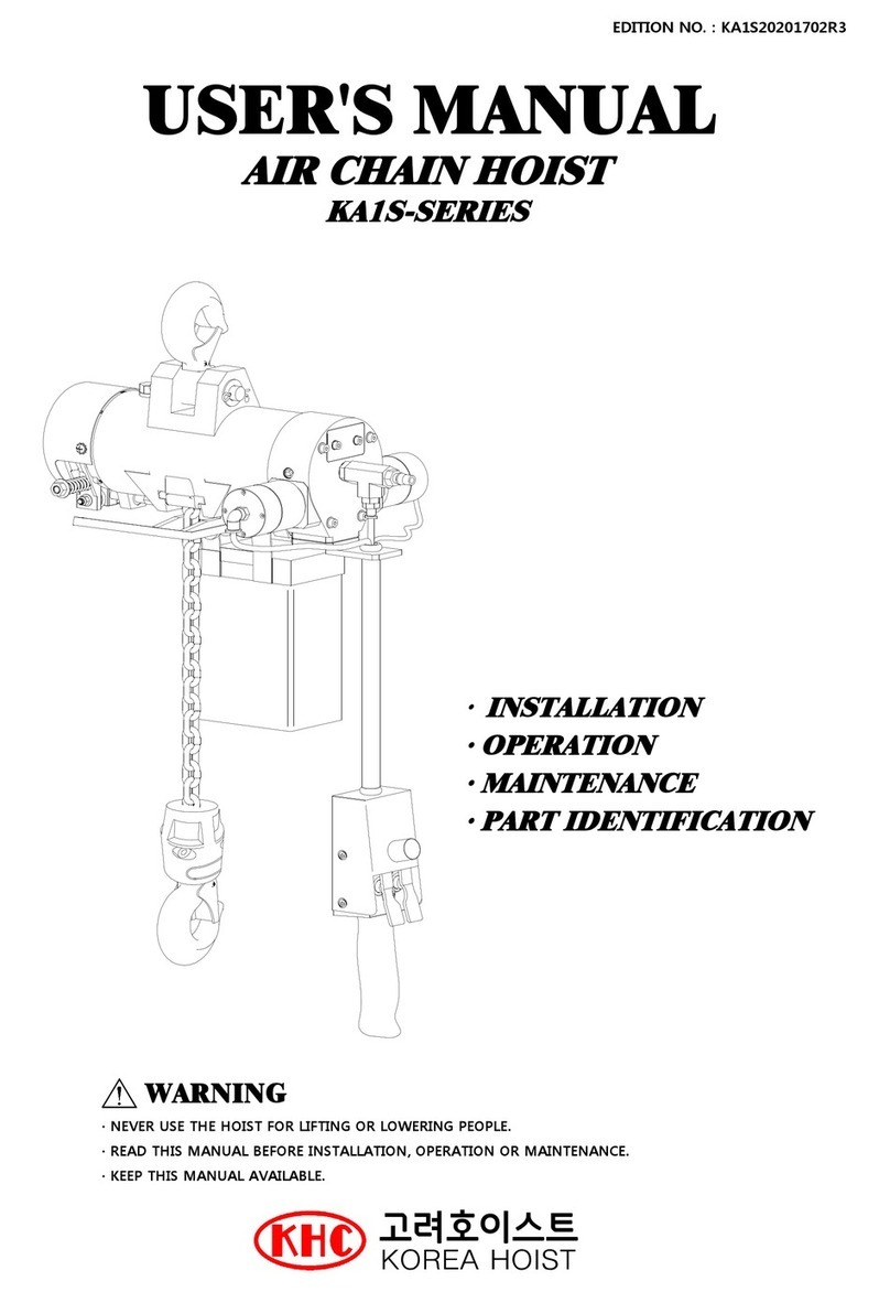
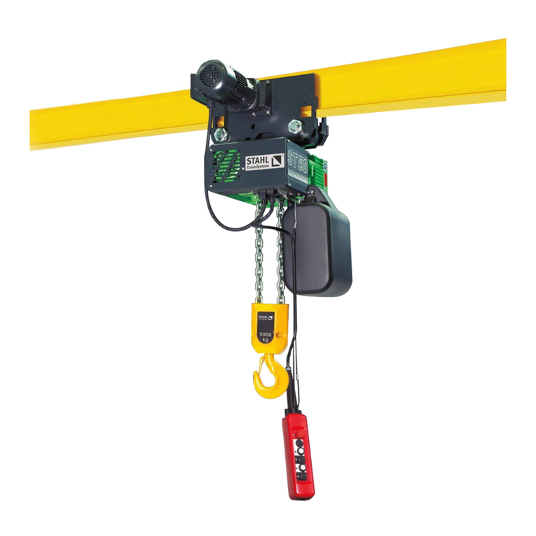
Korea Hoist KA2M Series User manual

1
AIR CHAIN HOIST
KA2M-SERIES
USER'S MANUAL
EDITION NO. : KA2M20207102R2
WARNING
NEVER USE THE HOIST FOR LIFTING OR LOWERING PEOPLE.
READ THIS MANUAL BEFORE INSTALLATION, OPERATION OR MAINTENANCE.
KEEP THIS MANUAL AVAILABLE.

CONTENTS
1. Safety instructions before completing installation ------------------ 2
1.1 General safety information ------------------ 2
1.2 Air supply and lubrication ------------------ 2
1.3 Safety instructions for operators ------------------ 2
2. Specificationtion ------------------ 2
3. Inspection regulations before completion installation ------------------ 3
4. Installation ------------------ 3
4.1 Installation ------------------ 3
4.2 Air pressure and air supply line ------------------ 3
5. Test-run ------------------ 4
6. Maintenance and inspection ------------------ 4
6.1 Lubrication ------------------ 4
- Air motor ------------------ 4
- Gearbox ------------------ 4
6.2 Maintenance ------------------ 4
- Hook ------------------ 4
- Brake ------------------ 4
- Casing ------------------ 5
- Push Button ------------------ 5
- Air motor ------------------ 5
- Brake adjustment ------------------ 6
6.3 Storage of hoist ------------------ 7
6.4 Troubleshooting ------------------ 7
7. Air hoist part Identification ------------------ 8
7.1 Hoisting Motor Assembly (KA2S-01) ------------------ 8
7.2 Valve Body Assembly (KA2S-02) ------------------ 9
7.3 Reducer Assembly (KA2S-03) ------------------ 10
7.4 Load Block Assembly (KA2S-04) ------------------ 11
7.5 Brake Assembly (KA2S-05) ------------------ 12
7.6 Push Button Assembly ------------------ 13
7.7 Chain Box Assembly (KA2S-07) ------------------ 14
7.8 Pull Type Controller Assembly (KAH1-0800) ------------------14
7.9 Bottom Hook Assembly (KA2S-08, 09) ------------------ 15
7.10 Over Load Protect Assembly(OLP-2T-0100), OPTION ------------------ 16
7.10 Trolley Motor Component Assembly (KAT1) ------------------ 17
7.11 Trolley Reducer Assembly (KAT1) ------------------ 17
7.12 Trolley Assembly (KAT2) ------------------ 18
8. Air circuit diagram for air hoist ------------------ 19
8.1 Normal Type (Standard) ------------------ 19
8.2 Pull Type Controller (Option) ------------------ 20
8.3 Safety Type (Option) ------------------ 21
8.4 Overload Protector (Option) ------------------ 22
EDITION NO. : KA2M20207102R2

2
EDITION NO. : KA2M20207102R2
1. Safety instructions before completing installation
Air chain hoists are only intended for lifting and moving loads and may be used as stationary or
traveling units. Air chain hoists may only be operated when in perfect working order by trained
personnel in accordance with the relevant safety and accident prevention regulations. This also
includes compliance with operating and maintenance conditions specified in the operating
instructions. Any failure to comply with the safety instructions stated in these operating instructions
can result in death or personal injury. Observe general statutory and other bligatory regulations
relating to accident prevention and environmental protection and basic health and safety
requirements in addition to those included in these operating instructions. Such requirements my
relate, for example, to the handling of hazardous materials or the provision/wearing of personal
protection equipment. We assume no liability for damage and malfunctions resulting from failure to
comply with the operating instructions.
1.1 General safety instructions
- All instructions and measures described in the operating instructions with regard to safe
operation and items concerning general safety and accident prevention which have to
be observed before, during and after putting into service must be strictly complied with.
- Never use the air hoist for lifting or lowering people, and never allow anyone to stand
on a suspended load.
- Safe operating instructions are provided to make all operators aware of dangerous
practices to avoid and are not necessarily limited to the following list.
- Comply with these regulations and general accident prevention regulations relevant for
the place at which the air chain hoist is used and follow the instructions therein when
working with the air chain hoist.
1.2 Air supply and lubrication
- The required operating air pressure is 620kPa(6.2kg/㎠) for the satisfactory efficiency
at the specified maximum lift speed. If necessary, the regulator should be installed.
- Air filter and Lubricator should be provided at the nearest location of air inlet.
- Under normal operation conditions, the oil must be checked periodically. Under
exceptional conditions, e.g. increased ambient temperatures, we recommend that oil
changes be adapted to suit these conditions.
- The quantity of flushing oil used should be checked periodically.
- The distances between FRL and air hoist should be kept within 5m.
1.3 Safety instructions for operators
- Do not exceed the maximum permitted load and permitted load dimensions.
- Do not leave suspended loads unsupervised.
- Do not allow the chain to run over edges.
2. Specifications
Model Rated Load
(kg)
Air Pressure
(kg
f
/cm
2
)
Lifting speed
(m/min)
Air Consumption
(kg
f
/cm
2
)
Air Inlet
(inch)
Mass(kg)
*per Chain 1m
1kg add
KA2S-100PB 1,000 6 6.5 1.8 1/2 81
KA2S-200PB 2,000 6 3.2 1.8 1/2 86

3
EDITION NO. : KA2M20207102R2
3. Inspection regulations before completing installation
3.1 Inspection
- Do not accept them until the freight or express agent makes an appropriate notation on
your freight bill or express receipt if any of the goods called for on the bill of lading or
express receipt are damaged or the quantity is short.
- The delivered goods should be checked with regard to its order specifications
3.2 Safety instructions
- Air chain hoists operating outdoors should not be permitted. In case of the outdoors,
any cover for protection against weather should be provided. Traveling hoists should be
kept under shelter if they are not used for a considerable length of time.
- The chain hoist can be operated at :
; -10˚C to +40˚C
; air humidity up 80%
- Other operation conditions should be referred to the manufacturer for information on
any modifications that may be necessary.
4. Installation
4.1 Installation
- Installation of air hoist at any supporting or structure, such as I-Beam, Track system,
concrete floor, and etc, is customer's option subject to proper design and stress
calculation of supporting structure.
- The suspension eye( or the upper hook of the hoist) should be checked whether or not
in a proper location.
4.2 Air pressure and line
- The required operation air pressure is 4-7kg/㎠.
- The speed of air chain hoists is subject to the compressed air pressure and the
diameter of the air lines.
- Air chain hoist may not work well under 4kg/㎠.
- The proper air line should be selected depending upon the distances between air chain
hoist and the main air lines.
- Filter, Regulator, Lubricator should be installed.
- Air Hose Size
; Within 20 meter length : ID 12 / OD 16mm or OD 1/2”.
Longer than 20 meter : ID 16 / OD 19mm or OD 3/4”.
Recommend to use within 30 meter but in case of longer than 30 meter, need to use
bigger size depend or actual situation.

4
EDITION NO. : KA2M20207102R2
5. Test-run
5.1 Operation in unloads
- The indicated digit of the regulator should be 4kgf/cm2 or over.
- The lifting speed should be faster than the lowering one.
- Before fitting, before lifting a test load and commissioned and during normal operation,
the proper oil should be supplied to air motor.
5.2 Operation in loads
- Attach load to hook
- Any slipping effects of the brake should not be caused after the compressed air supply
stops.
- If any slipping effects of the brake is, the brake adjustment should be performed.
5.3 Load Chain
- In case of more than one chain fall, Bottom hook may sometimes be rotated between
two chain falls.
This causes load chain to be twisted (See Fig. 3).
Before operation, check for and correct any twisting of load chain.
WARNING
Using the hoist when the load chain is twisted could result in damage to the hoist,
failure of the load chain, or causing personal injury or death.
Be sure the load chain is in the correct position.
Welds on links
should be located
on the same side.
Fig. 3
Check the welds on load chain are
faced away from the center of
chain wheel (See Fig. 4).

5
EDITION NO. : KA2M20207102R2
6. Maintenance and inspection
6.1 Lubrication
- Air motor
· The air motor in the hoist body always requires the lubrication.
· The lubrication is carried out by a regulator which will be attached on the supply air
line.
· Recommended oil volume is 6-8drops per 1m3.
· Air filter should be dry and clean periodically.
- Gearbox(or Reducer Section)
· The gearbox(or reduction section) in the hoist body is lubricated with grease, and the
grease should be changed at least one year.
· Do use the grease or its equivalent of Korea Dowcorning BR-2+.
· The quantity of 10-15cm3 grease should be thoroughly lubricated as changed.
6.2 Maintenance
- Do disconnect air supply lines.
- Do disassemble air chain hoist on the floor.
- Assembly and disassembly work may only be performed by experienced technicians.
- Adjustment, maintenance and inspection activities and inspection deadlines including
specifications concerning replacement of parts/ assemblies prescribed in the operating
instructions must be observed.
- Hook
· Hooks should not be used after repairing.
· Inspect hooks carefully for cracks using magnetic particles or other suitable non-
destructive method.
· Inspect hook retaining parts.
· Make sure the hook latch is present and operating.
- Brake
· During long time usage, the brake power becomes poor by the wear of the brake
lining, cam, and shoe.
· In this case, do adjust the brake clearance periodically.
· Brake cam, shoe and lining should be changed properly.
- Casing
· Check for distortion, wear and continued ability to support load, especially the part of
the suspension eye.
- Push Button
· Make sure the O-ring and spring of the valve insert and seat properly.
· Make sure each hose connect properly to the pendant control.
· Check the air leakage of the pendant control
- Air motor
· Air motor described here is a vane type. A vane type air motor consists of a rotor
which plays a role on a shaft, a vane fixed on the rotor, a cylinder which wraps the
rotor, and a side-plate dividing both sides of the cylinder. Each consistent is finished

6
EDITION NO. : KA2M20207102R2
in a precise process keeping an exact clearance. As a result, other foreign materials
or poor lubrication causes serious problems.
· Make sure the measuring digit between a vane and a rotor keep as follows.
- Brake Adjustment
· As air hoist operate (as compressed air is supplied);
Brake cam(4) connected with the control valve of valve case rotates and pushes the
brake adjust plate(3). It causes the brake pad(7) disconnect the brake wheel(8). And
air hoist will operate.
· As Air hoist stops (as compressed air stops);
The control valves lever will be in neutral position and the brake cam(4) returns to its
own location. And then, the brake pad(7) and the brake wheel(8) wil be contracted.
As a result, air hoist will stop. Under a rated loads, the brake does not have any slip
in accordance with the brake adjustment.
①Loose the brake setting bolt (1) and the
Brake Setting Nut(2).
②Loose the brake adjust fixing nut(6).
③Make sure the brake adjustment plate(3) to
contact the brake shoe(5).
④Tighten the brake setting bolt(1) and the
nut(2).
MARK Standard
dimension
Limits of
use
A 59.9mm 59.7mm
B 20.4mm 19.4mm
C3.1mm2.8mm
D3.4mm3.6mm
NO NAME NO NAME
1 Brake Adjust Bolt 5 Brake Shoe
2 Brake Setting Nut 6 Brake Adjust Rock Nut
3 Brake Adjust Plate 7 Brake Pad
4 Brake Cam 8 Brake Wheel
ACCESSORY NAME

7
EDITION NO. : KA2M20207102R2
⑤Adjust the clearance between the brake
adjustment plate(3) and the brake cam(4) of
0.5~1mm as shown.
⑥Make sure the brake pad(7) and the brake
wheel evenly and completely contacted.
⑦Tighten the brake adjustment fixing nut, after
checks.
Note : Tighten the nut after fixing the brake
adjustment plate.
6.3 Storage of hoist
- Storage for considerable term, requires firstly lubrication by the vaporized
anti-corrosion oil to the inlet port, and operation for a few seconds under
the low air pressure.
-Air chain hoist should be kept in a dry place.
6.4 Troubleshooting
Troubleshooting Gause Settiment
- Insufficient air pressure or volume. - Increase the compressed
air pressure or volume.
- The diameter of hose is small. - Select the larger one.
- Other foreign materials may hurt air
motor.
- Lubricate air motor after
checking it.
- Replace or clean air filter
- A vane is wet for a long time. - drain moisture Replace or
clean air filter
- Motor has seized from lack of
lubricantion.
- Clean air motor and check
the lubricator.
- O-rin
g
in
p
endant control ma
y
be hu
r
- Replace O-ring
- Brake is not fully released. - Adjust the brake screw.(page 6)
- The relevant gear or bearing of
the gearbox may be hurt. - Replace the gear or bearings.
- Improper screw of valve body - Check the operation state
untightening the screws.
- Brake linings are worn. - Replace the brake lining
- The adjustment screws are loose. - Adjust the brake screws
( page. 6 )
- Push button on the pendant
control will not set back its
original position.
- Check O-ring and spring.
- Grease the contact surfaces.
The speed of
lifting
or lowering may
slow,
or the hoist does
not operate
Hoist will not
hold
a suspended
load.

8
EDITION NO. : KA2M20207102R2
7. Air Hoist Part Identification
7.1 Hoisting Motor Assembly (KA2S-01)
NO. Part No. Description Q'ty NO. Part No. Description Q'ty
1 KA2S-01-001 Air Motor Body 1 P3 KA2S-01-P03 Bolt 1
2 KA2S-01-002 Cylinder 1 P4 KA2S-01-P04 Lock Washer 1
3 KA2S-01-003 Rotor 1 P5 KA2S-01-P05 Washer 1
4 KA2S-01-004 Side Plate(S) 1 P6 KA2S-01-P06 Washer 1
5 KA2S-01-005 Side Plate(V) 1 P7 KA2S-01-P07 Mud Bolt 2
6 KA2S-01-006 Vane 7 P8 KA2S-01-P08 Spring Pin(Side Plate V) 1
7 KA2S-01-007 Coupling 1 P9 KA2S-01-P09 Spring Pin(Side Plate S) 1
8 KA2S-01-008 Bush 1 P10 KA2S-01-P10 Disc Spring 1
P1 KA2S-01-P01 Bearing 2 P11 KA2S-01-P11 Oil Seal 1
P2 KA2S-01-P02 Snap Ring 1 P12 KA2S-01-P12 Bearing 1

9
EDITION NO. : KA2M20207102R2
7.2 Valve Body Assembly (KA2S-02)
NO. Part No. Description Q'ty NO. Part No. Description Q'ty
1KA2S-02-001 Valve Body 1 P03 KA2S-02-P03 Washer(Valve Lever) 4
2KA2S-02-002 Valve Cylinder 1 P04 KA2S-02-P04 Bolt(Silencer) 2
3KA2S-02-003 Control Valve 1 P05 KA2S-02-P05 Washer(Silencer) 2
4KA2S-02-004 Control Valve Lever 1 P06 KA2S- 02-P06 Bolt(Valve Lever) 1
5KA2S-02-005 Valve End Cover 1 P07 KA2S-02-P07 Washer(Valve Lever) 1
6KA2S-02-006 Pendant Cylinder 2 P08 KA2S-02-P08 Bolt(Valve End Cover) 4
7KA2S-02-007 Pendant Cover 2 P09 KA2S-02-P10 Bolt(Pendant Cover) 8
8KA2S-02-008 Pendant Pist on 2 P10 KA2S-02-P11 Mud Bolt 1
9KA2S-02-009 Pendant Spring 2 P11 KA2S-02-P12 Tee 1
10 KA2S-02-010 Control Valve Spring 2 P12 KA2S- 02-P13 Nipple(Air In) 1
11 KA2S-02-011 Pendant Spring Cap 2 P13 KA2S- 02-P15 Busing(Air In) 1
12 KA2S-02-012 Control Valve Spring Cap 2 P14 KA2S-02-P16 Fitting 1
13 KA2S-02-013 Pendant Spring Set Bolt 2 P15 KA2S-02-P17 Fitting 2
14 KA2S-02-014 Valve Body Gasket 1 P16 KA2S-02-P18 O-Ri ng(P end ant Cyli nder ) 2
15 KA2S-02-015 Valve End Cover Gasket 1 P17 KA2S- 02-P19 O-Ri ng(Pe nd ant Pi ston) 4
16 KA2S-02-016 Pendant Cylinder Gasket 2 P18 KA2S- 02-P21 Fixable 1
17 KA2S-02-017 Valve Lever 1 P19 KA2S- 02-P22 Wire 1
18 KA2S-02-018 Valve Lever Shaft 1 P20 KA2S- 02-P23 Wire Fi x Pin 1
19 KA2S-02-019 Silencer 1 P21 KA2S- 02-P24 Fixable Conector 1
20 KA2S-02-020 Vent Bolt 2 P22 KA2S-02-P25 Ai r H ose( Main) 1
P01 KA2S- 02-P01 O-Ring(Valve Cylinder) 4 P23 KA2S- 02-P26 Ai r H ose( UP ) 1

10
EDITION NO. : KA2M20207102R2
7.3 Reducer Assembly (KA2S-03)
NO. Part No. Description Q'ty NO. Part No. Description Q'ty
1 KA2S-03-001 Reducer Body 1 20 KA2S-03-020 Reducer Cover 1
2 KA2S-03-002 1st ri ng gear 1 21 KA2S-03-021 Brake Wheel 1
3 KA2S-03-003 1st Planet Gear 3 22 KA2S-03-022 Brake Pin 2
4 KA2S-03-004 1st Planet Carrier 1 P01 KA2S-03-P01 Disc Spri ng 1
5 KA2S-03-005 1st Sun Gear 1 P02 KA2S-03-P02 Wave Washer 1
6 KA2S-03-006 1st Planet Pin 3 P03 KA2S-03-P03 Lock Nut(Brake Wheel) 1
7 KA2S-03-007 Gear Bush 2 P04 KA2S-03-P04 Bolt(Reducer Cover) 4
8 KA2S-03-008 2nd Ri ng Gear 1 P05 KA2S-03-P05 Bearing 2
9 KA2S-03-009 2nd Planet Gear 3 P06 KA2S-03-P06 Niddle Beari ng 3
10 KA2S-03-010 2nd Planet Carri er 1 P07 KA2S-03-P07 Niddle Beari ng 3
11 KA2S-03-011 2nd Sun Gear 2 P08 KA2S-03-P08 Ni ddle Bearing 3
12 KA2S-03-012 2nd Planet Pin 3 P09 KA2S-03-P09 Bearing 1
13 KA2S-03-013 3rd Ring Gear 1 P10 KA2S-03-P10 Bearing(Reducer Cover) 1
14 KA2S-03-014 3rd Planet Gear 3 P11 KA2S-03-P11 Oil Seal(Reducer Cover) 1
15 KA2S-03-015 3rd Planet Carr ier 1 P12 KA2S-03-P12 Snap Ring(Reducer Cover) 1
16 KA2S-03-016 3rd Planet Pin 3 P13 KA2S-03-P13 Snap Ring 1
17 KA2S-03-017 Lock Screw 1 P14 KA2S-03-P14 Key 1
18 KA2S-03-018 Bush 1 P15 KA2S-03-P15 Bearing 1
19 KA2S-03-019 Reducer Gasket 1

11
EDITION NO. : KA2M20207102R2
7.4 Load Block Assembly (KA2S-04)
NO. Part No. Description Q'ty NO. Part No. Description Q'ty
1 KA2S-04-001 Load Bl ock ( M ) 1 P05 KA2S-04-P05 Wrench bolt 1
2 KA2S-04-002 Load Bl ock ( R ) 1 P06 KA2S-04-P06 Wrench bolt 1
3 KA2S-04-003 Load Sheave 1 P07 KA2S-04-P07 Lock Nut 1
4 KA2S-04-004 Chai n Gui de 1 P08 KA2S-04-P08 Hex Bolt 4
5 KA2S-04-005 Load Pin 4 P09 KA2S-04-P09 Washer 8
6 KA2S-04-006 Upper Hook 1 P10 KA2S-04-P10 Spring Washer 4
7 KA2S-04-007 Safety Clip 1 P11 KA2S-04-P11 Nut 4
8 KA2S-04-008 Safety Clip Spring 1 P12 KA2S-04-P12 Spring Pi n 2
P01 KA2S-04-P01 Bal l beari ng 2 P13 KA2S-04-P13 Bolt(Safety Cl ip) 1
P02 KA2S-04-P02 Bal l beari ng 1 P14 KA2S-04-P14 Lock Nut(Safety Clip) 1
P03 KA2S-04-P03 Oil Seal 1 P15 KA2S-04-P15 Nut 1
P04 KA2S-04-P04 O-Ri ng 4

12
EDITION NO. : KA2M20207102R2
7.5 Brake Assembly (KA2S-05)
NO. Part No. Description Q'ty NO. Part No. Description Q'ty
1 KA2S-05-001 Brake Cover 1 P01 KA2S-05-P01 Washer 2
2 KA2S-05-002 Name Pl ate 1 P02 KA2S-05-P02 Lock Nut 2
3 KA2S-05-003 Brake Shoe 2 P03 KA2S-05-P03 Lock Nut 2
4 KA2S-05-004 Brake Adjustor 2 P04 KA2S-05-P04 Scr ew 2
5 KA2S-05-005 Brake Adjustor Bolt 1 P05 KA2S-05-P05 Lock Washer 1
6 KA2S-05-006 Brake Spring 2 P06 KA2S-05-P06 Snap Ring 2
7 KA2S-05-007 Brake Li ni ng 2 P07 KA2S-05-P07 Bol t 1
8 KA2S-05-008 Brake Cam 1 P08 KA2S-05-P08 Spring Washer 2

13
EDITION NO. : KA2M20207102R2
7.6 Push Button Assembly (KA-PB-EM4P-000)
NO. Part No. Description Q'ty N O. Part No. Description Q'ty
1 KA-PB-EM4P-001 Push Button Block 1 1
2
KA-PB-EM4P-01
2
Cover 1
2 KA-PB-G2P-002 Handle 1 13 KA-PB-G2P-P01 O-Rin
g
12
3 KA-PB-G2P-003 Lever-UP 1 14 KA-PB-G2P-P02 O-Ring 4
4 KA-PB-G2P-004 Lever-DN 1 15 KA-PB-G2P-P03 Bolt 2
5 KA-PB-G2P-005 Spool 416 KA-PB-G2P-P04 Washer 2
6 KA-PB-G2P-006 Cylinder 4 17 KA-PB-G2P-P05 MudBolt 4
7 KA-PB-G2P-007 Spring 4 18 KA-PB-G2P-P06 Fittin
g
5
8 KA-PB-EM4P-008 Fixed Fin 1 19 KA-PB-G2P-P07 S
p
rin
g
Pin 2
9 KA-PB-EM2P_009 EM-Spool 1 2
0
KA-PB-G2P-P08 EM-Switch 1
10 KA-PB-EM2P_010 O-Ring 1 21 KA-PB-G2P-P09 O-Rin
g
1

14
EDITION NO. : KA2M20207102R2
7.7 Chain Box Assembly (KA2S-07)
7.8 Pull Type Controller Assembly (KAH1-0800)
NO. Part No. Description Q'ty NO. Part No. Description Q'ty
1 KA2S-07-001 Chain Box 1 P03 KA2S-07-P03 Washer 6
P01 KA2S-07-P01 Bolt 1 P04 KA2S-07-P04 Bolt 2
NO. Part No. Descri ption Q'ty
1 KAH1-0801 Handle(UP-White) 1
2 KAH1-0802 Handle(Down-Blue) 1
3 KAH1-0804 Clamp ass'y 4
4 KAH1-0705 Wire 2
01
03
04
02

15
EDITION NO. : KA2M20207102R2
7.9-1 Bottom Hook Assembly(KA2S-08, 1Ton)
7.9-2 Bottom Hook Assembly(KA2S-09, 2Ton)
NO. Part No. Description Q'ty
1KA2S-08-001 Hook Block 2
2KA2S-08-002 Hook 1
3KA2S-08-003 Safety Cl ip 1
4KA2S-08-004 Safety Cl ip Spri ng 1
P01 KA2S- 08-P01 Nut 1
P02 KA2S- 08-P02 Chain 1
P03 KA2S- 08-P03 Thrust Bearing 1
P04 KA2S- 08-P04 Bolt 2
P05 KA2S- 08-P05 Nut 2
P06 KA2S- 08-P06 Bolt 1
NO. Part No. Description Q'ty
5KA2S-09-001 Hook Block 2
6KA2S-09-002 Idl e Sh eave 1
7KA2S-09-003 Idl e Sheave Pi n 1
8KA2S-09-004 Hook 1
9KA2S-09-005 Safet y Cl ip 1
10 KA2S-09-006 Safet y Cl ip Spri ng 1
P08 KA2S- 09-P02 Thrust Bearing 1
P09 KA2S- 09-P03 Nut 1
P10 KA2S- 09-P04 Bolt 3
P11 KA2S- 09-P05 Nut 3

16
EDITION NO. : KA2M20207102R2
7.10 Over Load Protect Assembly(OLP-2T-0100), OPTION
NO. Part No. Description Q'ty NO. Part No. Description Q'ty
1 OLP_2T_0101 Hook Ass'y 1 7 OLP_2T_0107 Hook Nut 1
2 OLP_2T_0102 Nut 1 8 OLP_2T_P01 Steel Ball 2
3 OLP_2T_0103 Washer-1 1 9 OLP_2T_P02 Pin 1
4 OLP_2T_0104 Washer-2 1 10 OLP_2T_P03 Coned Di sc Spring 6
5 OLP_2T_0105 Valve Seat 1 11 OLP_2T_P04 Ni pple 1
6 OLP_2T_0106 Valve 1 12 OLP_2T_P05 Pilot Regulator 1

17
EDITION NO. : KA2M20207102R2
7.10 KAT1 Trolley Motor Component Assembly
7.11 KAT1 Trolley Reducer Assembly
16
17
9
20 3
11 5
21414
24
11 12
611
25
23
6
19
18
7 8
10
13
NO. Part No. Description Q'ty NO. Part No. Description Q'ty
1 KAT1-01-001 Cylinder 1 13 KAT1-01-P03 Bolt 2
2 KAT1-01-002 Rotor 1 14 KAT1-01-P04 Spring Pin 1
3 KAT1-01-003 Side Plate (V) 1 16 KAT1-01-P05 Bolt 1
4 KAT1-01-004 Side Plate (S) 1 17 KAT1-01-P06 Washer 1
5 KAT1-01-005 Vane 7 18 KAT1-01-P09 Fitting 2
6 KAT1-01-006 Motor Housing 1 19 KAT1-01-P10 Bolt 6
7 KAT1-01-007 Motor Cover 1 20 KAT1-01-P11 Snapring 1
9 KAT1-01-P07 Washer 1 22 KAT1-01-P12 Bolt 6
10 KAT1-01-009 Motor Flange 1 23 KAT1-01-P13 Snapring 1
11 KAT1-01-P01 Bearing 3 24 KAT1-01-P14 O-Ring 1
5
14 215 1
11
13 9
86
16,17,18,19
7
3
4
NO. Part No. Description Q'ty NO. Part No. Description Q'ty
1 KAT1-02-001 Planet Carrier 1 11 KAT1-02-P04 Snapring 1
2 KAT1-02-002 Reducer Cover 1 12 KAT1-02-P13 Washer 1
3 KAT1-02-003 Lock Screw 1 13 KAT1-02-P06 Bearing 2
4 KAT1-02-004 Reducer Body 1 14 KAT1-02-P07 Bolt 4
5 KAT1-02-005 Ring Gear 1 15 KAT1-02-P08 O-Ring 1
6 KAT1-02-006 Planet Gear 3 16 KAT1-02-P09 Bolt 4
7 KAT1-02-P01 Snapring 3 17 KAT1-02-P10 Washer 4
8 KAT1-02-007 Planet Pin 3 18 KAT1-02-P11 Washer 8

18
EDITION NO. : KA2M20207102R2
7.12 KAT2 Trolley Assembly
NO. Part No. Description Q'ty NO. Part No. Description Q'ty
1 KAT2-03-001 Side Plate (M) 1 P5 KAT1-03-P22 Bolt 7
2 KAT1-03-002 Side Plate (W) 1 P6 KAT1-03-P07 Master Valve 1
3 KAT1-03-003 Wheel Shaft 4 P7 KAT1-03-P08 Limit Valve 2
4 KAT1-03-004 Geared Wheel 2 P8 KAT1-03-P12 Bolt 6
5 KAT1-03-005 Plain Wheel 2P9 - --
6 KAT1-03-006 Pin Bolt 2P10 - --
7 KAT1-03-007 Link Plate 1 P11 KAT1-03-P09 Bolt 3
8 KAT1-03-008 Wehight Plate 1P12 - --
9 KAT1-03-009-1 Spacer (S) 4P13 - --
10 KAT1-03-009-2 Spacer (L) 8P14 - --
P1 KAT1-03-P05 Washer 16 P15 KAT1-03-P16 Fitting 1
P2 KAT1-03-P02 Snap Ring 4 P16 KAT1-03-P17 Fitting 2
P3 KAT1-03-P03 Snap Ring 4 P17 KAT1-03-P18 Fitting 2
P4 KAT1-03-P04 Bearing 8 P18 KAT1-03-P10 Fitting 4

19
EDITION NO. : KA2M20207102R2
8. Air Circuit Diagram for Air Hoist
8.1 Normal Type (Standard)
Table of contents
Other Korea Hoist Chain Hoist manuals
Popular Chain Hoist manuals by other brands

Schmalz
Schmalz SCH-S Operating and maintenance instructions

Tractel
Tractel Bravo AC Installation, operating and maintenance manual

Yale
Yale LH2 Operating, Maintenance & Parts Manual

Prowinch
Prowinch PWA user manual

Ingersoll-Rand
Ingersoll-Rand ELK Series Product safety information

KITO
KITO EQ series owner's manual