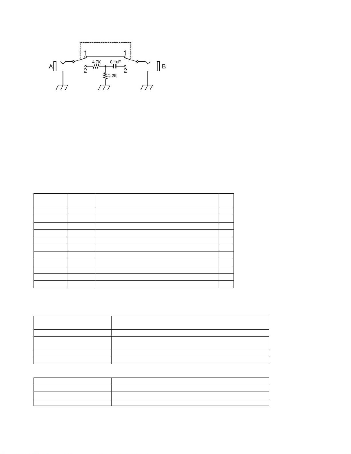
SYNC TEST JIG SCHEMATIC
Oscilloscope setting.
VERTICAL: CH1 500mV/DIV, DC coupling
HORIZONTAL: 2.5mS/DIV
How to start test mode
Turn on the power while holding down the [Play],[Rec] and [VCO2] button.
Summary of the test mode
There is a [stand-by state] and [test execution state] state at the time of inspection.
Usually it is in [test execution state], but it is in standby mode by interrupting the test all the LED blinks
when an error occurs during the inspection.
With the exception of the error display and LED inspection, inspection number is displayed on the
7-segment LED.
Test Mode Introduction
Inspection
Number
Display inspection
item
0 0. * Internal inspection(Pin,ROM,Panel)
1 1. * LED and button check
2 2. * Rotary switch check *1)
3 3. * AD and knob inspection
4 4. * Synchronization function inspection
5 5. * Audio check *1)
6 6. * Audio PCB inspection *1)
7 7. * Battery inspection *1)
8 8. * Checking the tuner function *1)
14 14. * Electrostatic sensor display *1)
15 15. * Power off test *1)
*1) This test is not required.
Test Mode Operation
Operation in the [test execution state] state
[VCO1]+[VCO3] button Exiting the test running and return to the previous
inspection.
[VCO1]+[FUNC] button Exiting the test running and proceed to the next inspection.
[VCO1]+[VCO2] button Exiting the test running and change to standby mode
[VCO3] button Return to the previous step.
[FUNC] button Skip to the next step.
.
Operation in the standby state
[VCO3] button It returns to the previous inspection keep standby.
[FUNC] button It proceeds to the next inspection keep standby.
[VCO2] button To start the inspection in stand-by state
[VCO1]+[VCO2]button error contents display