Precautions
(1) Use the push button switch for both positive and negative (KASUGA ELECTRIC WORKS LTD. BSW-330B). (This cannot be
used for RES-4024, RES-7524.)
(2) Use N120-H of GS or equivalent for the battery.
(3) If the battery charge has become low and load is given to the motor (i.e. larger electricity flows), the voltage will decrease
extremely. Charge the battery or replace it with a new one. If you use a battery with a low charge, excess current will flow at
startup, which may cause the voltage to decrease. As such, the brake will not open nor will the motor rotate, which may
result in burnout. To avoid such events, always check the battery charge. Charge the battery if the voltage drops by 3 V or
more at startup. It drops by only 0.4 V for a new or freshly charged battery.
(4) Use a power supply cord with a diameter of 5.5mm2.
(5) Be sure to use a safety breaker and fuse to protect the motor. (For safety breaker, we recommend Tempearl Industrial Co.,
Ltd.'s wiring breaker.)
(1) CAUTIONARY INSTRUCTIONS
1) Use a push-button switch of forward-stop-reverse type.
2) Use a GS battery of N120H or an equivalent.
3) When battery capacity is lowered charge or replace the battery with a new one as the voltage drops extremely when load is
applied to the motor. Please pay attention to battery capacity at all times. Perform charging if the voltage drops more than 3V
at start-up. With a new battery, voltage drop is up to 0.4V only.
4) Use 5.5mm2wires (cords) of 6 cores between the push-button switch and the motor lead wires and 5.5mm2wires of 2 cores
between the battery and the motor lead wires.
5) Be sure to use safety breakers and fuses to protect the motor.
6) Refrain from extending the wire over 10 m as far as possible. If longer extension is necessary, use a wire of 5.5mm2or larger.
7) Connect the solderless terminals firmly with screws and nuts. Loose fastening can generate heat and may cause burning.
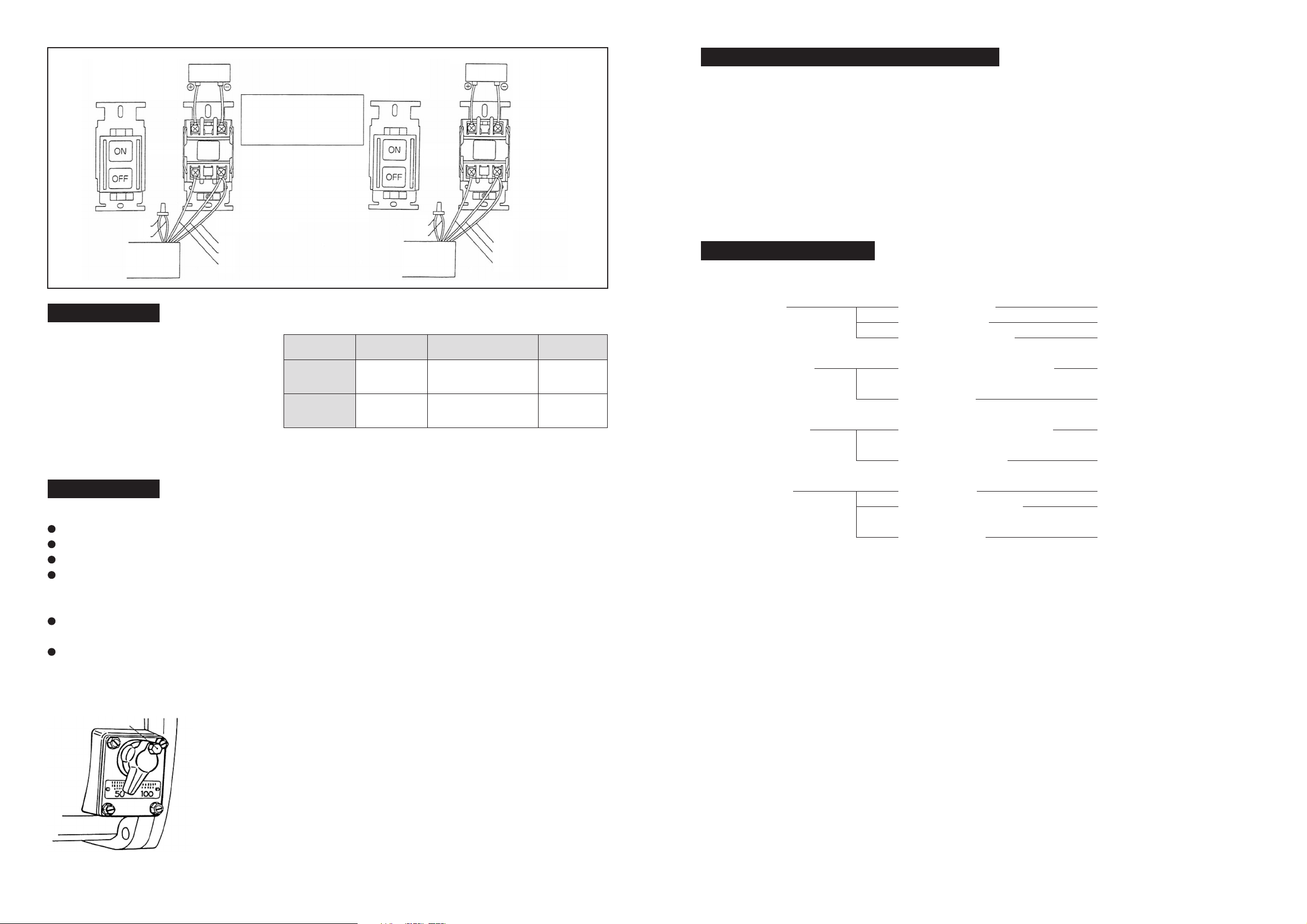
(2) CONNECTING METHOD
Open the upper cover of the push-button switches, then the terminals blocks T,S,R,W,U and V are exposed as shown in the
above drawing.
1) Connect R terminal block of the push-button switch (the switch in the following text) with red lead wire of the motor.
2) Connect S terminal block of the switch with yellow lead wire of the motor.
3) Connect T terminal block of the switch with black lead wire of the motor.
4) Connect V terminal block of the switch with green lead wire of the motor and also connect the wire from V terminal block of
the switch to the wire from negative (-) side of the battery.
5) Connect U terminal block of the switch with blue lead wire of the motor.
6) Connect the wire from W terminal block of the switch with the wire from positive (+) side of the battery.
7) Insert a safety breaker into the wiring from the lead wires of the motor to the battery.
How to connect
You will find terminal blocks T, S, R, W, U, and V as shown in figure II when opening the push button switch cover.
(1) Connect terminal block R of the push button switch (hereafter referred to as "switch") using a black motor lead wire.
(2) Connect terminal block S using a red motor lead wire.
(3) Connect terminal block T using a black (white) electromagnetic break lead wire.
(4) Connect terminal block V using both a white (black) electromagnetic break lead wire and white electric wire from the positive
side of the battery.
(5) Short-circuit terminal blocks U and W and connect terminal block U with a black electric wire from the negative side of the battery.
(6) Install a safety breaker in the electric wire from the motor lead wire to the battery. If you press the positive side of the switch,
the roller operates clockwise from the roller side; and if you press the negative, it does counterclockwise.
(6) Avoid as much as possible using an electric wire over 10m long. If necessary for use, use a wire with a diameter of 8.0mm2or more.
(7) Connect firmly between crimp terminals using screws and nuts. Loose connections may generate heat and result in burnout.
3 4
WRITING
Magnet motor type
Simultaneous use of both positive and negative rotation
RES-5524LB , RES-7524
RES-4024
*Since RES-4024 does not have a break,
wiring for the electromagnetic break lead wire can be omitted.
WHEN USED FOR BOTH FORWARD AND REVERSE TURN
REL-2512(L) .RES-2512(L) .4024 A view of the push-button switch with is upper cover removed.
Note:
1. (R)-(T) (*)-(V) is also available for electromagnetic break cord connection.
2. Short-circuit between switches (W) and (U).
Red
Black
Black
White
White
Positive (+) side
Negative
(-) side
Black
Battery
T
V
R
SV
VU
U
Load
Breaking current
200kg
40A
400kg
60A
600kg
80A
Load
Shut-off current
RES-4012
90kg (100rpm)
180kg (50rpm)
60A
130kg (100rpm)
260kg (50rpm)
80A
Load
Breaking current
200kg
40A
400kg
60A
600kg
80A
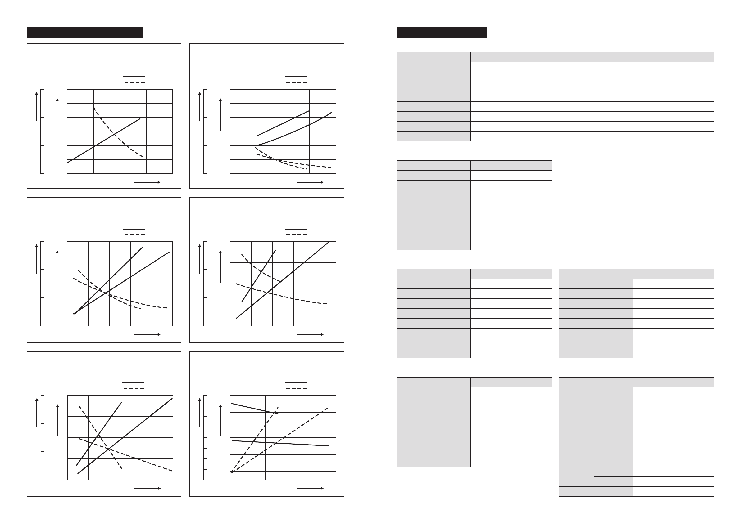
(See the performance curve for more details.)
Lead wires
of the motor
Black
Black
White
White
Safety breaker
Positive
(+) side
Negative
(-) side
Battery
1
2
3
4
5
1 Black
Green
Blue
Red
Yellow
2
3
4
5
Lead-wire for
Electromagnetic Brake
Lead-wire for Motor
Motor (Black) - Switch
Motor (Black) - Switch
- Switch
- Switch
Battery - Switch
Battery - Switch
Switch - Switch
R
R
V
T
V
U
U
Safety Breaker