3 4
ExternalOptions
forSWL
SWLZ
Robotic
HandChanger
SWL
RoboticHandChanger modelSWL Features
SelectionConditions
ReferenceDocument
Accessories
ExternalOptions
Cautions
CrossSection
ActionDescription
ModelNo.
Indication
External
Dimensions
Specifications
PerformanceCurve
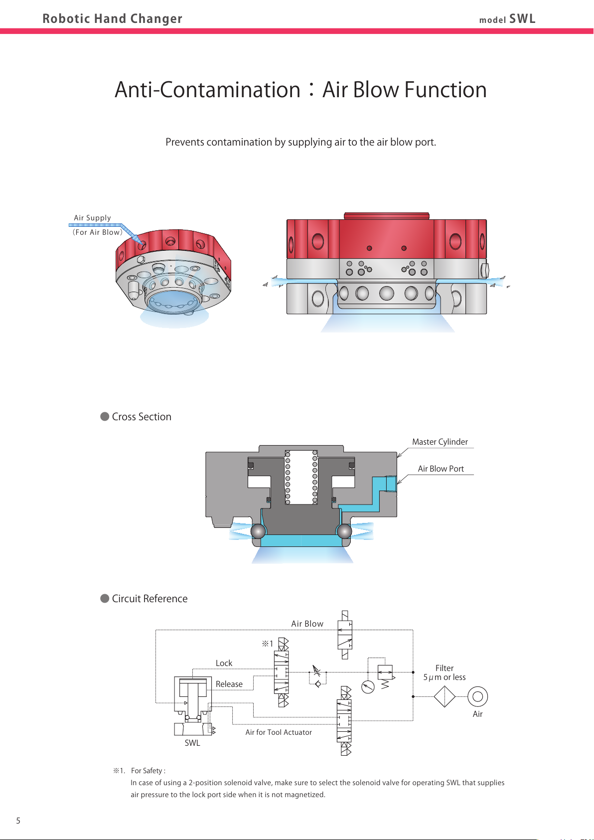
CrossSection
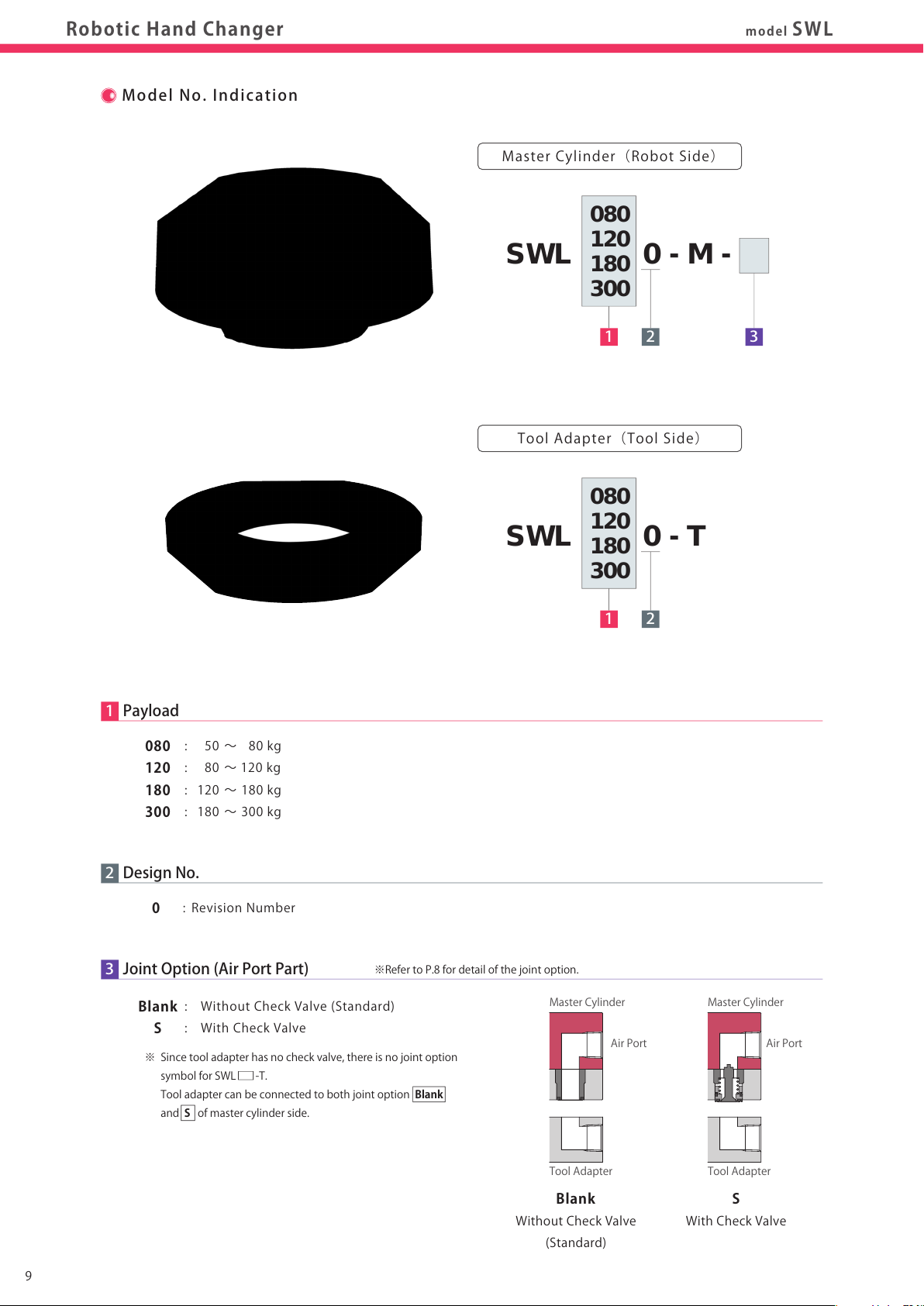
MasterCylinder(SWL
□
0-M)
ToolAdapter(SWL
□
0-T)
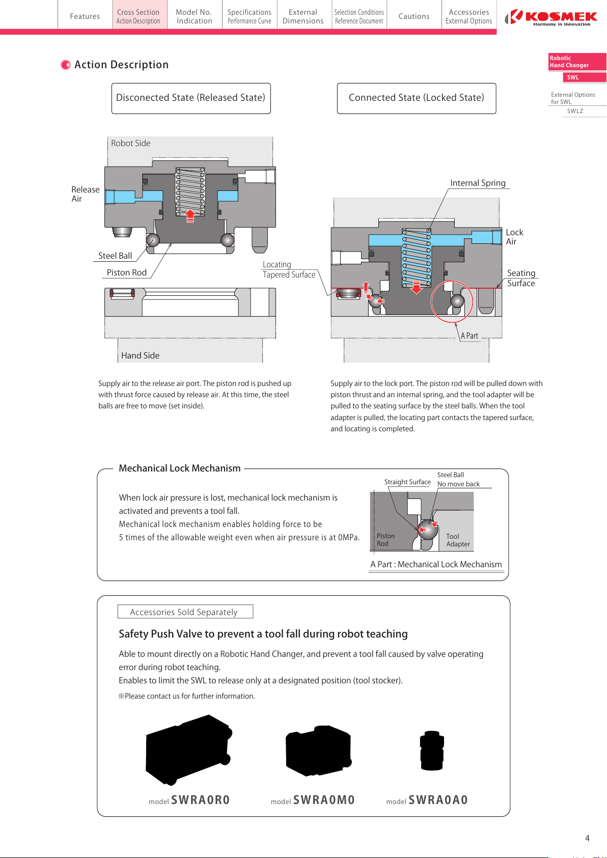
DisconectedState(ReleasedState)ConnectedState(LockedState)
ActionDescription
AirBlowPort
RoughGuide
SeatingConfirmationPort
LockAirPort
Locatingpart(2parts)
TaperSleeve(2parts)
ElasticRing
ReleaseAirPort RobotSide
Release
Air
SteelBall
InternalSpring
SteelBall
Nomoveback
StraightSurface
PistonRod
Lock
Air
HandSide
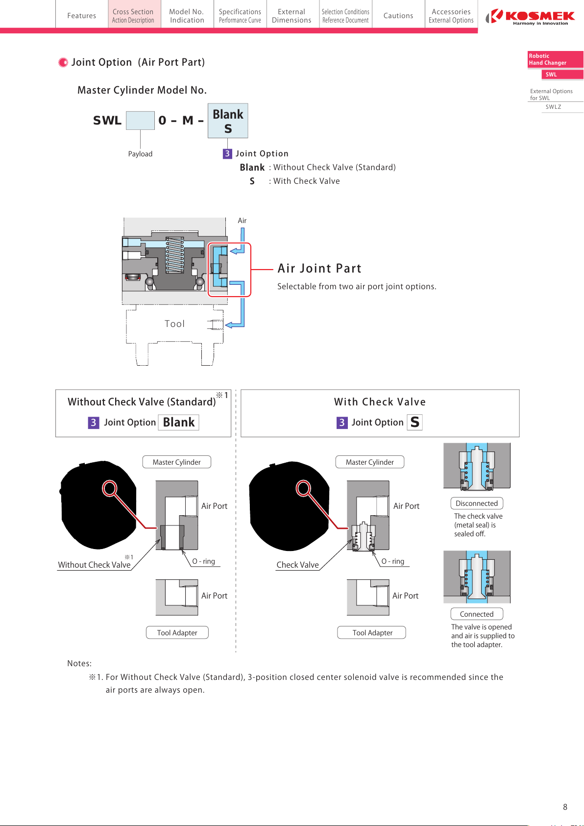
Supplyairtothelockport.Thepistonrodwillbepulleddownwith
pistonthrustandaninternalspring,andthetooladapterwillbe
pulledtotheseatingsurfacebythesteelballs.Whenthetool
adapterispulled,thelocatingpartcontactsthetaperedsurface,
andlocatingiscompleted.
APart
Material:StainlessSteel
(HighHardnessbyHeatTreatment)
Material:Duralumin
AirBlow-outHoleforSeatingConfirmation
Whenlockairpressureislost,mechanicallockmechanismis
activatedandpreventsatoolfall.
Mechanicallockmechanismenablesholdingforcetobe
5timesoftheallowableweightevenwhenairpressureisat0MPa.
APart:MechanicalLockMechanism
Tool
Adapter
Piston
Rod
MechanicalLockMechanism
SafetyPushValvetopreventatoolfallduringrobotteaching
AirPort(4ports)
AirPort(4ports)
Seating
Surface
AbletomountdirectlyonaRoboticHandChanger,andpreventatoolfallcausedbyvalveoperating
errorduringrobotteaching.
EnablestolimittheSWLtoreleaseonlyatadesignatedposition(toolstocker).
※Pleasecontactusforfurtherinformation.
modelSWRA0M0modelSWRA0R0 modelSWRA0A0
Locating
TaperedSurface
Supplyairtothereleaseairport.Thepistonrodispushedup
withthrustforcecausedbyreleaseair.Atthistime,thesteel
ballsarefreetomove(setinside).
AccessoriesSoldSeparately
Material:StainlessSteel
(HighHardnessbyHeatTreatment)