9
JES
WPT
SensorforAirCylinder
High-Power
PullStudClamp
modelWPTHigh-PowerPullStudClamp Cautions
Performance
Curve
External
Dimensions
Installation
Method
Accessory
SensorforAirCylinder
Cautions
ModelNo.
Indication
Specifications
FeaturesFeatures
●NotesforDesign
1) CheckSpecifications
●ModelWPT:Maximumoperatingairpressureis0.5MPa.
Minimumoperatingairpressureis0.3MPa.
ApplyingexcessiveloadonthePullStudClampleadsto
deformation,gallingandairleakage.
2) Donotapplyimpactonaworkpiece,etc.connectedtoPullBolt.
●Otherwise,itmayresultinbreakageoftheproduct.
3) NotesforCircuitDesign
●Pleasedesigntheaircircuitproperlyandreviewthecircuit
designinadvanceinordertoavoidmalfunctionorbreakage
ofthedevice.
4) Pleasesupplyfilteredcleandryair.
●Oilsupplywithalubricatoretc.isunnecessary.
5) OperatingEnvironment
●WPThasnofunctionthatpreventscontaminants.
Donotuseunderenvironmentwithcoolantandcuttingchips.
6) InsertionofPullBolt
●PleaseinsertthePullBolttotheendbeforeprovidinglockair
pressure.(PreventionofclampingfailureanddamageofPullBolt.)
7) ProtectiveCoverInstallation
●Ifthemovingpartsoftherobotorrobotichandmayendanger
operator,pleaseinstalltheprotectioncover.
8) FallPreventionMeasures
●Incaseofaccidentsuchasdetachmentofaworkpiece,
pleasepreparefallpreventionmeasuresforsafety.
1) UsableFluid
●Pleasesupplyfilteredcleandryair.(Installadrainremovingdevice.)
●Oilsupplywithalubricatoretc.isunnecessary.Oilsupplywith
alubricatormaycauselossoftheinitiallubricant.Theoperation
underlowpressureandlowspeedmaybeunstable.(Whenusing
lubricant,pleasesupplylubricantoilcontinuously.Otherwise,
theinitialgreaseappliedbyKOSMEKwillberemoved.)
2) ProcedurebeforePiping
●Thepipeline,pipingconnectorandfixturecircuitsshouldbe
cleanedandflushedthoroughly.
Thedustandcuttingchipsinthecircuitmayleadtoairleakage
andmalfunction.
●Thereisnofilterprovidedwiththisproductforpreventionof
contaminantsintheaircircuit.
3) ApplyingSealingTape
●Whenusingsealingtape,wrapwithit1to2timesfollowing
thescrewingdirection.Whenpiping,becarefulthatcontaminant
suchassealingtapedoesnotenterinproducts.
Piecesofthesealingtapecancauseairleakageandmalfunction.
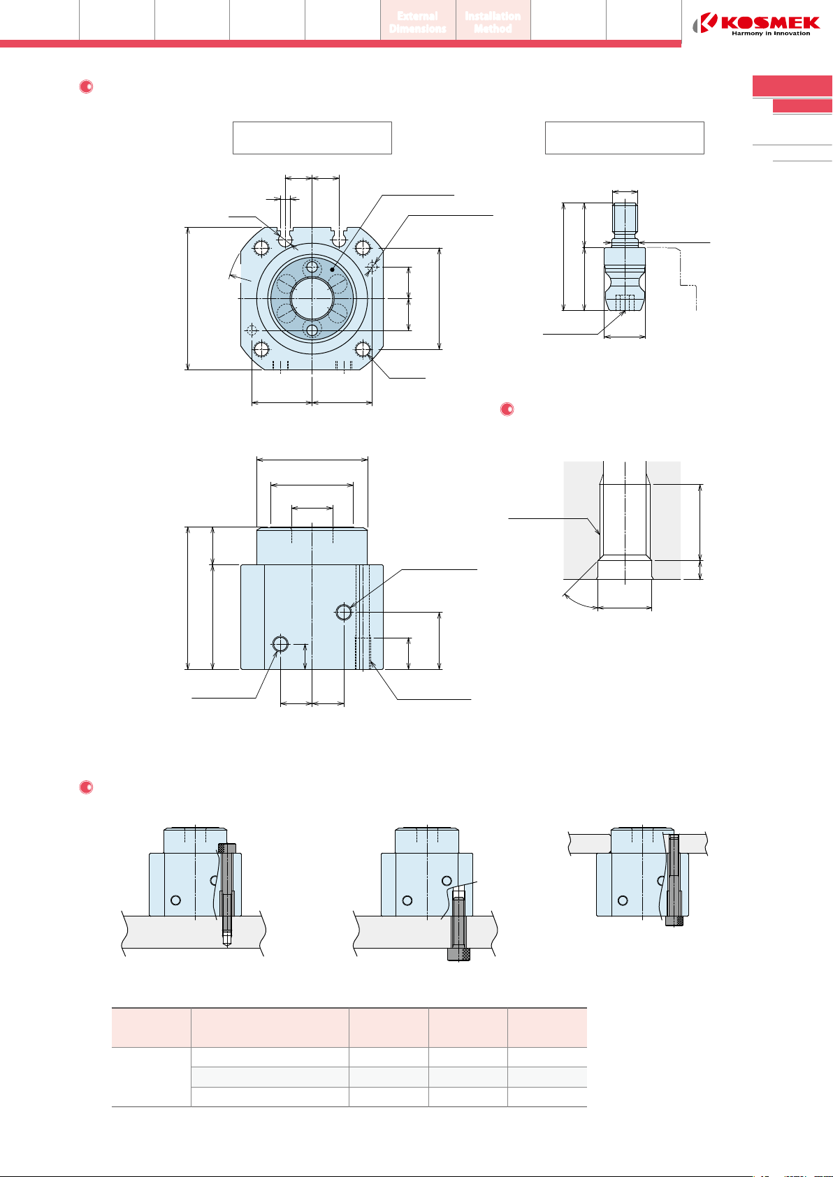
4) InstallationoftheMainBodyandthePullBolt
●Pleaseusehexagonsocketbolts(withtensilestrengthofA2-70
orgreater),andtightentheproductwiththetighteningtorque
listedonP.5~P.8.
●Thetighteningtorqueforpullboltisshownbelow.
●Installationfailurecausesairleakage,deformationanddamage
ofthePullStudClampandthePullBolt.
5) DoNotUseDeformedPullBolts
●IfaPullBoltisdeformedasshownbelow,PullStudClampand
PullBoltwillbebroken,and/orwillnotbeabletoreleaseproperly.
●InstallationNotes
Cautions
6) AllowableOffsetwhileClamping
●Whileclamping,thegapbetweentheseatingsurfacesofthe
PullStudClampandaworkpiece,etc.shouldbe0.2mmorless.
Atthistime,insertthePullStudClampverticaltothePullBolt.
Afterclamping,thePullBoltispulledinandtheseatingsurfaces
andworkpiececomeincontact.
●AllowablepositionoffsetofPullStudClampandPullBoltwhile
teachingmustbewithintheallowablepositionoffsetrange.
Atthistime,thechangingworkpieceshouldnʼtbecompletely
fixedandshouldhavespacewithintherangeofallowableoffset.
AllowablePositionOffsetinHorizontalDirection
ModelNo.
WPWZ500-P1
WPWZ600-P1
WPWZ800-P1
WPWZ1000-P1
BoltSize
M4×0.7
M5×0.8
M6×1
M8×1.25
TighteningTorque(N・m)
2.3
4.0
9.0
18
ModelNo.
WPT0500
WPT0600
WPT0800
WPT1000
AllowableOffsetAmm
A=±0.5mm
A=±0.7mm
A=±0.8mm
A=±0.9mm
0.2mmorless
NoGap
Workpiece
SeatingSurface
PullStudClamp
SeatingSurface
InsertVertically BeforeClamping AfterClamping
A
PullStud
Clamp
PullBolt