manuals.online logo
Brands
  1. Home
  2. •
  3. Brands
  4. •
  5. Kostal
  6. •
  7. Inverter
  8. •
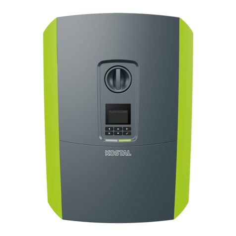
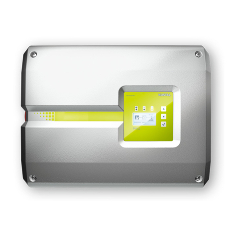
  9. Kostal PLENTICORE plus Instruction Manual

Kostal PLENTICORE plus Instruction Manual

Seite 1 / 12 DOC_Guide_PLENTIOCRE_BYD_ 2019-04-17-FW_1.20_EN
Guideline
Commissioning PLENTICORE plus inverter in
combination with a BYD Battery-Box HV H5.1 -
H11.5
This guide does not replace the operating instructions or manuals required for proper assembly and installation.
The trademarks, trade names, product descriptions and other designations used may be protected by law even without special
designation (e.g. as trademarks). KOSTAL Solar Electric GmbH does not assume any liability or warranty for their free usability.
Great care has been taken in the compilation of illustrations and texts. Nevertheless, errors cannot be excluded. The compilation
is made without guarantee. Technical changes and errors excepted
.
Seite 2 / 12 DOC_Guide_PLENTIOCRE_BYD_ 2019-04-17-FW_1.20_EN
IMPORTANT INFORMATION
Installation may only be carried out by a trained and qualified electrician!
Observe the safety instructions in the operating instructions for the inverter and
the battery.
In order to start up the system completely and to make all necessary settings,
the Service/PARAKO password and a computer/tablet as well as the battery
activation code are required.
The inverter and the battery must be completely disconnected from the voltage supply for all work on the inverter
or on the supply lines. Refer to the relevant operating instructions for the respective devices (inverter/battery).
Install PLENTICORE plus inverter, connect AC cables and control cables but DO
NOT start up yet.
DO NOT yet connect the DC plug of the PV strings to the inverter.
Connect DC cable, connect ground cable, connect RS485 cable to the BCU and to
the SCB of the WR, but DO NOT yet put into operation.
DO NOT yet connect the DC plug of the battery to the inverter.
Install the Energy Meter or Energy Manager and connect the RS485 cable to the SCB
of the inverter.
Establish LAN connection between inverter and router (customer network).
Connection of the RS485 cable of the Energy Meter or Energy Manager with the SCB (X452) of
the PLENTICORE plus inverter.
Seite 3 / 12 DOC_Guide_PLENTIOCRE_BYD_ 2019-04-17-FW_1.20_EN
The Modbus RTU interface (A) is preconfigured as standard with the readout intervals
for the PLENTICORE plus or PIKO IQ inverters.
The KOSTAL Smart Energy Meter can be installed directly in the sub-distribution
cabinet and connected to the inverter without a PC (adjustment of parameters) and
other settings. The device is immediately ready for use.
ATTENTION: The B-control EM300 LR and the KOSTAL Smart Energy Meter
have different RS485 pin connections.
Seite 4 / 12 DOC_Guide_PLENTIOCRE_BYD_ 2019-04-17-FW_1.20_EN
X601 on the SCB in PLENTICORE plus inverter.
Position of jumper, it must be plugged
to JP2, newer BCU devices have two
jumpers plugged to (JP1 and JP2).
Connection of the RS485 cable of the BCU from the BYD Battery-Box HV to the SCB (X601) of
the PLENTICORE plus inverter.
Configuring the BCU of the BYD Battery-Box HV via WLAN
Activating the WLAN on the computer
Select the BYD battery from the list of devices in the WLAN network
Enter the network key for the WIFI of the BYD battery access: 123456789
In the URL field of the browser now enter the IP of the BCU: 192.168.5.1
A login window will open
Enter username: installer and password: byd@12345 and confirm
The web server opens with the "HOME" page
Click on "Installation" in the menu
The "Installation" window opens
All necessary values for the configuration are now entered here
Seite 5 / 12 DOC_Guide_PLENTIOCRE_BYD_ 2019-04-17-FW_1.20_EN
The time and date must be entered.
Then click on the "Next" button.
Series Battery Counts - Enter number of memory modules - 4 to 9
Inverter - Select inverter manufacturer - KOSTAL
Country - Select your country –e.g. Germany
Finally click on the "Finish" button.
The battery system restarts and is ready for operation.
Seite 6 / 12 DOC_Guide_PLENTIOCRE_BYD_ 2019-04-17-FW_1.20_EN
Initial commissioning of the PLENTICORE plus inverter
Attention: Commissioning only possible with sufficient PV voltage and irradiation.
Check the RS485 connection Energy Meter to the SCB of the inverter.
Plug in the DC plug of the PV strings.
Connect the DC plug of the battery.
Switch on AC fuses.
Switch on DC Switch.
The start-up process of the inverter has started.
The installation assistant appears in the inverter display.
Commissioning can be carried out completely via the display.
Simply follow the instructions on the display.
Alternatively, the commissioning can also take place partly via the web server.
oSelect language, date and country in the display.
oActivate IPv4 / DHCP in the display
oSelect e.g. the NSR Germany country code in the display and complete the
installation.
Make all other settings on the web server of the inverter.
Read IP address from inverter display.
Enter the IP of the inverter into the URL line of your browser e.g. Mozilla or Firefox.
The login window will open.
Seite 7 / 12 DOC_Guide_PLENTIOCRE_BYD_ 2019-04-17-FW_1.20_EN
All other settings can now be entered in the service menu.
Service menu Energy management: Choice of energy meter and position of the
sensor
Seite 8 / 12 DOC_Guide_PLENTIOCRE_BYD_ 2019-04-17-FW_1.20_EN
Checkbox: "Storage of excess AC energy from local generation."
This feature works with the Energy Manager from B-control, the EM300 LR
as well as with the KOSTAL Smart Energy Meter (KSEM).
IMPORTANT: The sensor (Energy Manager/Meter) must be mounted in the
"Mains connection point" position.
Activate reception of Broacast control signals
Service menu Energy management: Activate storage of excess AC energy from
local generation.
Seite 9 / 12 DOC_Guide_PLENTIOCRE_BYD_ 2019-04-17-FW_1.20_EN
Service menu Battery settings: All settings for the connected battery made here.
Seite 10 / 12 DOC_Guide_PLENTIOCRE_BYD_ 2019-04-17-FW_1.20_EN
When all settings have been completed, the KOSTAL storage system is running. The
green LED on the inverter lights up.
The PLENTICORE plus (or PIKO IQ) is now ready for operation.
A firmware update is available: Download from our homepage
Download and install the software for the PLENTICORE plus inverter that was released/up to date at
the time of installation. This software can be downloaded from our homepage under the following link:
https://www.kostal-solar-electric.com/de-
de/download/download#PLENTICORE%20plus/PLENTICORE%20plus%2010/Deutschland/Update/
Install the software package as described in detail in the inverter operating instructions.
Seite 11 / 12 DOC_Guide_PLENTIOCRE_BYD_ 2019-04-17-FW_1.20_EN
Troubleshooting –Commissioning
EC 6006: „A parameterizable number of attempts to read a value from the sensor failed“
It indicates an error in the communication between the Energy Meter and the inverter.
Check RS485 data cable
Check pin configuration of the RS485 connector
Is the right Energy Manager/Meter selected?
Is the correct sensor position selected?
Restart the Energy Meter, use the RESET Button
EC 6009: „Five attempts to communicate with the battery system failed“.
It indicates an error in the communication between the inverter and the battery.
Is the BCU ground correctly connected to Equipotential bonding rail?
Check RS485 data cable
Check pin configuration of the RS485 connectors
Is the battery correctly configured?
Check position of jumper, must be plugged in to 2, newer BCU devices have two
jumpers plugged in (to 1 and 2)
EC 5095: „The inverter cannot measure the battery voltage at DC input 3”
With this message no voltage is detected at the DC3 input of the WR from the battery.
Is the battery on the circuit breaker switched on?
Is an error displayed on the battery's web server?
Is the polarity of the DC cables from the battery OK?
Is the battery correctly configured?
The battery is OK and shows no error. In this case, restart the PLENTICORE plus
inverter. Restart sequence: Switch off the device at the DC switch, switch off AC fuses,
remove DC strings and wait 2 minutes. Then plug in the DC strings, switch on the AC
fuses and switch on the DC switch again. The device restarts. The EC should no longer
be present and the battery has been detected and is in operation.
Further information and help
Link to the KOSTAL download page:https://www.kostal-solar-electric.com/de-
de/download/download
Link to the EFT Software download page: https://www.eft-systems.de/de/downloads
Please register the inverter to receive the 5 year warranty.
Link to registration: https://shop.kostal-solar-electric.com/de/kostal-smart-warranty.html
Seite 12 / 12 DOC_Guide_PLENTIOCRE_BYD_ 2019-04-17-FW_1.20_EN
Basic information by communication problems
Experience has shown that switches or WLAN repeaters that do not support multicasting or do not
properly process and distribute multicast packets (keywords: IPTV, network printer, IP camera, etc.)
are often installed in the event of communication problems.
It must therefore be ensured that the communication interfaces of the PV system are not disturbed in
any way.
If multicast filtering with Internet Group Message Protocol (IGMP*) is not used, the interfaces may be
overloaded because they must respond permanently to multicast traffic that is not intended for them.
Please note that KOSTAL cannot provide detailed recommendations for suitable network devices or
support for the network architecture.
If you are using a Telekom media receiver that is to be connected via WLAN, powerline or switch, you
will find a list of working combinations in the official Telekom Helps Community:
https://telekomhilft.telekom.de/t5/Fernsehen/EntertainTV-neu-Liste-funktionierender-Kombinationen-
mit-WLAN/td-p/1867188
Please consult your network specialist or provider if you need further assistance.
*Note: The current IGMP version 3 is used e.g. for the provision of the IP-TV service "Entertain" of
Deutsche Telekom.
In addition, the following points must be observed to ensure interference-free and secure data
transmission:
1. Signal, data and communication lines must be strictly separated from power cables. Pay
attention to separators in cable ducts.
2. Only use cables and wires for data transmission that are approved and/or suitable for this
purpose.
3. The inverter (additional grounding on the casing frame) and the battery (grounding of the
BMS) must be at exactly the same ground potential. Determine the low resistance of the
individual protective conductors by means of a measurement. Only if the battery and the
inverter are properly grounded can trouble-free and reliable data transmission be guaranteed.

Other manuals for PLENTICORE plus

4

This manual suits for next models

2

Other Kostal Inverter manuals

Kostal PIKO CI User manual

Kostal

Kostal PIKO CI User manual

Kostal PIKO 10-20 User manual

Kostal

Kostal PIKO 10-20 User manual

Kostal PIKO 36 EPC How to use

Kostal

Kostal PIKO 36 EPC How to use

Kostal PIKO MP plus User manual

Kostal

Kostal PIKO MP plus User manual

Kostal PIKO Series User manual

Kostal

Kostal PIKO Series User manual

Kostal PIKO CI How to use

Kostal

Kostal PIKO CI How to use

Kostal PLENTICORE plus G2 User manual

Kostal

Kostal PLENTICORE plus G2 User manual

Kostal PIKO 3.0 User manual

Kostal

Kostal PIKO 3.0 User manual

Kostal PLENTICORE BI How to use

Kostal

Kostal PLENTICORE BI How to use
Kostal PIKO MP plus series User manual

Kostal

Kostal PIKO MP plus series User manual

Kostal PLENTICORE plus User manual

Kostal

Kostal PLENTICORE plus User manual

Kostal PIKO MP plus 1.5-1 Manual

Kostal

Kostal PIKO MP plus 1.5-1 Manual

Kostal PIKO 6.0 BA How to use

Kostal

Kostal PIKO 6.0 BA How to use

Kostal PIKO Inverter 3.0 How to use

Kostal

Kostal PIKO Inverter 3.0 How to use

Kostal PIKO 10 User manual

Kostal

Kostal PIKO 10 User manual

Kostal PLENTICORE plus How to use

Kostal

Kostal PLENTICORE plus How to use
Kostal PLENTICORE plus User manual

Kostal

Kostal PLENTICORE plus User manual

Kostal PIKO User manual

Kostal

Kostal PIKO User manual

Kostal PLENTICORE BI User manual

Kostal

Kostal PLENTICORE BI User manual

Kostal PIKO 4.2 User manual

Kostal

Kostal PIKO 4.2 User manual

Kostal PLENTICORE plus G2 User manual
Kostal

Kostal PLENTICORE plus G2 User manual

Kostal PLENTICORE plus How to use

Kostal

Kostal PLENTICORE plus How to use

Kostal PIKO CI User manual

Kostal

Kostal PIKO CI User manual

Kostal PIKO IQ How to use

Kostal

Kostal PIKO IQ How to use

Popular Inverter manuals by other brands

Ego Power+ Nexus Escape Operator's manual

Ego Power+

Ego Power+ Nexus Escape Operator's manual

BRUEL & KJAER 1024 Service instructions

BRUEL & KJAER

BRUEL & KJAER 1024 Service instructions

Fortinet FortiToken-200B quick start guide

Fortinet

Fortinet FortiToken-200B quick start guide

Selectronic Australia LD550-24 operating manual

Selectronic Australia

Selectronic Australia LD550-24 operating manual

YASKAWA VS mini C Series instruction manual

YASKAWA

YASKAWA VS mini C Series instruction manual

Sungrow SG15KTL-M Quick installation guide

Sungrow

Sungrow SG15KTL-M Quick installation guide

SDMO R44C3 User and maintenance manual

SDMO

SDMO R44C3 User and maintenance manual

LIVOLTEK GT3-17K-D user manual

LIVOLTEK

LIVOLTEK GT3-17K-D user manual

LIFE SOLAR LSH5004826 user manual

LIFE SOLAR

LIFE SOLAR LSH5004826 user manual

ABB MICRO-0.25-I-OUTD-US-208/240 product manual

ABB

ABB MICRO-0.25-I-OUTD-US-208/240 product manual

LSIS LSLV-S100 Series Operation manual

LSIS

LSIS LSLV-S100 Series Operation manual

SMA SUNNY BOY 1.5 operating manual

SMA

SMA SUNNY BOY 1.5 operating manual

ECTIVE CSI30 Installation and operating instructions

ECTIVE

ECTIVE CSI30 Installation and operating instructions

Smittybilt 2600i user manual

Smittybilt

Smittybilt 2600i user manual

VOLTWORKS VS-3000QBR user manual

VOLTWORKS

VOLTWORKS VS-3000QBR user manual

ABB UNO-DM-3.3-TL-PLUS-US-Q Quick installation guide

ABB

ABB UNO-DM-3.3-TL-PLUS-US-Q Quick installation guide

INVT Goodrive 35 Series Operation manual

INVT

INVT Goodrive 35 Series Operation manual

Energenie EG-PWC-001 user manual

Energenie

Energenie EG-PWC-001 user manual

manuals.online logo
manuals.online logoBrands
  • About & Mission
  • Contact us
  • Privacy Policy
  • Terms and Conditions

Copyright 2025 Manuals.Online. All Rights Reserved.