manuals.online logo
Brands
  1. Home
  2. •
  3. Brands
  4. •
  5. Kostal
  6. •
  7. Inverter
  8. •
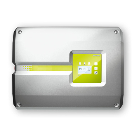
  9. Kostal PIKO CI User manual

Kostal PIKO CI User manual

Activate EXTRA YEARS
of FREE WARRANTY!
at shop.kostal-solar-electric.com
Quick Start Guide
PIKO CI
Weitere Informationen zum Wechselrichter wie z. B. eine ausführliche
Betriebsanleitung, freigegebene Energiezähler, Ländereinstellungen
für die Inbetriebnahme, freigegebene Länder in denen der Wechsel-
richter betrieben werden kann, Service- und Garantiebedingungen,
EU-Konformitätserklärung und Zertifikate finden Sie im Internet im
Downloadbereich zu Ihrem Produkt unter
www.kostal-solar-electric.com > Download.
Further information on the inverter, such as detailed operating
instructions, approved energy meters, country settings for commis-
sioning, approved countries in which the inverter can be operated,
service and guarantee conditions, EU declaration of conformity and
certificates can be found on the Internet in the download area for
your product under
www.kostal-solar-electric.com > Download.
DE Gefahr! Lebensgefahr durch Stromschlag und elektrische Entladung. Im Wechselrichter liegen lebensgefährliche Spannungen an. Nur eine Elektrofachkraft
darf das Gerät önen und daran arbeiten. Gerät bei Montage, Wartung und Reparaturen immer spannungsfrei schalten und gegen Wiedereinschalten sichern.
Die PV-Generatoren/-Leitungen können unter Spannung stehen, sobald diese dem Licht ausgesetzt sind. Im laufenden Betrieb dürfen keine DC-Leitungen
an das Gerät angeschlossen oder abgezogen werden, da gefährliche Lichtbögen entstehen können. Die Firma KOSTAL Solar Electric GmbH erklärt hiermit,
dass sich die in diesem Dokument beschriebenen Wechselrichter mit den grundlegenden Anforderungen und anderen relevanten Bestimmungen der unten
genannten Richtlinien in Übereinstimmung befinden.
EN Danger! Risk of death due to electrical shock and discharge. Life-threatening voltages are present in the inverter. Only a qualified electrician may open and perform work on the
device. Always de-energise the device during installation, maintenance and repairs, and secure it against being switched back on. The PV generators/cables may be live as soon
as they are exposed to light. DC cables must never be connected to or disconnected from the device during operation, as dangerous arcs may form. KOSTAL Solar Electric GmbH
hereby declares that the inverter described in this document complies with the basic requirements and other relevant conditions of the directives listed below.
ES ¡Peligro! Peligro de muerte debido a electrocución y descarga eléctrica. En el inversor existen tensiones que pueden poner en peligro su vida. Únicamente se permite abrir el
equipo y realizar trabajos en el mismo a electricistas profesionales. Durante el montaje, el mantenimiento y reparaciones, desconecte siempre el equipo de la tensión y protéjalo
contra reconexión. Las líneas y los generadores fotovoltaicos pueden estar bajo tensión tan pronto como quedan expuestos a la luz. Mientras el equipo esté en funcionamiento,
queda prohibido conectar o desconectar cables CC del mismo, puesto que pueden producirse arcos eléctricos peligrosos. La empresa KOSTAL Solar Electric GmbH declara por
el presente que los inversores descritos en este documento cumplen los requisitos básicos y otras disposiciones relevantes de las directivas indicadas abajo.
FR Danger ! Danger de mort par électrocution et décharge électrique. Des tensions représentant un danger mortel traversent l’onduleur. Seul un électricien est habilité à ouvrir
l’appareil et à y eectuer des travaux. Lors de l’installation, de l’entretien et de la réparation, mettre toujours l’appareil hors tension et le protéger contre toute remise en marche.
Les générateurs ou les câbles photovoltaïques peuvent être sous tension dès qu’ils sont exposés à la lumière. Ne pas brancher ni débrancher les câbles DC de l‘appareil pendant
son fonctionnement au risque de créer des arcs électriques dangereux. La société KOSTAL Solar Electric GmbH certifie par la présente déclaration que les onduleurs décrits dans
le présent document sont conformes aux exigences fondamentales et aux autres dispositions applicables des directives ci-dessous.
IT Pericolo! Pericolo di morte per scossa elettrica e folgorazione. Nell‘inverter si trovano tensioni mortali. Solo un elettricista specializzato può aprire il dispositivo e operare su di
esso. Durante l’installazione, la manutenzione o la riparazione, togliere sempre la tensione al dispositivo e impedirne la riaccensione. I generatori / i cavi dell‘impianto FV possono
essere in tensione quando il campo fotovoltaico è irradiato. Durante il funzionamento, i cavi DC non devono essere collegati o scollegati dal dispositivo, poiché potrebbero verificarsi
pericolosi archi elettrici. La società KOSTAL Solar Electric GmbH dichiara con la presente che gli inverter descritti nel presente documento soddisfano i requisiti fondamentali e le
altre disposizioni rilevanti delle direttive sotto indicate.
Legal notice
KOSTAL Solar Electric GmbH
Hanferstraße 6, 79108 Freiburg i. Br., Germany, Phone +49 (0)761 477 44 - 100, www.kostal-solar-electric.com.
Exclusion of liability
All names, trademarks, product names or other designations given in this manual may be legally protected even if this is not labelled
as such (e.g.as a trademark). KOSTAL Solar Electric GmbH accepts no liability and gives no assurance that they can be freely used.
The illustrations and texts have been compiled with great care. However, the possibility of errors cannot be ruled out. The compilation
is made without any guarantee.
General note on gender equality
KOSTAL Solar Electric GmbH is aware of the importance of language with regard to the equality of women and men and always
makes an eort to reflect this in the documentation. Nevertheless, for the sake of readability we are unable to use non-gender-specific
terms throughout and use the masculine form instead.
© 2023 KOSTAL Solar Electric GmbH
All rights reserved by KOSTAL Solar Electric GmbH, including those of reproduction by photocopy and storage in electronic media.
Commercial use or distribution of the texts, displayed models, diagrams and photographs appearing in this product is not permitted.
This manual may not be reproduced, stored, transmitted or translated in any form or by means of any medium – in whole or in part –
without prior written permission.
CZ Nebezpečí! Ohrožení života elektrickým proudem a výbojem. Ve střídači je životu nebezpečné napětí. Přístroj smí otevřít a pracovat na něm pouze kvali-
fikovaný elektrikář. Přístroj se musí při montáži a opravách vždy odpojit od napětí a zabezpečit proti opětovnému zapnutí. FV generátory/rozvody mohou být
pod napětím, pokud jsou vystaveny světlu. Za probíhajícího provozu nelze k přístroji připojovat stejnosměrné rozvody ani je odpojovat, protože může vzniknout
nebezpečný elektrický oblouk. Firma KOSTAL Solar Electric GmbH tímto prohlašuje, že střídače popsané v tomto dokumentu vyhovují základním požadavkům
a ostatním relevantním ustanovením níže uvedených směrnic.
EL Κίνδυνος! Κίνδυνος θανάτου από ηλεκτροπληξία και ηλεκτρική εκφόρτιση. Στον αντιστροφέα υπάρχουν θανατηφόρες ηλεκτρικές τάσεις. Το άνοιγμα της συσκευής και οι
εργασίες στη συσκευή επιτρέπεται να διενεργούνται μόνο από ηλεκτρολόγο. Πριν από την εγκατάσταση, τη συντήρηση και τις επισκευές θα πρέπει πάντα να διακόπτετε την
ηλεκτρική τροφοδοσία της συσκευής και να την ασφαλίζετε από επανενεργοποίηση. Οι Φ/Β αγωγοί/γεννήτριες μπορεί να βρίσκονται υπό τάση όταν εκτίθενται σε φως. Σε
κατάσταση λειτουργίας δεν επιτρέπεται σε καμία περίπτωση να συνδέονται ή να αποσπώνται αγωγοί DC από τη συσκευή, επειδή μπορεί να προκύψουν επικίνδυνα βολταϊκά
τόξα. Η KOSTAL Solar Electric GmbH δηλώνει με την παρούσα ότι οι αντιστροφείς που περιγράφονται σε αυτό το έντυπο συμφωνούν με τις θεμελιώδεις απαιτήσεις και άλλους
σχετικούς κανονισμούς των ακόλουθων αναφερόμενων Οδηγιών.
ET Oht! Eluohtlik elektrilöögi või elektrilahenduse tõttu. Vaheldi sisemuses on eluohtlik pinge. Seadet tohivad avada ja selle juures töid teha ainult elektrikud. Lülitage seade enne
paigaldamist, hooldust ja remonti alati pingevabaks ning kindlustage uuesti sisselülitamise vastu. Päikeseelektrigeneraatorid/-kaablid võivad pingestuda kohe, kui neile langeb
valgus. Töötava seadmega ei tohi ühendada ega töötavast seadmest lahutada alalisvoolukaableid, kuna tekkida võivad ohtlikud elektrikaared. Käesolevaga kinnitab firma KOSTAL
Solar Electric GmbH, et selles dokumendis kirjeldatud vaheldid vastavad allpool nimetatud direktiivide olulistele nõuetele ja teistele asjakohastele sätetele.
FI Vaara! Sähköiskun ja sähköpurkauksen aiheuttama hengenvaara. Invertterissä on hengenvaarallisia jännitteitä. Vain sähköalan ammattilaiset saavat avata laitteen ja tehdä sille
toimenpiteitä. Kytke laite aina jännitteettömäksi ja varmista, ettei sitä voida käynnistää uudelleen, ennen kuin asennat laitteen tai teet sille huolto- tai korjaustöitä. Aurinkopaneelit
/ aurinkosähköjärjestelmän johdot voivat olla jännitteisiä heti kun valo osuu niihin. Laitteeseen ei saa liittää eikä siitä saa irrottaa DC-johtoja käytön aikana, sillä muutoin voi syntyä
vaarallisia valokaaria. KOSTAL Solar Electric GmbH ilmoittaa, että tässä asiakirjassa kuvatut invertterit vastaavat alla mainittujen direktiivien perustavanlaatuisia vaatimuksia sekä
muita asianmukaisia määräyksiä.
NL Gevaar! Levensgevaar door elektrische schok en elektrische ontlading. De omvormer staat onder levensgevaarlijke spanningen. Alleen een elektromonteur mag het toestel
openen en eraan werken. Schakel het toestel bij montage, onderhoud en reparaties altijd spanningsvrij en beveilig het tegen opnieuw inschakelen. De fotovoltaïsche generatoren/
leidingen kunnen onder spanning staan, zodra deze aan licht zijn blootgesteld. Tijdens de werking mogen geen DC-leidingen op het toestel worden aangesloten of uitgetrokken,
aangezien er gevaarlijke vlambogen kunnen ontstaan. De firma KOSTAL Solar Electric GmbH verklaart hiermee dat de in dit document beschreven omvormers in overeenstemming
zijn met de fundamentele vereisten en andere relevante bepalingen van de hieronder genoemde richtlijnen.
PL Niebezpieczeństwo! Zagrożenie życia poprzez porażenie prądem elektrycznym i wyładowanie elektrostatyczne. W falowniku występują niebezpieczne napięcia. Tylko
elektryk może otwierać urządzenie i pracować przy nim. Przed przystąpieniem do montażu, czynności konserwacyjnych i napraw należy odłączyć urządzenie od źródła napięcia
i zabezpieczyć przed ponownym włączeniem. Gdy tylko na generatory/przewody PV pada światło, mogą znajdować się pod napięciem. Podczas pracy do urządzenia nie wolno
podłączać ani odłączać przewodów DC, ponieważ mogłoby to spowodować niebezpieczne wyładowanie łukowe. Firma KOSTAL Solar Electric GmbH oświadcza niniejszym, że
falowniki opisane w niniejszym dokumencie spełniają zasadnicze wymagania i inne istotne postanowienia podanych poniżej dyrektyw.
PT Perigo! Perigo de morte devido a choque elétrico e descarga elétrica. No inversor existem tensões perigosas para a vida. Apenas um eletricista deve abrir o aparelho e
trabalhar no mesmo. Desligue sempre o aparelho da tensão para a montagem, manutenção e reparações e proteja-o contra uma nova ligação. Os geradores/cabos FV podem
ficar sob tensão assim que são sujeitos a radiação. Durante o funcionamento, os cabos CC nunca podem ser ligados ou removidos do aparelho, uma vez que podem resultar
arcos elétricos perigosos. A empresa KOSTAL Solar Electric GmbH declara pela presente que os inversores descritos neste documento estão em conformidade com as exigências
essenciais e outras disposições relevantes das diretivas mencionadas em baixo.
SE Fara! Livsfara på grund av elektriska stötar och elektrisk urladdning. Livsfarlig spänning är aktiv i växelriktaren. Endast en behörig elektriker får öppna och arbeta med appara-
ten. Anslut alltid apparaten i spänningsfritt tillstånd vid montering, underhåll och reparationer och säkra mot återinkoppling. Solcellsgeneratorerna/-kablarna kan stå under spänning
så snart de utsätts för ljus. Under löpande drift får inga DC-kablar anslutas till eller kopplas bort från apparaten, eftersom farliga ljusbågar då kan uppstå. KOSTAL Solar Electric
GmbH intygar härmed att växelriktarna som beskrivs i detta dokument uppfyller de grundläggande kraven och andra relevanta bestämmelser i nedanstående direktiv.
PIKO CI 30
PIKO CI 30
PIKO CI 50/60 PIKO CI 50/60
1×
3×
1×
1×
1×
1×
12×
1 x per DC input
1 x pro DC Eingang
Quick Guide
min. 3
min. 2
PIKO CI 30 = 500
PIKO CI 50/60 = 600 1000
1000
600
PIKO CI 50/60
400 400855
600
600
710
227,5 400 227,5
318
192
200
427
PIKO CI 30
500
600
470
162,5 230 162,5
187
118
165
200 200555
277,5
Ø 12 mm, 8.8 A2-70
42 Nm
PIKO CI 50/60:
3 Nm
Ø 12 mm, 8.8 A2-70
42 Nm
PIKO CI 30:
3 Nm
PIKO CI 30/50/60
200 200
(N) PIKO CI 30 = 200
PIKO CI 50/60 = 400
(N) (N)
PIKO CI 50/60
130
600
130
130 130
PIKO CI 30
200200
200200
1000
100
100
100
100
300
300
(mm)
1. Scope of delivery | Lieferumfang
2. Mounting inverter | Wechselrichter montieren
IP65 IP65
NH3
NH3
-25 ... +60 °C
-13 ... +140 °F
0...100 %
4000 m
500
500
200
75°...
90°
UV
DC
AC
DC
AC
COM
COM
PIKO CI 30
PIKO CI 50/60
+
-
PV..
PV..
DC:
LAN
COM:
L1|L2|L3|N PE
L2
L1
L3
N
PE
63 A - PIKO CI 30
125 A - PIKO CI 50/60
AC:
3. Connection diagram | Anschlussplan
120 mm
D
PIKO CI 30
PIKO CI 30
PIKO CI 50/60 10...25 mm²
30...50 mm²
A
22...32 mm
D
35...40 mm
8 Nm
1,5 Nm
PIKO CI 50/60
12 Nm
L1+2 mm
M5 = PIKO CI 30
M8 = PIKO CI 50/60
A
L1
3 Nm
PIKO CI 30 = 3 Nm
PIKO CI 50/60 = 12 Nm
5 Nm
L1 L2 L3 N PE
ϑ
5. Connecting inverter to AC grid | Wechselrichter an AC-Netz anschließen
OFF
OFF
OFF
OFF
PIKO CI 30
PIKO CI 50/60
4. Switch o the inverter and open it | Wechselrichter ausschalten und önen
PIKO CI 30
PIKO CI 50/60
PIKO CI 30
PIKO CI 50/60
≥ 16 mm²
≥ 35 mm²
A
A
L1 L1 + 2 mm
M6 = PIKO CI 30/50/60
5 Nm
6. Additional PE connection (country-specific) | Zusätzlicher PE-Anschluss (länderspezifisch)
PIKO CI 30 PIKO CI 50/60
3 Nm
3 Nm
PIKO CI 30
PIKO CI 50/60
Wi-Fi LAN/RS485
Wi-Fi
LAN/RS485
RS485RS485 RS485
DATALOGGER
ext.
LANLANLAN
MasterSlave Slave
Wi-Fi
¹) CAT 7 cable / Kabel
LAN¹) LAN¹)LAN¹)
8 Nm
1,5 Nm
RJ45
COM
LAN
LAN
MasterSlave Slave
PIKO CI 30
PIKO CI 50/60
Set inverter to LAN master
Settings > Communication setting >
Master/Slave settings > Master LAN
Wechselrichter als LAN Master einstellen
Einstellungen > Kommunikationseinstellungen >
Master/Slave Einstellungen > Master LAN
7. Fitting Wi-Fi antenna | Wi-Fi-Antenne montieren
8. Communication variants | Kommunikationsvarianten
9. Communication via LAN | Kommunikation über LAN
1
10
8 Nm
1,5 Nm
Plug RS485
COM
PIKO CI 50/60
PIKO CI 30
RS485 B IN
RS485 A IN
RS485 B OUT
RS485 A OUT
1
2
3
4
5
6
7
8
9
10
RS485
DATALOGER
ext.
L1+L2...Ln ≤ 1000 m
5 mm Ø ≤ 7 mm
0,34...1,5 mm²
0,34...1,0 mm²
RS485
L1
RS485
L2
RS485
Ln
Set RS485 termination to ON
Settings >
Communication setting >
RS485 settings >
Terminal resistor > ON
Set inverter to RS485 master
Settings >
Communication setting >
Master/Slave settings >
Master RS485
Set dierent Modbus address for each inverter
Settings >
Communication setting >
RS485 settings >
Modbus Address >
dierent Modbus address for each inverter
MasterSlave Slave Slave
RS485 Abschlusswiderstand
auf ON stellen
Einstellungen >
Kommunikationseinstellungen >
RS485 Einstellungen >
Abschlusswiderstand > ON
Wechselrichter als
RS485 Master einstellen
Einstellungen >
Kommunikationseinstellungen >
Master/Slave Einstellungen >
Master RS485
Stellen Sie für jeden Wechselrichter
eine andere Modbus-Adresse ein
Einstellungen >
Kommunikationseinstellungen >
RS485 Einstellungen >
Modbus Addresse >
unterschiedliche Modbus-Adresse für jeden Wechselrichter
Wi-Fi
Set WiFi via KOSTAL PIKO CI App
in the inverter
Settings > Communication setting >
WiFi settings > Select WiFi connection
WLAN per KOSTAL PIKO CI App
im Wechselrichter einstellen
Einstellungen > Kommunikationseinstellungen >
WLAN Einstellungen > Wähle WLAN Verbindung
Read PIKO CI manual
for more information
PIKO CI Handbuch lesen
für mehr Informationen
10. Communication via RS485 | Kommunikation über RS485
11. Communication via Wi-Fi | Kommunikation über WLAN
Read the PIKO CI manual for more information on the KOSTAL PIKO CI App
PIKO CI Handbuch lesen für mehr Informationen zur KOSTAL PIKO CI App
L2
L1
10/16A
L3
N
PE
RS485
Modbus
LAN
L1 L2 L3
L1 L2 L3 N
LAN
STATUS
NETWORK
SERIAL BUS
REST
Smart Energy Meter
Set inverter to master LAN: Settings > Communication setting > Master/Slave settings > Master LAN
Set energy managemet to KSEM: Settings > Inverter settings > Power adaptation/controls >
Energy management > Power limit function > KSEM
Set sensor position to grid: Settings > Inverter settings > Power adaptation/controls >
Energy management > Sensor Position > On grid
Set modbus address of energy meter: Settings > Inverter settings > Power adaptation/controls >
Energy management > IP address of energy meter > enter IP address of the KOSTAL Smart Energy Meter
Set limitation of the active power: Settings > Inverter settings > Power adaptation/controls >
Energy managment > Limitation of the active power to (W)
In the KOSTAL Smart Energy Meter enable
MODBUS TCP protocoll: Modbus setting >
MODBUS TCP > Slave (Enable TCP slave) to ON
In the KOSTAL Smart Energy Meter activate the
Solar portal for home consumption: Inverter >
Solar portal > Activate solar portal to ON
Im KOSTAL Smart Energy Meter - MODBUS TCP
Protokoll aktivieren: Modbus-Einstellungen >
MODBUS TCP > Slave (Aktiviere TCP-Slave) auf ON
Im KOSTAL Smart Energy Meter das Solarportal
für den Eigenverbrauch aktivieren: Wechselrichter >
Solar Portal > Aktiviere Solar Portal auf ON
LANLAN
Slave Master
L2
L1
L3
N
PE
RS485
Modbus
LAN
L1 L2 L3
L1 L2 L3 N
LAN
STATUS
NETWORK
SERIAL BUS
REST
Smart Energy Meter
Wechselrichter auf Master-LAN einstellen: Einstellungen > Kommunikationseinstellungen > Master/Slave-Einstellungen > Master-LAN
Energiemanagement auf KSEM einstellen: Einstellungen > Wechselrichtereinstellungen > Leistungsanpassung/-steuerung > Energiemanagement >
Funktion Leistungsbegrenzung > KSEM
Sensorposition auf Netz setzen: Einstellungen > Wechselrichtereinstellungen > Leistungsanpassung/-steuerung > Energiemanagement >
Sensor Position > Netzanschlusspunkt
Modbus-Adresse des Energiezählers einstellen: Einstellungen > Wechselrichtereinstellungen > Leistungsanpassung/-steuerung > Energiemanagement >
IP Adresse des Energiezähler > IP-Adresse des KOSTAL Smart Energy Meter eingeben
Begrenzung der Wirkleistung einstellen: Einstellungen > Wechselrichtereinstellungen > Leistungsanpassung/-steuerung > Energiemanagement >
Begrenzung der Wirkleistung auf (W)
Over 63A with separate
sensor bar
Über 63A mit separater
Sensorleiste
LAN
L1 L2 L3
L1 L2 L3 N
LAN
STATUS
NETWORK
SERIALBUS
REST
Smart Energy Meter
Read installation manual
KOSTAL Smart Energy Meter
Installationsanleitung lesen
LAN
L1 L2 L3
L1 L2 L3 N
LAN
STATUS
NETWORK
SERIALBUS
REST
Smart Energy Meter
max. 100 m
LAN
max.
30 m
only LAN
Slave Master
L2
L1
L3
N
PE
RS485
Modbus
LAN
L1 L2 L3
L1 L2 L3 N
LAN
STATUS
NETWORK
SERIAL BUS
REST
Smart Energy Meter
RS485
(Modbus)
B
VCC
GND
A
4321 RS485
(A)
A (IN)
B (IN)
A (OUT)
B (OUT)
A
10
1
2
3
4
7
5
6
8
9
LANRS485
Read the PIKO CI manual
for more information on the
KOSTAL PIKO CI App
PIKO CI Handbuch lesen
für mehr Informationen zur
KOSTAL PIKO CI App
Set the RS485 termination on the master inverter to ON with RS485:
Settings > Communication setting > RS485 settings > Terminal resistor > ON
Set inverter to master RS485: Settings > Communication setting > Master/Slave settings > Master RS485
Set energy managemet to KSEM: Settings > Inverter settings > Power adaptation/controls >
Energy management > Power limit function > KSEM
Set sensor position to grid: Settings > Inverter settings > Power adaptation/controls >
Energy management > Sensor Position > On grid
Set modbus address of energy meter: Settings > Inverter settings > Power adaptation/controls >
Energy management > Modbus address of energy meter > 1 (the default value in the KSEM is 1)
Set limitation of the active power: Settings > Inverter settings > Power adaptation/controls >
Energy managment > Limitation of the active power to (W)
In the KOSTAL Smart Energy Meter
set the RS485 A interface to PIKO CI
Modbus settings > Modbus RTU >
Interface RS485 A > Presetting > PIKO CI
Stellen Sie im KOSTAL Smart Energy Meter die
RS485 A Schnittstelle auf PIKO CI
Modbus-Einstellungen > Modbus RTU >
Schnittstelle RS485 A > Voreinstellung > PIKO CI
Bei RS485 die RS485-Terminierung am Master Wechselrichter auf EIN stellen:
Einstellungen > Kommunikationseinstellung > RS485-Einstellungen > Abschlusswiderstand > EIN
Wechselrichter auf Master RS485 einstellen: Einstellungen > Kommunikationseinstellung > Master/Slave-Einstellungen > Master RS485
Energiemanagement auf KSEM einstellen: Einstellungen > Wechselrichtereinstellungen > Leistungsanpassung/-steuerung > Energiemanagement >
Leistungsbegrenzungsfunktion > KSEM
Sensorposition auf Netz setzen: Einstellungen > Wechselrichtereinstellungen > Leistungsanpassung/-steuerung > Energiemanagement > Sensorposition >
Netzanschlusspunkt
Modbus-Adresse des Energiezählers einstellen: Einstellungen > Wechselrichtereinstellungen > Leistungsanpassung/-steuerung > Energiemanagement >
Modbus-Adresse des Energiezählers > 1 (Standardwert im KSEM ist 1)
Begrenzung der Wirkleistung einstellen: Einstellungen > Wechselrichtereinstellungen > Leistungsanpassung/-steuerung > Energiemanagement >
Begrenzung der Wirkleistung auf (W)
L2
L1
10/16A
L3
N
PE
RS485
Modbus
LAN
L1 L2 L3
L1 L2 L3 N
LAN
STATUS
NETWORK
SERIAL BUS
REST
Smart Energy Meter Over 63 A with separate
sensor bar
Über 63 A mit separater
Sensorleiste
LAN
L1 L2 L3
L1 L2 L3 N
LAN
STATUS
NETWORK
SERIALBUS
REST
Smart Energy Meter
Read installation manual
KOSTAL Smart Energy Meter
Installationsanleitung lesen
LAN
L1 L2 L3
L1 L2 L3 N
LAN
STATUS
NETWORK
SERIALBUS
REST
Smart Energy Meter
12. Energy meter connection via LAN | Anschluss Energiezähler über LAN
13. Energy meter connection via RS485 | Anschluss Energiezähler über RS485
Activate Remote control via App in each inverter
Settings > Basic Setting > Activate external shutdown > ON
Fernbedienung per App in jedem Wechselrichter aktivieren
Einstellungen > Grundeinstellung > Externe Abschaltung aktivieren > EIN
PIKO CI 30
PIKO CI 50 / 60
L1
L2
L3
N
1
10
1
10
REMO GND
REMO GND
REMO
GND
10
1
2
3
4
7
5
6
8
9
PIKO CI 50/60
PIKO CI 30
Read PIKO CI manual
for more information
PIKO CI Handbuch lesen
für mehr Informationen
100%
60%
30%
0%
100%
60%
30%
0%
100%
60%
30%
0%
10
1
2
3
4
7
5
6
8
9
REMO
D4
D2
D1
B
RS485
B
A
A
D3
GND
Set connection type to Master (LAN or RS485)
Settings > Communication setting > Master/Slave settings > Master LAN or Master RS485
Activate Ripple control receiver at the Master
Settings > Inverter settings > Power adaptation/controls > Ripple Control Receiver > Ripple control Receiver Enable (ON)
Set values for Ripple Control receiver
Settings > Inverter settings > Power adaptation/controls > Ripple Control Receiver > RCR Active Power(%)/Reactive Power(%)
Verbindungstyp auf Master (LAN oder RS485) einstellen
Einstellungen > Kommunikationseinstellungen > Master/Slave Einstellungen > Master LAN oder Master RS485
Rundsteuerempfänger am Master aktivieren auf EIN stellen
Einstellungen > Wechselrichtereinstellungen > Leistungsanpassung/-steuerung > Rundsteuerempfänger (RSE) > Rundsteuerempfänger aktivieren (EIN)
Einstellwerte für Rundsteuerempfänger vergeben
Einstellungen > Wechselrichtereinstellungen > Leistungsanpassung/-steuerung > Rundsteuerempfänger (RSE) > RSE Wirkleistung(%)/Blindleistung(%)
Master
Master
Slave Slave
RS485/LAN RS485/LAN
PIKO CI 50/60
PIKO CI 30
Read PIKO CI manual
for more information
PIKO CI Handbuch lesen
für mehr Informationen
14. Connecting central grid and system protection | Zentralen Netz- und Anlagenschutz anschließen
15. Connecting ripple control receiver | Rundsteuerempfänger anschließen
Pay attention to polarity/Device can be destroyed
Polarität beachten/Gerät kann zerstört werden
BK
RD
V++
––
PV.. +
PV.. –
PIKO CI 30
PIKO CI 50/60 +
–
Read PIKO CI manual
for more information
PIKO CI Handbuch lesen
für mehr Informationen
OFF
9 mm Ø 5...8 mm
4...6 mm²
RD
BK
+
–
RD
BK
+
–
RD
BK
+
–
Crimp type H4
PIKO CI
30
50
10534084
10534223
≤ 1000 V
≤ 1100 V
U
DCmax
Item No. /
Artikel-Nr.
DC 1-3: 40,5 A
DC 4-6: 40,5 A
DC 2-4: 39 A
DC 6-8: 39 A
DC 10-11: 26 A
DC 13-14: 26 A
I
DCmax pro MPP-Tracker
≤ 14 A
≤ 18 A
60
10534085
≤ 1100 V
≥ 250 V
≥ 250 V
U
DCstart
≥ 250 V
DC 2-4: 39 A
DC 6-8: 39 A
DC 9-11: 39 A
DC 12-14: 39 A
≤ 18 A
I
Stringmax
50/60
60
1
2
3
4
5
6
7
8
9
10
11
12
2...10/12
2 6
2 6 10
26 10 13
2, 3 6 10 13
2, 3 6, 7 10 13
2, 3
2, 3
2, 3, 4(²)
2, 3, 4(²)
2, 3, 4(²)
2, 3, 4(²)
6, 7
6, 7
6, 7
6, 7, 8(²)
6, 7, 8(²)
6, 7, 8(²)
10, 11(³)
10, 11(³)
10, 11(³)
10, 11(³)
9, 10, 11(²)
9, 10, 11(²)
13
13, 14(³)
13, 14(³)
13, 14(³)
12, 13
12, 13, 14(²)
PIKO CI
MPP-Tracker
1 2 3 4
PV
strings(¹) Use DC input / DC-Eingang verwenden
(¹)
Number of connected PV strings / Anzahl an angeschlossenen PV Strings
(²)
If 3 DC strings are connected, I
Stringmax
≤ 13 A per DC input /
Bei 3 angeschlossen DC-Strings, I
Stringmax
≤ 13 A pro DC Eingang
(³) If 2 DC strings are connected to the PIKO CI 50, then I
Stringmax
≤ 13 A /
Wenn am PIKO CI 50 2 DC-Strings angeschlossen sind, dann muss I
Stringmax
≤ 13 A
30
PIKO CI
MPP-Tracker
1 2
1
2
3
4
5
6
1...6
1
1, 2
1, 2
1, 2, 3(²)
1, 2, 3(²)
4
4
4, 5
4, 5
4, 5, 6(²)
PV
strings(¹) Use DC input/ DC-Eingang verwenden
(¹)
Number of connected PV strings / Anzahl an angeschlossenen PV Strings
(²)
If 3 DC strings are connected, I
Stringmax
≤ 13,5 A per DC input /
Bei 3 angeschlossen DC-Strings, I
Stringmax
≤ 13,5 A pro DC Eingang
17. Connecting PV modules | PV-Module anschließen
PIKO CI 30
PIKO CI 50/60
ON
ON
ON
ON
X
X
√
√
per
/ pro
MPP-Tracker
18. Switch on inverter | Wechselrichter einschalten
16. Compatible PV-modules | Anschließbare PV-Module
Warning
Warnung
Communication
Kommunikation
AC status - feed in
AC Status - Einspeisung
PV status
PV Status
Read PIKO CI manual
for more information
PIKO CI Handbuch lesen
für mehr Informationen
KOSTAL PIKO CI
PIKO CI XX
Item No.: XXXXXXXX
SN: XXXX-XXXXXXXX X
Connect > WLAN Password: 12345678
Verbinden > WLAN Password: 12345678
WLAN > ON
WLAN > aktivieren
Search for WLAN networks
WLAN Netzwerke suchen
SSID: PIKO_CI_XX_<serial number>
SSID: PIKO_CI_XX_<Seriennummer>
Do not forget to change the inverter WiFi password under the KOSTAL PIKO CI App
Settings > Communication setting > WiFi Setting > Change local WiFi password
If you have forgotten the WiFi password, reset the WiFi password by pressing the
reset button under the LAN sockets for more than 2 seconds.
Vergessen Sie nicht das WLAN-Passwort des Wechselrichters über die
KOSTAL PIKO CI App zu ändern
Einstellungen > Kommunikationseinstellungen >
WLAN-Einstellungen > Lokales WLAN-Passwort ändern
Wenn Sie das WLAN-Passwort vergessen haben,
setzen Sie das WLAN-Passwort zurück, indem
Sie die Reset-Taste unter den LAN-Buchsen
länger als 2 Sekunden drücken.
19. Status LED | Status-LED
20. Downloading KOSTAL PIKO CI App | KOSTAL PIKO CI App herunterladen
21. Connecting to the PIKO CI Wi-Fi network | Mit PIKO CI Wi-Fi Netz verbinden
SettingsHome

Open KOSTAL PIKO CI App
KOSTAL PIKO CI App önen
Select Settings
Einstellungen auswählen
Select User management
Benutzerverwaltung auswählen
Select Change user
Benutzer wechseln auswählen
Enter password superadmin
Passwort superadmin eingeben
Login as administrator
Als Administrator anmelden
Do not forget to modify the login password.
The default administrator password is admin.
The extended administrator password is superadmin and cannot be changed.
This password is required to set up the inverter.
Vergessen Sie nicht, dass Login-Passwort zu ändern.
Das standardmäßige Administratorkennwort ist admin.
Das erweiterte Administratorkennwort lautet superadmin und kann nicht geändert
werden. Dieses Passwort wird zum Einrichten des Wechselrichters benötigt.
SettingsHome

Set the following values:
- Time settings (Date/time)
- Grid settings (e.g. Grid code)
- Power adaptation/controls (e.g. Active power control,
Reactive power control, Energy management, Ripple Control Receiver)
- Other settings
Stellen Sie die folgenden Werte ein:
- Zeiteinstellung (Datum/Uhrzeit)
- Netzeinstellungen (z.B. die Netzrichtlinie)
- Leistungsanpassung/-steuerung (z.B. Wirkleistungsregelung,
Blindleistungsregelung, Energiemanagement, Rundsteuerempfänger)
- Weitere Einstellungen
Select Inverter settings
Wechselrichtereinstellungen
auswählen
Set the following values:
- WiFi settings (modify WiFi password)
- Network settings (e.g. IP mode > DHCP)
- RS485 settings
Stellen Sie die folgenden Werte ein:
- WLAN-Einstellungen (WLAN-Passwort ändern)
- LAN-Einstellungen (z.B. IP-Modus > DHCP)
- RS485-Einstellungen
Select Communication settings
Kommunikationseinstellungen
auswählen
Set other settings
Weitere Einstellungen vornehmen
Select Settings
Einstellungen auswählen
Open KOSTAL PIKO CI App
KOSTAL PIKO CI App önen

Connect
Verbunden
Select PIKO CI > PIKO_CI_XX_<serial number>
PIKO CI auswählen > PIKO_CI_XX_<Seriennummer>
23. Login as administrator | Anmelden als Administrator
24. Configuring settings for initial commissioning | Einstellungen für Erstinbetriebnahme vornehmen
22. Connecting KOSTAL PIKO CI app with inverter | KOSTAL PIKO CI App mit Wechselrichter verbinden
05/2023 - DOC02814004-0004 - This manual is subject to technical changes and printing errors.
You can find current information at www.kostal-solar-electric.com. Manufacturer: KOSTAL Industrie Elektrik GmbH, Hagen, Germany
www.kostal-solar-portal.com
Login or create an account.
Einloggen oder Konto erstellen.
Create a new plant and add the inverter to the plant.
To display all energy values, the KOSTAL Smart Energy Meter must also be added
to the system in the KOSTAL Solar Portal.
Erstellen Sie eine neue Anlage und fügen Sie den Wechselrichter der Anlage hinzu.
Zur Darstellung aller Energiewerte, muss der KOSTAL Smart Energy Meter
im KOSTAL Solar Portal zusätzlich der Anlage hinzugefügt werden.
View of the performance values.
Ansicht der Leistungswerte.
[email protected]
●●●●●●●●●●●●●
Read KOSTAL Solar Portal manual for more information
KOSTAL Solar Portal Handbuch lesen für mehr Informationen
25. Registration on the KOSTAL Solar Portal | Anmeldung KOSTAL Solar Portal
www.kostal-solar-electric.com
www.kostal-solar-electric.com/service-and-support/contact
Contact | Kontakt

Other manuals for PIKO CI

2

Other Kostal Inverter manuals

Kostal PLENTICORE plus Instruction Manual

Kostal

Kostal PLENTICORE plus Instruction Manual

Kostal PIKO MP plus series User manual

Kostal

Kostal PIKO MP plus series User manual

Kostal PIKO 36 EPC User manual

Kostal

Kostal PIKO 36 EPC User manual

Kostal PIKO 10 User manual

Kostal

Kostal PIKO 10 User manual

Kostal PIKO MP plus 1.5-1 Manual

Kostal

Kostal PIKO MP plus 1.5-1 Manual

Kostal PLENTICORE plus G2 User manual

Kostal

Kostal PLENTICORE plus G2 User manual

Kostal PLENTICORE plus User manual

Kostal

Kostal PLENTICORE plus User manual

Kostal PLENTICORE plus How to use

Kostal

Kostal PLENTICORE plus How to use

Kostal PIKO 36 EPC How to use

Kostal

Kostal PIKO 36 EPC How to use

Kostal PIKO 1.5 MP User manual

Kostal

Kostal PIKO 1.5 MP User manual

Kostal PIKO 3.0 User manual

Kostal

Kostal PIKO 3.0 User manual

Kostal PIKO 10 User manual

Kostal

Kostal PIKO 10 User manual

Kostal PIKO Inverter 3.0 How to use

Kostal

Kostal PIKO Inverter 3.0 How to use

Kostal PIKO CI User manual

Kostal

Kostal PIKO CI User manual

Kostal PIKO 6.0 BA How to use

Kostal

Kostal PIKO 6.0 BA How to use

Kostal PLENTICORE plus User manual

Kostal

Kostal PLENTICORE plus User manual

Kostal PLENTICORE BI How to use

Kostal

Kostal PLENTICORE BI How to use

Kostal PIKO IQ How to use

Kostal

Kostal PIKO IQ How to use

Kostal PLENTICORE plus How to use

Kostal

Kostal PLENTICORE plus How to use

Kostal PIKO MP plus User manual

Kostal

Kostal PIKO MP plus User manual

Kostal PIKO CI How to use

Kostal

Kostal PIKO CI How to use

Kostal PLENTICORE BI User manual

Kostal

Kostal PLENTICORE BI User manual

Kostal PIKO 10-20 User manual

Kostal

Kostal PIKO 10-20 User manual

Kostal PIKO Series User manual

Kostal

Kostal PIKO Series User manual

Popular Inverter manuals by other brands

Toshiba TOSVERT VF-nC1 instruction manual

Toshiba

Toshiba TOSVERT VF-nC1 instruction manual

Cobra CPI 800 operating instructions

Cobra

Cobra CPI 800 operating instructions

Sincro ER2CAA Use and maintenance manual

Sincro

Sincro ER2CAA Use and maintenance manual

Huawei SUN2000-75KTL Series user manual

Huawei

Huawei SUN2000-75KTL Series user manual

C.E. Nierhoff & Co C524 troubleshooting guide

C.E. Nierhoff & Co

C.E. Nierhoff & Co C524 troubleshooting guide

Mitsubishi Electric FR-E720-0.1KNC instruction manual

Mitsubishi Electric

Mitsubishi Electric FR-E720-0.1KNC instruction manual

Vector Industrial Series VEC023 Owner's manual & warranty information

Vector

Vector Industrial Series VEC023 Owner's manual & warranty information

Jntech JNP22KH user manual

Jntech

Jntech JNP22KH user manual

Mastervolt Whisper 6 user manual

Mastervolt

Mastervolt Whisper 6 user manual

enphase Ensemble Technical brief

enphase

enphase Ensemble Technical brief

Hobart TM416 Operation and maintenance instruction manual

Hobart

Hobart TM416 Operation and maintenance instruction manual

Generac Power Systems Guardian 004188-1 owner's manual

Generac Power Systems

Generac Power Systems Guardian 004188-1 owner's manual

Global Specialties 2001A instruction manual

Global Specialties

Global Specialties 2001A instruction manual

Power One Aurora Trio Quick installation guide

Power One

Power One Aurora Trio Quick installation guide

Victron energy MultiPlus Compact 12/800/35-16 manual

Victron energy

Victron energy MultiPlus Compact 12/800/35-16 manual

Turbo Energy Hybrid Series instruction manual

Turbo Energy

Turbo Energy Hybrid Series instruction manual

Salicru CV50-008-4F user manual

Salicru

Salicru CV50-008-4F user manual

Rotex HPSU compact 508 instruction manual

Rotex

Rotex HPSU compact 508 instruction manual

manuals.online logo
manuals.online logoBrands
  • About & Mission
  • Contact us
  • Privacy Policy
  • Terms and Conditions

Copyright 2025 Manuals.Online. All Rights Reserved.