Koven Smartdop 45 User manual

GTIN: 00894912002135

WARNINGS & CAUTIONS
CAUTION Use the Smartdop®45 under normal operating conditions, according to the instructions
provided in this operation manual and under the operating conditions stated in the product
specications.
CAUTION Federal law restricts this device to sale by or on the order of a licensed healthcare
practitioner.
CAUTION The Smartdop®45 has not been evaluated for safety and compatibility in the MR
environment. The Smartdop®45 has not been tested for heating or migration in the MR
environment.
CAUTION Perform ultrasound testing/procedures prudently using the principle of ALARA (As Low As
Reasonably Achievable).
CAUTION Use ultrasound gel. Other materials such as baby oil or cream may produce incorrect
sounds or damage the probe.
WARNING The ultrasound gel included with purchase is non-sterile and should only be used
noninvasively.
WARNING Discontinue use of ultrasound gel if an allergic reaction occurs.
CAUTION The probe transducer tip is thin and delicate. Please handle with care and use the probe cap
when not in use.
WARNING If any abnormality is found on the unit or patient, discontinue use in a manner safe to the
patient.
CAUTION Make sure all cables are property connected before use.
CAUTION Do not drop or place in an area where the unit may fall.
CAUTION Do not use simultaneously with an electrocautery debrillator, other ultrasonic device or a
mobile phone.
CAUTION Do not use in an area where a strong electromagnetic eld is present. Doing so may cause
incorrect measurements.
CAUTION Do not place near water or other liquid, where atmospheric pressure, temperature, humidity,
ventilation, sunlight, dust, salt sulfur, etc. may cause damage or where chemicals are stored
or gas may be generated.
CAUTION Protect the unit from vibration and shock during transport.
CAUTION Do not use excessive force when disconnecting cables.
CAUTION Use only designated Smartdop® 45 accessories.
CAUTION The Doppler box should not have direct contact with the patient or be placed in the sterile
area. The Doppler box cannot be sterilized or reprocessed.
WARNING The Doppler box and noninvasive probes should be cleaned following any patient contact.
CAUTION Do not submerge the Doppler box or probe in any liquid.
CAUTION Clean probes with a recommended probe cleaner before use.
CAUTION Do not perform any modications to the unit.
CAUTION Repairs should only be performed by authorized personnel.

TABLE OF CONTENTS
SECTION 1 (Basic Operation)
Warnings & Cautions
Introduction ................................................................................................................................1
Indications for Use ......................................................................................................................1
Features ......................................................................................................................................1
1. Indications for Use, Contraindications, & Applications ....................................................2
1-1 Doppler Arterial & Venous Applications .........................................................................…2
1-2 PPG (Photoplethysmography) Arterial & Venous Applications .........................................2
1-3 Fetal Applications ..............................................................................................................2
1-4 Air Emboli Monitoring ........................................................................................................2
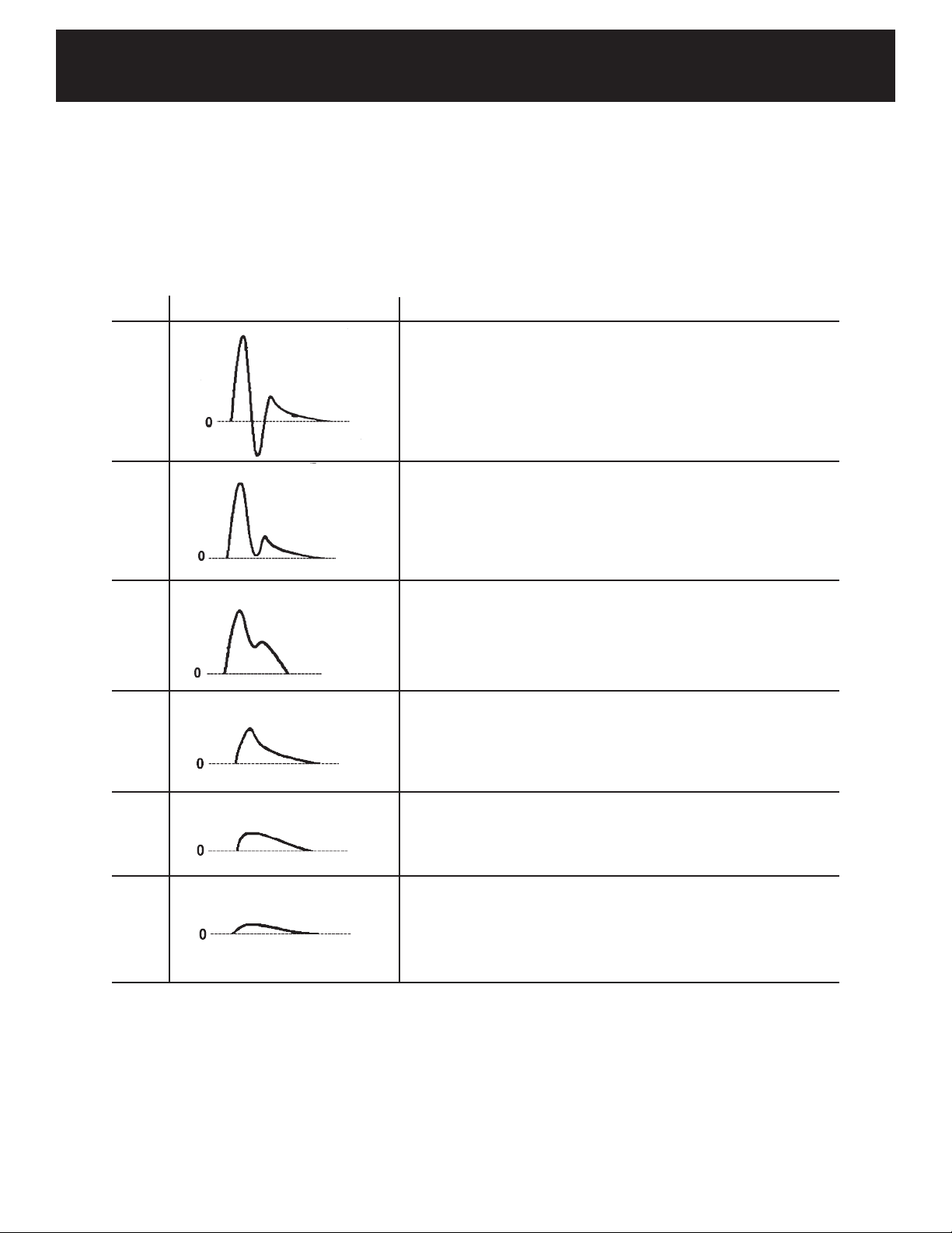
2. Lower Extremity Doppler Arterial Waveform Pattern Analysis ........................................3
3. Controls
3-1 Front Left View .............................................................................................................. 4-5
3-2 Front Right View & Probe ..................................................................................................6
4. Setup & Operation
4-1 Turning the Unit ON / OFF ................................................................................................7
4-2 Checking the Battery Level ...............................................................................................8
4-3 Charging the Battery .........................................................................................................9
4-4 Discharging the Battery .....................................................................................................9
4-5 Installing Printer Paper ....................................................................................................10
5. Basic Operation
5-1 Measuring Blood Velocity ...........................................................................................11-12
5-2 PPG: Arterial Pulse Waveform Studies ...........................................................................13
5-3 Measuring Fetal Heart Rate (FHR) .................................................................................14
5-4 Fetal Heart Rate (FHR) Monitoring .................................................................................15
5-5 Air Emboli Monitoring ......................................................................................................16
6. Mode & Menu Settings
6-1 Menu
6-1-1 Menu Structure .......................................................................................................17
6-1-2 Menu Operation ......................................................................................................18
6-1-3 Menu for Blood Velocity Measurement...................................................................19
6-1-4 Menu for Blood Velocity Freeze Mode ...................................................................20
6-1-5 Menu for PPG (Photoplethysmography)(Measurement & Freeze) ........................21
6-1-6 Menu for 2.25 MHz Fetal / Beep Mode ..................................................................22
6-2 Mode Setting Details
6-2-1 MEMORY - STORE ................................................................................................23
6-2-2 MEMORY - READ ..................................................................................................24
6-2-3 MEMORY - CLEAR ................................................................................................24
6-2-4 MODE (Baseline Mode) .........................................................................................25
6-2-5 DIR (Flow Direction) ...............................................................................................25
6-2-6 TIME (Time Scale) ..................................................................................................25
6-2-7 FLOW (Blood Volume Flow) / DIAMETER (Est. Vessel Diameter) ........................26
6-2-8 PATIENT (Patient Data Input) ........................................................................... 26-27
6-2-9 OTHERS - LANGUAGE .........................................................................................28
6-2-10 OTHERS - FREEZE .............................................................................................28
6-2-11 OTHERS - UNIT ...................................................................................................28
6-2-12 OTHERS - FILTER (Arterial / Venous Filter) ........................................................28
6-2-13 OTHERS - SMOOTH (Smoothing Filter) ..............................................................28
6-2-14 DISP / OTHERS - DISP (Waveform / Data) .........................................................29
6-2-15 OTHERS - CAL (Calibration) ................................................................................29
6-2-16 OTHERS - BACKLIGHT .......................................................................................29
6-2-17 OTHERS - AUTO OFF (Automatic Shut O) ........................................................30

TABLE OF CONTENTS
6-2-18 OTHERS - P.ID PRT (Patient Data Print) .............................................................30
6-2-19 OTHERS - PRB-KEY (Probe Button Function) ....................................................30
6-2-20 OTHERS - DATE (Date and Time Setting) ...........................................................30
6-2-21 OTHERS - PRB20MHZ (20 MHz Probe Selection) ..............................................31
Mode Settings for Optional PPG Probe
6-2-22 AC/DC (Arterial/Venous) .......................................................................................31
6-2-23 COUNT .................................................................................................................31
Mode Settings for Optional 2.25 MHz Probe
6-2-24 DISP (Display Mode) ............................................................................................31
6-2-25 SOUND (Beep Sound for FHR Mode) ..................................................................32
6-2-26 UPPER (Upper Limit for FHR) ..............................................................................32
6-2-27 LOWER (Lower Limit for FHR) .............................................................................32
6-2-28 DISP / BEEP (Display for Beep Mode) .................................................................32
6-2-29 LIMIT-1 (Limit for Beep Mode) ..............................................................................33
6-2-30 LIMIT-2 (Maximum/Average for Beep Mode) .......................................................33
6-2-31 OTHERS - UNIT (Beep mode Unit) ......................................................................33
7. LCD Display
7-1 Blood Velocity
7-1-1 Waveforms .............................................................................................................34
7-1-2 Numerical Data .......................................................................................................35
7-2 Fetal Heart Rate Mode
7-2-1 Displaying Real Time FHR (Data Mode) ................................................................35
7-2-2 Monitoring FHR in Graph (Wave Mode) .................................................................36
8. Printing Waveforms & Data
8-1 Mode Settings Inuencing the Printed Chart ...................................................................37
8-2 How to Print ............................................................................................................... 37-38
8-3 Print Sample ....................................................................................................................38
9. Numerical Data ...................................................................................................................39
10. External Outputs
10-1 Headset .........................................................................................................................40
10-2 Communication Port ......................................................................................................40
11. Maintenance ........................................................................................................................41
12. Symbol List .........................................................................................................................41
13. Operating Principles .........................................................................................................42
14. Block Diagram ...................................................................................................................43
15.Specications .....................................................................................................................44
16. Operation Storage & Transport Environments .................................................................45
17. System Includes .................................................................................................................45
18. Cleaning ..............................................................................................................................46
19. Disposal of Device ..............................................................................................................47
20. Warranty ..............................................................................................................................47
21. Safety Standards ........................................................................................................... 48-50
SECTION 2 (Vascular Testing Instructions)
1. Ankle Brachial Index .................................................................................................... 51-52
2. Segmental Blood Pressures ....................................................................................... 53-54
3. Venous Compression Studies ..................................................................................... 55-56
4. PPG Toe Pressures & Toe Brachial Index (TBI) ......................................................... 57-58
5. PPGVenousReux ...................................................................................................... 59-60

Section1
Section1
Basic Operation

Smartdop®45BasicOperation
Thank you for choosing the
Smartdop®45…
e Smartdop® 45 is a bidirectional Doppler with LCD display and integrated printer
used for the detection of arterial and venous blood ow in extremities and fetal heart
sounds. Please read this manual carefully to acquaint yourself with the proper
operation.
1
Smartdop and Smart-V-Link are registered trademarks ® of Koven Technology, Inc.
FEATURES
• Bidirectional hand held Doppler with LCD and integrated printer
Displays real-time waveforms, numerical data and heart rate
Prints frozen waveforms, numerical data, monitored heart rate and patient data
• Microprocessor based
Various mode settings available for optimal measurement with the LCD menu and unique scroll button
30 waveform memory storage for waveform, numerical data, heart rate, and patient data
• Convenient probe activation button
Freezes and/or prints waveform and numerical data for documentation purposes
• AutomaticPower“o”
• USB computer interface
Optional communication cable and Smart-V-Link®software are available
Store waveforms and numerical data to a computer for data analysis and electronic storage
• Optional PPG (Photoplethysmography) probe available for expanded arterial and
venous testing
NOTE
If using the Smartdop®45 with the optional Smart-V-Link®documentation software, please
refer to the Smart-V-Link®operation manual for instructions on downloading waveforms and
performing tests with the Doppler and software.
Manufactured by:
Hadeco, Inc.
2-7-11 Arima, Miyamae-ku, Kawasaki, 216-0003 Japan
CAUTION
Use the Smartdop®45 under normal operating conditions, according to the instructions
provided in this operation manual and under the operating conditions stated in the product
specications.
CAUTION
Federal law restricts this device to sale by or on the order of a licensed healthcare practitioner.
RX only.
CAUTION
The Smartdop®45 has not been evaluated for safety and compatibility in the MR environment.
The Smartdop®45 has not been tested for heating or migration in the MR environment.
CAUTION
Perform ultrasound testing/procedures prudently using the principle of ALARA (As Low As
Reasonably Achievable).

Smartdop®45BasicOperation
1. INDICATIONS FOR USE, CONTRAINDICATIONS, &
APPLICATIONS
INDICATIONS FOR USE
The Smartdop® 45 is used for the detection of arterial and venous blood ow in extremities as
well as fetal heart sounds. It displays and prints bidirectional velocity waveform, numerical data
and fetal heart rate with heart beat indicator.
CONTRAINDICATIONS
None known.
APPLICATIONS
(Refer to section 2 for Noninvasive Arterial & Venous testing instructions)
1-1 DOPPLER ARTERIAL & VENOUS APPLICATIONS
• Ankle Brachial Index (ABI) studies • Systolic pressures
• Peripheral vascular procedures • Blood ow velocity
• Segmental studies • Penile & digit systolic pressures
• Venous compressions
1-2 PPG (PHOTOPLETHYSMOGRAPHY) ARTERIAL & VENOUS APPLICATIONS
(Requires optional PG-21 Photoplethysmography probe, supplied separately)
• PPG toe pressures & Toe Brachial Index (TBI)
• PPG venous reux
1-3 FETAL APPLICATIONS
(Requires optional fetal probe, supplied separately)
• Evaluation of fetal heart rate and sounds throughout pregnancy except during rst
trimester, where fetal heart is not suciently developed.
1-4 AIR EMBOLI MONITORING
(Requires optional BF2M20S8A at monitoring probe, supplied separately)
• Monitoring for the detection of venous air embolism
2

Smartdop®45BasicOperation
2. LOWER EXTREMITY DOPPLER ARTERIAL
WAVEFORM PATTERN ANALYSIS
The Doppler arterial waveforms obtained from the lower extremity may be classied into six
categories as an aid in interpretation.
TYPE TYPICAL WAVEFORM FINDINGS
0 The contour exhibits a steeply rising upslope at the onset of systole,
rapid systolic downslope, and reverse ow (below baseline). Dop-
pler sounds are loud and sharp. Normal peak forward velocity = 30
+/- 10 cm at the dorsalis pedis artery.
I The contour demonstrates a strong but diminished systolic compo-
nent and loss of reverse ow. The width of systolic pulse is broad-
ened. The Doppler sounds are diminished very little as compared
to the type “O” pattern.
II The contour shows prolongation of both the upstroke and the down-
stroke and diminished waveform amplitude (attening). Doppler
sounds are heard during systole and continuing through all or most
of diastole.
III The contour exhibits slowly rising velocity during systole, and the
amplitude of the waveform is reduced. Doppler sounds are not
sharp even during systole.
IV The amplitude of the waveform and the Doppler sounds is greatly
reduced.
V The amplitude of the waveform is extremely reduced. The contour
is hardly recognizable as an arterial blood ow waveform. The
Doppler sounds are very faint.
3

Smartdop®45BasicOperation
5. CONTROLS
5-1 FRONT LEFT VIEW
1) PAPER COVER Place paper inside
2) COVER OPEN BUTTON To open the paper cover.
3) LCD DISPLAY Displays waveform, numerical data,
heart rate, and menu for mode settings.
4) SPEAKER Outputs Doppler sounds.
5) PROBE CONNECTOR 1 To connect the probe.
6) POWER BUTTON To turn the unit ON / OFF.
7) VOLUME CONTROL To adjust sound volume.
8) STRAP HOLE To attach hand strap.
9) HEADSET To connect a headset (not provided).
Cuts o sound to the speaker.
10) AC ADAPTOR CONNECTOR To connect the designated AC adaptor.
Scroll Button
4
3. CONTROLS
3-1 FRONT LEFT VIEW

Smartdop®45BasicOperation
3. CONTROLS
3-1 FRONT LEFT VIEW (Cont.)
11) PROBE CONNECTOR 2 To connect a second probe (press the probe
button to select)
12)CHARGING INDICATOR Indicates battery charging status.
Orange: Charging
Green: Fully charged
13)SCROLL BUTTON Consists of 5 internal buttons having the
following functions:
14)UP To scroll up through menu items
To increase waveform memory number in
Freeze mode
To move cursor up on the on-screen
keyboard
15)RIGHT To move cursor right on the on-screen
keyboard
To go to the sub-menu
16)DOWN To scroll down through menu items
To decrease waveform memory number in
Freeze mode
To move cursor down on the on-screen
keyboard
17)LEFT To move cursor left on the on-screen
keyboard
To return to the main menu from the sub-
menu or exit from the menu
18)ENTER To go to the menu
To perform the selected command on the
menu
19)PRINT / BACK BUTTON To activate / deactivate the printer.
To return to the previous screen
To exit Site Guidance mode (For use with
Smart-V-Link®Vascular software only. See
the Smart-V-Link®Operation Manual for
details)
5

Smartdop®45BasicOperation
3. CONTROLS
3-2 FRONT RIGHT VIEW AND PROBE
1) PROBE HOLDER For probe placement when not in use.
2) COMMUNICATION PORT To connect the Doppler to a computer
3) PROBE To connect the probe
4) PROBE BUTTON To freeze the waveform & numerical data.
To activate and deactivate the printer.
Note: The function of the probe button
is dened in the menu PRB-KEY. See
6-2-19 “OTHERS-PRB-KEY (Probe
Button Function)” for details.
5) PROBE CAP To protect the probe transducer tip when
not in use.
6

Smartdop®45BasicOperation
4. SETUP & OPERATION
4-1 TURNING THE UNIT ON / OFF
1. Connect the probe with the alignment mark on
the probe connector pointed up (12 o’clock).
2. Press the power button to turn the unit ON.
The Doppler will briey display the type of
probe connected.
If no probe is connected, the Doppler will
display “NC” on the display indicating that there
is “no connection”
3. When the battery is low, a low battery indicator
appears, as shown on the right. Although the
Smartdop®will continue to work for awhile, we
strongly recommend recharging the battery as
soon as possible before further use.
See 4-3 “Charging the Battery” for details
4. AUTOMATIC POWER OFF
When the unit is in AUTO-OFF mode, the power will automatically shut o after
the following time passes:
(a) 35 minutes when in measurement. (Fetal Heart Rate WAVE mode only)
(b) 15 minutes when in measurement (Except Fetal Heart Rate WAVE mode)
(c) 10 minutes when in freeze mode
(d) 5 minutes when no signal is present
Power button
Alignment mark
Low battery indicator
7

Smartdop®45BasicOperation
4. SETUP & OPERATION
4-2 CHECKING THE BATTERY LEVEL
The battery level indicator is shown in the upper right
corner of the menu screen.
1. Turn the unit on and press the Enter button to
display the MENU screen.
2. The battery level indicator shows the battery
level in 4 stages, as shown in the illustration on
the right.
3. Charge the battery when the indicator shows
that the battery level is low.
See 4-3 “Charging the Battery” for details
High
Medium
Low
Empty
8

Smartdop®45BasicOperation
4. SETUP & OPERATION
4-3 CHARGING THE BATTERY
Charge the battery fully before using the Smartdop®
45 for the rst time.
1. Turn the unit o and plug in the AC adaptor.
2. The charging indicator light will turn solid
orange to indicate that charging is in process.
When the battery is fully charged, the charging
indicator light will turn solid green. Unplug the
AC adaptor from the Doppler before performing
any tests.
4-4 DISCHARGING THE BATTERY
Periodically discharging the battery completely may
help prolong battery life.
1. To discharge the battery, turn the Doppler o
and plug in the AC adaptor.
2. Hold down the back button and press the Right
button at the same time. “DISCHARGE” will be
displayed on the LCD.
3. After discharging is complete the charge
process will start automatically, “DISCHARGE”
will no longer be shown on the LCD and the
charging indicator light will turn solid orange.
Charging indicator
AC adaptor connector
Back button
Right button
9
NOTE
Use only the designated adaptor that came with your
Smartdop®45 or contact Koven Technology for parts
& accessories.
NOTE
It takes approximately 3 hours to fully charge the
battery.
NOTE
Battery life is approximately 300 full charges.
When charge life becomes obviously short,
contact Koven for battery replacement.

Smartdop®45BasicOperation
4. SETUP & OPERATION
4-5 INSTALLING PRINTER PAPER
1. Press the Cover Open button on the top of the
unit to open the paper cover and remove the
paper roll shaft.
2. Insert the roll shaft into the new paper roll.
3. Place the shaft and paper roll in the paper
compartment as shown in the illustration on the
right. Pull the paper edge out a few inches and
close the paper cover.
Cover Open button
10

Smartdop®45BasicOperation
5. BASIC OPERATION
5-1 MEASURING BLOOD VELOCITY
This section explains the fundamentals of using
the Smartdop® 45 to measure blood velocity.
For detailed instructions on performing
specic tests, please refer to Section 2
Testing Instructions.
1. Connect the probe to probe connector 1. The
alignment mark on the probe connector should
be pointed up (12 o’clock position).
2. Press the power button to turn the unit on.
Turn the volume control to the desired level.
3. Place ultrasonic gel on the probe tip or the
patients skin. Make sure there is enough gel to
cover the tip of the probe.
If you would like to enter patient data, see 6-2-
8 “PATIENT (Patient Data Input)” for details.
4. Place the probe on the measurement area at
an angle of approximately 45° to 60° against
ow, and locate the point where maximum
Doppler sounds are heard.
Alignment mark
Volume control
Power button
11
CAUTION
The probe transducer tip is thin and delicate.
Please handle with care and use the probe cap
when not in use.
CAUTION
Use ultrasound gel. Other materials such as baby
oil or cream may produce incorrect sounds or
damage the probe.
WARNING
The ultrasound gel included with purchase is non-
sterile and should only be used noninvasively.
WARNING
Discontinue use of ultrasound gel if an allergic
reaction occurs.

Smartdop®45BasicOperation
5. BASIC OPERATION
5-1 MEASURING BLOOD VELOCITY (cont.)
5. When the waveform becomes rhythmic and
stable, wait 5 seconds or more without moving
the probe. Then, press the probe button to freeze
and/or print the waveform.
6. If you would like to save the data in memory, see
6-2-1 “MEMORY - STORE” for details.
WARNING
If any abnormality is found on
the unit or patient, discontinue
use in a manner safe to the
patient.
12
NOTE
The probe button function can be set to
PRT&FRZ, PRINT only, or FREEZE only. See 6-2-
19 “OTHERS - PRB-KEY (Probe Button Function)”
for details. If FREEZE only is selected, the
waveform can be printed by pressing the Print
button.
NOTE
If FREEZE mode is set for AUTO, the Smartdop
will freeze the waveform automatically once the
waveform becomes stable. See 6-2-10 OTHERS -
FREEZE for details.

Smartdop®45BasicOperation
5. BASIC OPERATION
5-2 PPG: ARTERIAL PULSE WAVEFORM STUDIES
(Requires the optional PPG probe (PG-21), supplied separately.
This section explains the fundamentals of performing a PPG arterial study using the
Smartdop 45 with the optional PG-21 Photoplethysmography (PPG) probe. For detailed
instructions on performing PPG toe pressures and calculating the Toe Brachial
Index (TBI) ratio, please refer to Section 2 Testing Instructions.
1. Connect the PPG probe to probe connector 1. The
alignment mark on the probe connector should be
pointed up (12 o’clock position). Turn the Doppler
on.
2. Press the Enter button to display the MENU and
make sure the MODE is set on AC mode. If
necessary, switch to AC mode by pressing Enter
while MODE is highlighted. Press the left button to
exit the menu.
3. Ax the PPG sensor with the clear side against the
skin surface using a Velcro strap or double-sided
clear tape.
4. To input patient information, see 6-2-8 “PATIENT
(Patient Data Input)” for details.
5. The Smartdop®45 automatically adjusts the gain
and the PPG waveform is shown on the LCD.
6. When the waveform becomes stable and rhythmic,
press the Right button or probe button to freeze
and/or print the waveform.
7. If you would like to save the data in memory, see
6-2-1 “MEMORY - STORE” for details.
Power button
Alignment mark
Enter button
13
NOTE
The probe button function can be set to PRT&FRZ, PRINT
only, or FREEZE only. See 6-2-19 “OTHERS - PRB-KEY
(Probe Button Function)” for details. If FREEZE only is
selected, the waveform can be printed by pressing the
Print button.
WARNING
If any abnormality is found on the unit or patient,
discontinue use in a manner safe to the patient.

Smartdop®45BasicOperation
5. BASIC OPERATION
5-3 MEASURING FETAL HEART RATE (FHR) (2.25 MHz probe, DATA mode)
(Required optional fetal probe, supplied separately)
This section explains the fundamentals of using the
Smartdop®45 with a fetal probe to measure fetal
heart rate.
1. Connect the 2.25 MHz probe to the Smartdop® 45
with the alignment mark on the probe connector
pointed up (12 o’clock position).
2. Turn the Doppler ON and adjust the volume to the
desired level.
3. Press the “Enter” button to display the MENU.
Scroll to DISP, press Enter and scroll to DATA.
Press Enter to set.
4. Place ultrasonic gel on the top of the probe or the
patient’s skin. Use enough gel to cover the top of
the probe.
If you would like to enter patient data, see 6-2-8
“PATIENT (Patient Data Input)” for details.
5. Place the probe on the middle of the abdomen at a
right angle (90°) to the skin surface, and move slowly
to locate maximum Doppler heart beat sounds. The
probe needs to just lightly touch the skin.
6. When the heart rate becomes stable, press the
Probe button or Right button to Freeze.
Power button
Alignment mark
Volume control
14
NOTE
Be sure to verify the fetal heart rate. (Maternal
heart rate matches the maternal pulse rate).
Enter button
WARNING
If any abnormality is found on the
unit or patient, discontinue use in
a manner safe to the patient.
CAUTION
Use ultrasound gel. Other materials such as
baby oil or cream may produce incorrect sounds
or damage the probe.
WARNING
The ultrasound gel included with purchase is non-
sterile and should only be used noninvasively.
WARNING
Discontinue use of ultrasound gel if an allergic
reaction occurs.

Smartdop®45BasicOperation
5. BASIC OPERATION
5-4 FETAL HEART RATE (FHR) MONITORING (2.25 MHz Monitoring Probe, WAVE mode)
(Required optional 2.25 MHz at monitoring probe, supplied separately)
This section explains the fundamentals of using the Smartdop® 45 with a fetal monitoring probe
to monitor fetal heart rate over a period of time.
1. Connect the 2.25 MHz fetal monitoring probe (Model
BF2M20S8C) to the Smartdop® 45 with the alignment
mark on the probe connector pointed up (12 o’clock
position).
2. Turn the Doppler ON and adjust the volume to the
desired level.
3. Press the “Enter” button to display the MENU. Scroll to
DISP, press Enter and scroll to WAVE. Press Enter to set.
Choose upper and lower limits if required. See 6-2-26
UPPER and 6-2-27 LOWER for details. Press the
Left button to exit the menu.
4. Place gel on the patient’s skin. Use enough gel to
cover the top of the probe.
If you would like to enter patient data, see 6-2-8
“PATIENT (Patient Data Input)” for details.
5. Place the probe in the middle of the abdomen at
against the skin surface and move slowly to locate
maximum Doppler heart beat sounds. Hold the probe
in place or use a strap to attach the probe to the
abdomen during monitoring.
6. The LCD will show the monitoring waveform and
numerical heart rate. Press the probe button or Right
button to freeze the waveform. Up to 33 minutes of
FHR monitoring can be displayed over 4 LCD screens
(approx. 8 minutes per screen). If you would like
to save the data in memory, see 6-2-1 “MEMORY -
STORE” for details.
NOTE
If FHR exceeds the upper and/or lower limits, the LCD will begin to ash and a beep
sound will be heard if SOUND is set ON in the MENU. See 6-2-25 SOUND for details.
NOTE
Be sure to verify the fetal heart
rate. (Maternal heart rate matches
the maternal pulse rate)
15
Power button
Alignment mark
Volume control
Enter button
WARNING
If any abnormality is found on the
unit or patient, discontinue use in a
manner safe to the patient.
CAUTION
Use ultrasound gel. Other materials such as baby
oil or cream may produce incorrect sounds or
damage the probe.
WARNING
The ultrasound gel included with purchase is non-
sterile and should only be used noninvasively.
WARNING
Discontinue use of ultrasound gel if an allergic
reaction occurs.
Table of contents
Other Koven Medical Equipment manuals
Popular Medical Equipment manuals by other brands

Juzo
Juzo Thorax Instructions for use

K.H. DEWERT
K.H. DEWERT 2800XL Series user manual

Savaria
Savaria Track Bridge M92940 Series owner's manual

Graham Field
Graham Field LUMEN Ortho-Biotic II FR597G Series manual

Otto Bock
Otto Bock 50R236 Smartspine SI Instructions for use

GE
GE Marquette 418793-001 Service manual