Kowa KGC-01 User manual

Writing:May , 2020
KOWA LUBRICATING SYSTEMS
GREASE CHECKER
MODEL : KGC-01 / KGC-02
INSTRUCTION MANUAL
KOWA CORPORATION

Introduction
Thank you very much for purchasing the KOWA LUBRICATING SYSTEM.
This Instruction Manual has been compiled as a practical guide for the operation and
maintenance of the Grease Checker.
All descriptions contained herein are based on the standard system, which may, therefore, be
different from those of the purchased system. Such a problem can be solved by referring to the
final specifications. However, it is required to understand that some changes caused by the
modification of equipment may not be described in the final specifications.
Warranty
The warranty period for this system will be one year from the commencement of operation.
Any defect or failure occurring during the warranty period, for which KWK is liable in design and
manufacturing, shall be corrected and / or eliminated by KWK without compensation.
However, any defect or failure caused by improper operation which is not described in this
Instruction Manual shall not be guaranteed, even though the defect or failure occurs witch the
guaranteed period.
Contact
If you have any suspicions or questions in this instruction manual, please contact our distributor
which supplied this device.
Parts order
Please order from our distributor that provided this device.

PRECAUTIONS OF SAFETY
○Before the installation, operation, maintenance and inspection, read carefully this
instruction manual and other accompanying documents for correct service.
Familiarize with the knowledge of equipment, information of safety and all of cautionary
instructions for service.
The precautions of safety are shown in each equipment of the centralized lubricating
system by using safety mark.
Particular attention should be called to the places where these safety marks are given.
The safety marks are classified into "WARNING" and "CAUTION", but there are other
equivalent displays.
Please be sure to follow as they contain important contents.
If mishandled; a dangerous situation may
occur, it could result in death or serious
injury.
If mishandled; a middle injury or light injury
and a physical damage may occur.
For the matter being mentioned in the CAUTION, it may result in an importance
according to situation. The important content is given to all of safety mark, and obey it
without fail.
The Maximum Working Pressure of this equipment is 3MPa (30kg/cm2).
In case to disassemble and inspect each equipment, stop the operation of pump, and
release the pressure to decrease the operation as 0MPa (0kg/cm2).
If the pressure is increased under the condition in which air is in the pipe, the air in the
pipe is compressed.
When releasing the pressure or removing the piping, if you face or your body face in the
direction which the air will escape, the grease in the piping may blow out, which is
dangerous. Do not point your face or body in the direction which the air blows out as it may
cause an accident or injury.

Precautions for use
1. Precautions for mounting and piping
A. When installing, make sure no foreign matter such as dust gets into the equipment and piping.
It may cause malfunction or failure.
In addition, do not drop it, as dropping it may distort or damage internal parts and cause
malfunction.
B. Grease filling and grease flushing
Be careful when constructing, as dust and air can cause malfunction.
a) Piping behind distribution valve (from the distribution valve to the grease point)
Fill the piping from the distribution valve to the bearing (greasing point) with grease before
installing the piping.
When filling the grease, be careful not to let dust or air enter the piping.
b) Piping from pump to distribution valve
The piping between the pump and the distribution valve should be filled with grease after the
piping is installed.
Please be careful not to put dust or air in the same way as well as “a)”.
c) At the time of filling, pay attention to the remaining amount of grease in the tank, pail, drum,
etc., which is the supply source, and do not enter air.
d) After filling, run the grease for a while and check the condition of dust, air, etc., and make
sure that the grease is clean.
Please note that dust and grit that has entered the piping will not come out immediately.
2. Before the test run
Confirm that the piping installation and grease flushing are completed.
Check for loose fittings of the piping.
3. Other
Please read the instruction manual carefully and use the product correctly.

1
Table of Contents
1. Overview···································································· 2
2. Composition································································ 2
3. Specification ······························································· 2
4. Usage ········································································ 3
5. Maintenance and inspection·········································· 4
6. Operating method and precautions for use ······················ 4
7. Precautions for installation ··········································· 5
8. Troubleshooting··························································· 6

2
1. Overview
The grease checker is a product that allows you to visually confirm that grease lubrication
(centralized lubrication) is being performed accurately. It is a product that can visually confirm
lubrication failure due to damage to the lubrication pipes and hoses and prevent seizure of
bearings.
2. Composition
The grease checker consists of the main body, an indicator for detecting grease supply, and a
grease nipple. The grease checker is installed behind the distribution valve for centralized
lubrication, and is used directly on the bearing or by connecting to the pipe near the bearing.
When grease is sent to the grease checker, the attached indicator will perform a stroke
operation and you can confirm that the grease has been sent.
3. Specification
Model
KGC-01
KGC-02
Operating Oil Content
About 0.5 ㎤
Indicator Working Pressure
About 0.2-0.3MPa
Cracking Pressure
(Built-in Check Valve)
About 0.4MPa
Max Working Pressure
Max. 3MPa
Consistency
Grease NLGI No. 1 or less
Temperature
0℃~80℃
0℃~135℃
IP Standard
Equivalent to IP44
Weight
0.5 kg
※The heat resistant temperature excludes grease deterioration.
If the grease does not flow due to heating for a long time, the grease may solidify and an
abnormality may occur inside the grease checker, reducing the cracking pressure and the indicator
may not operate.

3
4. Usage
①Connect the discharge port side of the grease checker body directly to the bearing or to a pipe,
and connect the supply port side to the distribution valve outlet side pipe. (Figure 1)
※At this time, be careful not to let dust get inside the grease checker or piping.
②When the grease sent by pressure from the pump is sent to the grease checker through the
distribution valve, the indicator attached to the grease checker strokes up to confirm the
grease can be made sure to being sent. (Figure 2)
③After the indicator attached to the grease checker is activated, manually push down the
push-in button to reset it when checking the equipment. (Figure. 3)
※Pushing down the push-in button to the end, the built-in check valve is pushed down to
reduce the reverse flow of grease in the indicator stroke part, and releasing the internal
pressure to the bearing side, to prevent the indicator returns by back pressure.
④The cracking pressure of the built-in check valve in grease checker can be adjusted. Looking
at the adjustment nut from the discharge side of the main unit, turning it to the right increases
the cracking pressure, and turning it counter-clockwise decreases the cracking pressure.
(Figure. 5)
⑤It is also possible to supply grease with a manual grease gun or an electric grease gun from
the grease nipple mounted to the grease checker. (Figure. 4)
※When using a manual or electric grease gun, pay attention to the discharge pressure and
do not exceed the grease checker operating pressure of Max.3MPa.
※Figures are KGC-01
Figure. 1 Figure. 2 Figure. 3
Figure. 4 Figure. 5

4
5. Maintenance and inspection
No special maintenance or inspection is required, but be careful not to let dust in the grease.
Also, check and clean it so that dust and sand do not adhere to the indicator mounted to the
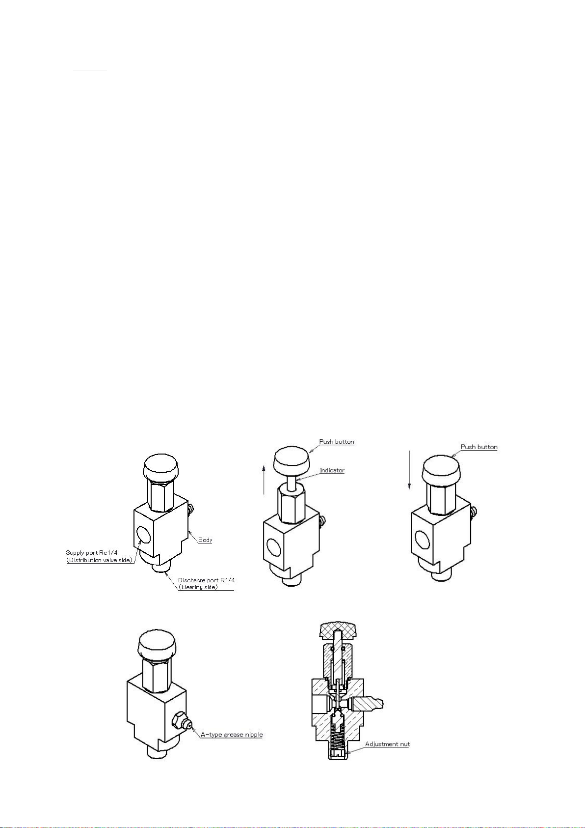
grease checker and the grease nipple. When lubricating from the grease nipple, wipe the grease
nipple and the tip of the grease gun nozzle cleanly before connecting the nozzle to lubricate.
In addition, grease for lubrication is applied to the indicator, and the grease inside is adhered
thinly. It is within the normal specification range that grease is attached to the indicator.
Due to the structure of the indicator, which keeps the internal seal lubricated and operates
smoothly, internal-grease and oil may adhere to the indicator during use (when the indicator
reciprocates). If internal-grease and oil are accumulated on the top of the main unit while
repeating the operation of the indicator, clean it regularly.
6. Operating method and precautions for use
①If the back pressure from the bearings behind the grease checker is high, it may be pushed
back by the back pressure when the indicator attached to the grease checker is reset. Please
reset after a while, or push down the indicator all the way to release the grease inside.
②If there is a pipe after the grease checker, the pressure loss of the grease will occur
depending on the length and diameter of the pipe. If the pressure loss of the grease pipe is large,
reset it after a while, or push down the indicator to the end to release the grease inside, as in the
case of ①.
③If the indicator is pushed back even after performing (1) or (2), mount a check valve to the
grease checker supply port. By installing a check valve, you can reduce the phenomenon of
pushing back when the indicator attached to the grease checker is reset.
④It is also possible to detect a high pressure condition by installing a check valve at the grease
checker supply port. By the check valve, when the indicator attached to the grease checker is
pushed in, the pushed-in grease will flow to the bearing side. In case it is normal, pushing the
indicator will keep it in that state, but if the bearing is under high pressure due to back
pressure, etc., the indicator will not be pushed in or will be pushed back immediately. In this
state, the back pressure on the bearing side is high, and it can be judged that it is a high
pressure state.
⑥While the grease checker is in use (when the indicator reciprocates), internal grease and oil
will adhere to the indicator, but this is due to the structure in order to maintain the lubricity of
the seal part and to operate smoothly. This is within the normal specification range that grease
is attached to the indicator. (5. Also described in maintenance and inspection)
⑥If the grease checker is not used for a long time, the sliding surface of the indicator attached
to the grease checker and the sliding O-ring may lose lubrication and stick to it. In that case,
turn the indicator push-in button to remove it.

5
7. Notes on installation
The grease checker has a structure in which the indicator is manually pushed back after it
operates. Install the grease checker within the reach of people.
Do not install the grease checker with the indicator attached to the grease checker facing
downward. The indicator may operate due to equipment vibration.
When mounting, be careful not to overtighten when screwing in the outlet side.
Image is for illustration purposes.

6
8. Troubleshooting
Conditions
Possible Causes
How to deal with
Indicator pushed back on
reset
High back pressure and
high pressure loss
behind grease checker
Reset again after a while
Push down the indicator all the way
to release the grease inside.
Turn the adjusting nut
counterclockwise as seen from the
discharge side to reduce the cracking
pressure.
Install a check valve at the grease
checker supply port
Indicator not working
The indicator sliding
surface is stuck due to
unused for a long time
Turn the indicator push button left
and right several times
The indicator operating
pressure is higher than
the specified value due
to long-term unused.
Increase the cracking pressure by
turning the adjustment nut
clockwise as seen from the discharge
port side.
Grease leaks from the
sliding part of the indicator
(In the case of a leak of the
same amount as the
distribution valve discharge
amount)
Inner O-ring wear
O-ring replacement
※If the problem is still not solved after performing the above,
please contact your distributor or sales office.
This manual suits for next models
1
Table of contents
Other Kowa Laboratory Equipment manuals
Popular Laboratory Equipment manuals by other brands

Keit
Keit IRmadillo ASM0627-09-Z-C-O-G-D2 Series user manual

Amos
Amos AEM 480 Operation manual

Thermo
Thermo 8600 Series Operating and maintenance manual

San Telequip
San Telequip SPS PSE 1310 Series quick start guide

Showa Denko
Showa Denko Shodex Shodex IC SI-36 4D Operation manual

Swiss Peak
Swiss Peak P762.551 quick start guide

Thermo Scientific
Thermo Scientific TriPlus RSH Preinstallation manual

SUSS
SUSS MJB4 Safety and installation

Neuation
Neuation iFUGE M24PR Product user manual

Agilent Technologies
Agilent Technologies 8000 Series Operator's manual

Fluke
Fluke RSE300 user manual

Thermo Scientific
Thermo Scientific CRYO Plus 1 Operating and maintenance manual