INTRODUCTION
INTRODUCTION
P0-7
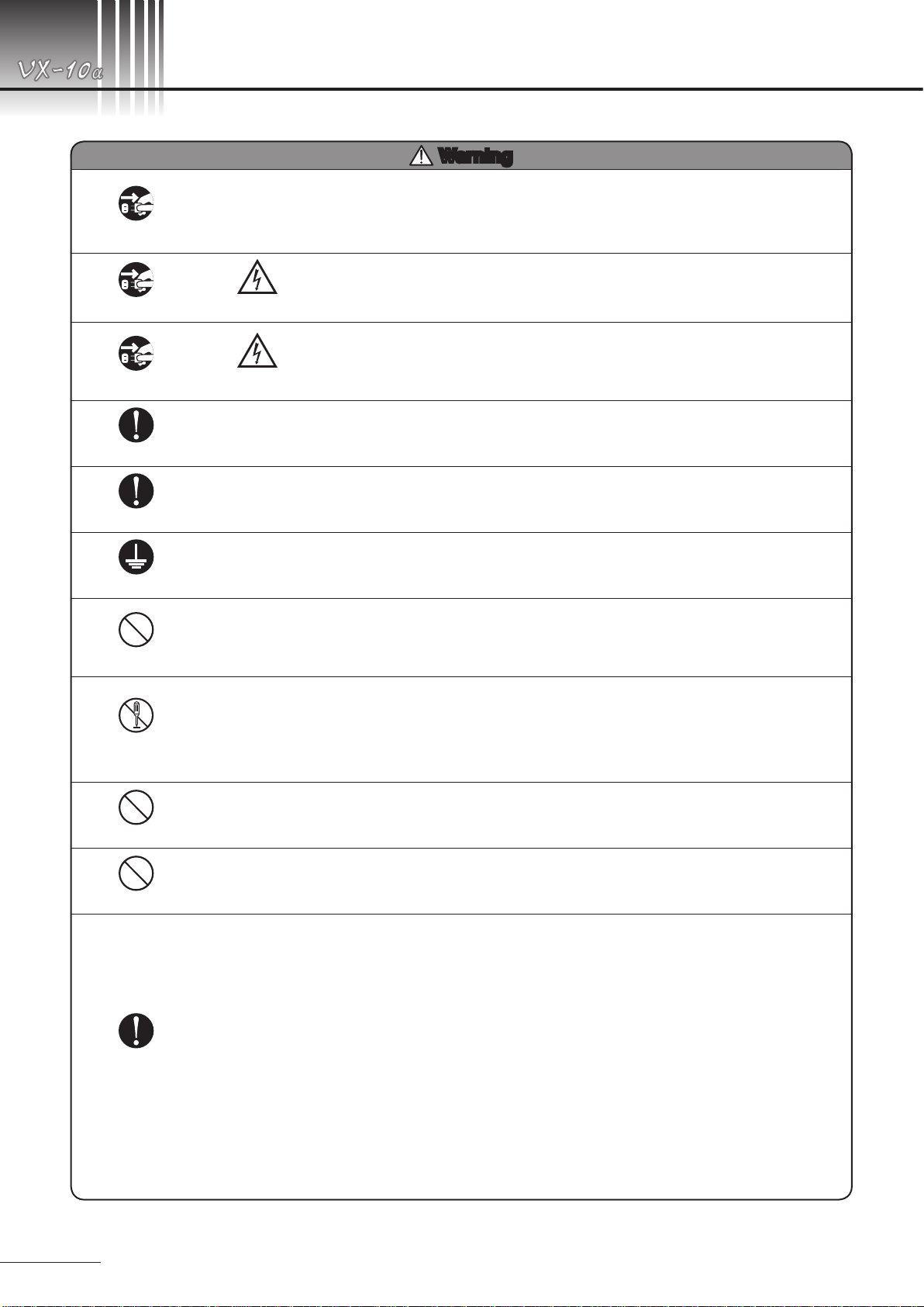
Precautions in operation
● Do not turn ON/OFF the main switch in succession.
There should be an interval of 5 seconds or more.
● When plugging or unplugging, turn OFF the main
switch beforehand.
● Do not change the camera back with the main switch
ON.
●The power line from the power outlet must be exclu-
sively connected to the fundus camera.
Precautions on the main camera unit and
relative systems
● If any stain, smear or scratch should exist on objective
lens, it will appear as a white spot on pictures taken.
Therefore, it is essential to always keep the lens sur-
face clean.
●Do not leave the camera mount open without camera
back mounted. In case the camera is expected to be
not used for a long period of time, be sure to seal the
mount with the accessory cap.
● Protect the optical viewnder barrel and eyepiece tube
from strong shocks or forceful pressures.
● Set a dial or knob with click(s) to its proper click index.
● If picture angle selector, lters in the observation light
system or dioptric lens for compensating the examined
eye should be incorrectly set, pictures taken will result
in failures such as vignetting, under-exposure, and so
forth.
● Securely x the camera back on the camera mount by
its lever. If not, pictures taken will result in failures such
as displaced or out-of-focus images. At worst, the cam-
era back may drop off and damaged and as a result,
you will be obliged to suspend photography.
● Because the main camera unit and camera back are
composed of precision parts, special tools will be
needed for adjustment. Do not attempt to disassemble
or adjust them by yourself.
Disposal Precautions
●LCD display of this instrument has a fluorescent
lamp that contains mercury. When disposing this
instrument, applicable federal, state, and local
regulations must be observed.
● When disposing, this instrument is categorized
as industrial waste; therefore, the disposal must
be handled by licensed industrial waste disposal
contractor.
● Only qualified personnel should operate this equip-
ment.
● When handling the fundus camera, pay special
attention not to give strong shock to it.
●Install and store the instrument in a place free from
high temperature and humidity, direct sunlight, and
avoid the dusty place. Strictly observe the following en-
vironmental conditions:
In operation
In Transportation, storage
Environmental Temperature
10 to 35°C -15 to +55°C
Relative Humidity
30 to 90% 10 to 95%
● When in use, in storage or in transit, care must be used
to keep the instrument from dewing.
● Place this fundus camera in room, the luminance of
which can be lowered as low as about 5 lx (the lumi-
nance as low as you can scarcely read newspaper).
● To keep the instrument dust-free, use the cover sup-
plied with it when the camera is not in use.
Precautions on electric system
●In case the KOWA should be used after a
long ‘unused’ period of time, inspect and check the fol-
lowing before starting it:
• The objective lens is neither dusty nor stained.
• The observation light's intensity has not changed.
• The battery (for instance, camera battery) the level of
which stays within service range.
●Connect the camera with the power outlet properly so
that the plug might not be pulled out accidentally.
But if it should occur, be sure to turn OFF the main
switch before connecting the plug again.
●If irregularity should occur in the circuit in the power
unit, for instance, when you plug in with the main
switch ON, “Err 1” will appear on the display and pho-
tographing will be disabled. In this case, turn OFF the
main switch and wait for a while. Then turn it ON. If
“Err 1”does not appear on the display, you may resume
photography.
● Kowa is not responsible for any failure(s) or damage(s)
caused by improvement, repair or maintenance ren-
dered by the third party other than Kowa and its autho-
rized agent.
● Kowa is not responsible for any failure(s) or damage(s)
caused by improvement, repair, or maintenance
rendered using the part(s) other than its designated
one(s).
● The line voltage should be within ±10% of the rated
value.
● Never change the electronic flash intensity when it’s
ashing is on.
● To operate switches on the control panel, rst turn ON
the main switch and then wait for about 10 seconds
(until the power unit becomes internally stable).