Kowa VX-10a User manual

KOWA
INSTRUCTION MANUAL
FUNDUS CAMERA
KOWA VX-10α
EU


IntroductionIntroduction
Introduction
P0-1
Introduction
This manual provides a description of the operating procedures of KOWA along with important
precautions to be observed during its use. Please read this entire manual carefully to assure that the instrument
can demonstrate its full capabilities and work safely. After you have finished reading, please keep this manual in an
easily accessible location near the instrument for future reference.
Operational considerations for safety
This manual describes important precautions to be observed during its use to assure that the instrument can be
used safely without causing any damage to the human body or property of its purchaser and other persons. The
designations and their pictorial symbols used in this manual have the following meanings. These should be fully
comprehended before reading the text of this manual.
■Meanings of markings
Warning
If the instrument should be operated wrongly, there may incur a risk of causing death or serious injury.
Caution
If the instrument should be operated wrongly, there may result a bodily injury*1or damage to property*2.
*1: A bodily injury means an injury, burn, electrical shock and so forth that will not necessitate hospitalization or
long-term outpatient treatment.
*2: Damage to property means an extensive damage to the house and/or household goods as well as a domestic
animal and pet.
■Meanings of symbols
Graphical indication of any warning and caution. What is warned is explicitly and pictorially
indicated by a picture or its associated message on or near a pictorial symbol.
Graphical indication of prohibited operation (prohibitive item). What is prohibited is explicitly and
pictorially indicated by a picture or it's associated message on or near a pictorial symbol.
Graphical indication of mandatory action (obligatory item). What must always be done is explic-
itly and pictorially indicated by a picture or it's associated message on or near a pictorial symbol.
■Disclaimer
Kowa is not responsible for:
• Any damage caused by fire, earthquake, third party’s action, any other accident or user’s intentional or
unintentional error, abuse or use under abnormal conditions.
• Any damage resulting from use of the product or its malfunction (e.g. Operating loss, shutdown, change/loss of
stored data and so forth).
• Any damage resulting from disobedience of what is described in this manual.
• Any damage resulting from, for instance, malfunctioning of the instrument caused by a combination of
connected devices.

Introduction
Introduction
P0-2
Warning
Unplug
If any abnormal smell or sound, or overheating or smoke should be detected, be sure to turn OFF
power switch immediately and then unplug the instrument from the power outlet. If it should continue
in use, a fire may break out on the instrument resulting in its malfunctioning.
Contact Kowa or your Kowa dealer for inspection immediatery.
Warning
High-voltage
When replacing the flash lamp or observation lamp, be sure to turn OFF the main
power switch and unplug it from the power outlet, and wait for 30 minutes or more.
Otherwise, there may occur electrical shock.
When replacing the fuse, be sure to turn OFF the main switch and unplug it from
the power outlet.
If the fuse holder cover is removed without the instrument unplugged, there may
occur electrical shock.
Obligatory
Make sure to insert the power plug or AC adapter into the power outlet completely and securely.
Otherwise, there may occur a fire or electrical shock.
Use a designated fuse only.
Otherwise, the instrument may malfunction or a fire may break out.
Be sure to use accessory batteries. When replacing them because they have been in use longer
than a specified useful life, be sure to use specified ones. Because the battery contains flammable
substance such as lithium and organic solvent, there may occur heat build-up, burst or fire.
1. Be sure to observe the following:
• Do not charge, short-circuit, disassemble, deform, heat or put into fire, the battery.
• Do not connect the battery’s (+) and (–) poles by wire. Do not carry or store it closely together
with metal necklace or the like.
• Properly connect either of the battery’s (+) and (–) poles.
• Do not combine new batteries and used or any other types of batteries when in use.
• Do not solder a wire directly on the battery.
2. Before discarding used batteries, apply adhesive tape around their terminals for insulation. If
they jumble up with other metallic objects or batteries, there may result heat build-up, burst or
fire.
3. Be sure to keep batteries off children.
Obligatory
Make sure that the instrument is properly grounded to prevent bodily injuries.
Put the plug in the three-wire grounding socket. Otherwise, there may occur
electrical shock.
Prohibitory
Install at a location away from, for instance, a cup containing liquid.
If liquid should be spilled into the instrument, there may occur electrical shock. If so, turn OFF the
instrument and then unplug it from the socket.
Contact Kowa or your Kowa dealer for inspection.
The socket or plug board must not be loaded in excess of its rated capacity.
If the main power cable should share an outlet with other devices, there may occur a fire or you may
get an electrical shock.
Disassembly
prohibited
Do not disassemble, modify or repair the instrument by yourself. Otherwise, there may occur a fire,
electrical shock, instrument malfunctioning or bodily injury.
Refer all servicing to Kowa or your Kowa dealer.
The product assembled by yourself will not get warranty or any other service.

Introduction
Introduction
P0-3
Caution
Prohibitory
Do not pull the power supply cable when unplugging the instrument from the power outlet.
Doing so may damage the cable and cause a fire or electrical shock.
Do not plug or unplug the power cord with wet hand.
Otherwise, it may cause electrical shock.
Do not install the power unit at unstable locations, for instance, on a shaky base or a tilting surface.
Otherwise, the instrument may drop or fall over, causing a bodily injury.
Warning
High-temperature
Do not replace flash lamp and the observation lamp immediately after its service.
Otherwise, you may burn your fingers on the hot tube or lamp. Allow 30 minutes or
so of cool-off before replacing.
Do not increase the amount of observation light more than required.
Otherwise, the eye may be injured.
Do not increase the amount of flash level more than required.
Otherwise, the patient’s eyes may be injured.
When batteries are stored, they must not be exposed to direct sunlight, high temperature or high
humidity.
Do not wipe the exterior of the instrument with solvent such as benzene, alcohol, thinner and ether.
Doing so may cause discoloration or degradation.
Obligatory
When replacing the camera back, firmly hold by hand and fix it. Otherwise, it may drop off resulting
in a bodily injury.
The power supply must be provided for the sole use of this fundus camera. Sharing the same power
supply with other devices may cause a malfunction.
• This camera back uses two lithium batteries CR123A. Be sure to use appropriate batteries.
• Remove the batteries when the camera is expected to be kept unused for a long period of time.
• Store batteries in a dry and cool place with no direct sunlight.
When moving up or down the chin rest to adjust the height of the patient’s eyes, carefully manipulate
the camera while checking the position of the patients’ head. A patient with the smaller head may
get his or her head caught between the device components.

Introduction
Introduction
P0-4
Caution
Air vent
Air vent
Air vent
Air ven
t
Air vent
A
A
A
A
F
D
D
C
C
D
E
B
A
AG
A
A
Caution
A. Keep your fingers off the spaces between the sliding base and the base’s power housing when
operating the control lever.
There is a fear of your fingers being caught and injured when the sliding base moves.
Caution
B. Keep your hand off the space between the main camera unit and the horizontal arm when tilting
the camera.
There is a fear of your fingers being caught and injured when the main camera unit is tilted.
Caution
C. Keep your fingers off the space between the tilt arm and its sliding area.
There is a fear of your fingers being caught and injured when the tilt's sliding area is moving.
Caution
D. Keep your fingers off the gap between the base’s power housing and the poles of chin rest unit.
And instruct the patient not to hold the poles by hand because there is a fear of patient's fingers
being caught and injured.
Caution
E. Keep your fingers off the gap between the base’s power housing and the horizontal arm.
There is a fear of your fingers being caught and injured when the horizontal arm is lowered or the
sliding base is moving.
Caution
F. Be careful about the distance between the objective lens and patient’s face. There is a fear that
the end of objective lens gets in touch with the patient’s face (eye, nose, so forth) and injures it when
you bring the camera close to the patient.
Caution
G. Keep your fingers off the space between the optical viewfinder and the 35-mm camera back when
adjusting diopter.
There is a fear of your fingers being caught and injured when you rotate the eyepiece.
Caution
Insertion of any metallic object in air vent slots may cause electrical shock resulting in malfunction,
fire or electrical shock.
Caution
The air vent must not be obstructed.
Such obstruction will cause internal temperature to increase resulting in occurrences of breakdown,
malfunction or a fire.

Introduction
Introduction
P0-5
Indication of caution label
Symbol for “Caution”
Symbol for “Warning High-voltage”
Symbol for “Caution High-temperature”
Symbol for “MANUFACTURER”
Symbol for “AUTHORISED
REPRESENTATIVE IN THE
EUROPEAN COMMUNITY”
Symbol for “Type B applied part”
Symbol for “OFF”
Symbol for “ON”
Symbol for "Follow instruction for use"

Introduction
Introduction
P0-6
Precautions in operation
Precautions on the main camera unit and
relative systems
●If any stain, smear or scratch should exist on objective
lens, it will appear as a white spot on pictures taken.
Therefore, it is essential to always keep the lens sur-
face clean.
●Do not leave the camera mount open without camera
back mounted. In case the camera is expected to be
not used for a long period of time, be sure to seal the
mount with the accessory cap.
●Protect the optical viewfinder and eyepiece from strong
shocks or forceful pressures.
●Set a dial or knob with click(s) to its proper click index.
If picture angle selector, filters in the observation light
system or dioptric lens for compensating the examined
eye should be incorrectly set, pictures taken will result in
failures such as vignetting, under-exposure, and so forth.
●Securely fix the camera back on the camera mount by
its lever. If not, pictures taken will result in failures such
as displaced or out-of-focus images. At worst, the cam-
era back may drop off and damaged and as a result,
you will be obliged to suspend photography.
●Because the main camera unit and camera back are
composed of precision parts, special tools will be
needed for adjustment. Do not attempt to disassemble
or adjust them by yourself.
Disposal Precautions
●LCD display of this instrument has a fluorescent
lamp that contains mercury. When disposing this
instrument, applicable federal, state switch, and local
regulations must be observed.
●When disposing, this instrument is categorized
as industrial waste; therefore, the disposal must
be handled by licensed industrial waste disposal
contractor.
Replacement of the Aluminum Electrolytic
Capacitor
The aluminum electrolytic capacitor for the flash lamp,
which is used in the power supply section of this instru-
ment, is a component requiring regular replacements. The
useful life of this type of components may be significantly
reduced depending the frequency and conditions in which
this instrument is used. If the capacitor is used beyond its
useful life, its electrolytic solution may leak or drain, which
can result in abnormal odor, smoke, bursting sound, and
other failures.
The design life of the capacitor is 50,000 flashes when
used in an ambient temperature of 25°C. This is, however,
only a guideline, and the capacitor may need to be re-
placed earlier depending on the usage environment. In or-
der to ensure safe and stable operation of this instrument,
early replacement of the aluminum electrolytic capacitor
is recommended. Replacement of components requiring
regular replacement, such as aluminum electrolytic capaci-
tor, is supported as a paid service. For more information
about replacement of such components, please contact
Kowa or your Kowa dealer.
●When handling the fundus camera, pay special
attention not to give strong shock to it.
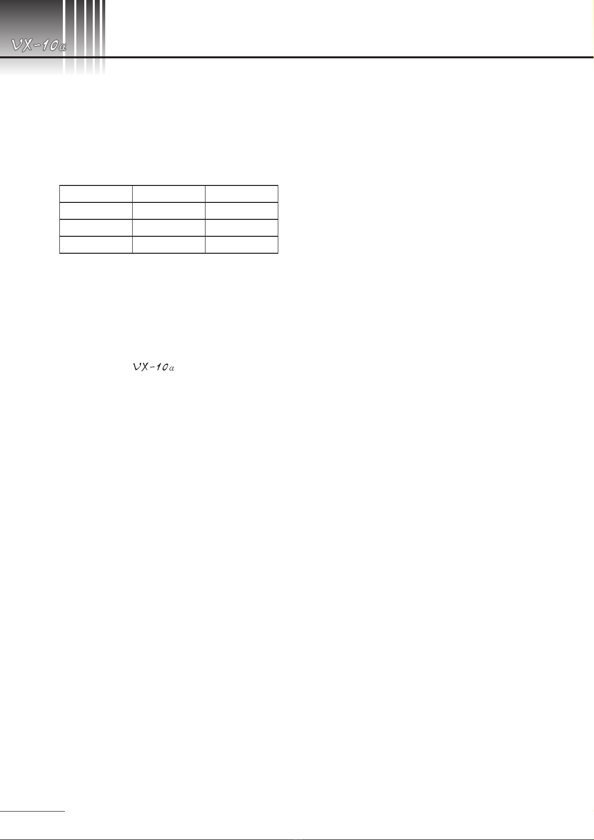
●Install and store the instrument in a place free from
high temperature and humidity, direct sunlight, and
avoid the dusty place. Strictly observe the following en-
vironmental conditions:
In operation
In Transportation, storage
Environmental Temperature
10 to 35°C -15 to +55°C
Relative Humidity
30 to 90% 10 to 95%
Atmospheric Pressure
800 to 1060 hPa 700 to 1060 hPa
●When in use, in storage or in transit, care must be used
to keep the instrument from dewing.
●Place this fundus camera in room, the luminance of
which can be lowered as low as about 5 lx (the lumi-
nance as low as you can barely read a newspaper).
●To keep the instrument dust-free, use the cover
supplied with it when the camera is not in use.
Precautions on electric system
●When the KOWA has not been used for a
long period of time, carry out a daily inspection to de-
termine no defect is present before using it.
●Connect the camera with the power outlet properly so
that the plug might not be pulled out accidentally.
If it should occur, be sure to turn OFF the main switch
before connecting the plug again.
●If irregularity should occur in the circuit in the power
unit, for instance, when you plug in with the main
switch ON, “Err 1” will appear on the display and pho-
tographing will be disabled. In this case, turn OFF the
main switch and wait for a while. Then turn it ON. If
“Err 1”does not appear on the display, you may resume
photography.
●Kowa is not responsible for any failure(s) or damage(s)
caused by improvement, repair or maintenance ren-
dered by the third party other than Kowa and its autho-
rized agent.
●Kowa is not responsible for any failure(s) or damage(s)
caused by improvement, repair, or maintenance ren-
dered using the part(s) other than designated one(s).
●The line voltage should be within ±10% of the rated
value.
●Never change the flash intensity when its flashing is
on.
●To operate switches on the control panel, first turn ON
the main switch and then wait for about 10 seconds
(until the power unit becomes internally stable).
●Do not touch the patient and connectors at the same
time as it may adversely affect the safety.
●Do not turn ON/OFF the main switch in succession.
There should be an interval of 5 seconds or more.
●When plugging or unplugging, turn OFF the main
switch beforehand.
●Do not change the camera back with the main switch
ON.
●The power line from the power outlet must be exclu-
sively connected to the fundus camera.

Introduction
Introduction
P0-7
Precautions: Use of Medical Electrical System
Electrical devices which constitute KOWA system
This instrument constitutes medical Electric system by connecting with the following products.
- Personal computer
It is used in order to acquire the electronic images taken by KOWA . An application software KOWA VK-2 for
instance should be installed on the PC.
LCD monitor or other peripheral equipments are connected to PC.
When you install personal computer in patient environment, please use the below-mentioned “Multi-tap with Isolation Transformer”
.
Precautions for System installation
●All components of this medical electrical system may be installed within a limited patient environment when all
components are installed in accordance with the installation instructions using “Multi-tap with Isolation Transformer”, one
of the system components. And do not use “Multi-tap with Isolation Transformer” in this system for supplying the power
to any components other than this system.
●Prerequisite for installing other components (a PC, printer, video capture printer, video monitor, or other devices) which
do not comply with IEC 60601-1 along with this system is that the electric power to the components is supplied from
“Multi-tap with Isolation Transformer”. The electric power to these components supplied from an electric source other
than Multi-tap with Isolation Transformer (e.g., directly from wall outlets) may cause increased enclosure leakage current
or potential difference between protective grounds, resulting in the injury to the patient or operator. Please use the
“Multi-tap with Isolation Transformer” for supplying the power to the components other than this instrument.
●Any medical electrical equipment that is connected to this system to compose a medical system must comply with IEC
60601-1.
●Any non-medical electrical equipment that is connected to this system to compose a medical system must comply with
safety standards of IEC or ISO provisions applicable to such a non-medical electrical equipment.
●Do not use any additional multi-tap receptacle or extension power cable other than those specified to this system by
KOWA.
●Power supply to this system or “Multi-tap with Isolation Transformer” must be provided individually. (Do not route the
power supply through other multi-tap receptacle to the system or “Multi-tap with Isolation Transformer”.)
●The power cable for an electrical device that compose a medical system must have durability that meets IEC 60245/IEC
60227 or higher standards.
●Assure that the power supply is turned off when connecting an electrical device to the system.
●Do not turn on the power supply until all devices are completely connected.
●Do not place or install the devices and the system components on the unstable or inclined table.
Precautions for “Multi-tap with Isolation Transformer”
●“Multi-tap with Isolation Transformer” should use the one equipped with the rated output more than power consumption
of equipment to connect.
●Do not place “Multi-tap with Isolation Transformer” directly on the floor. Water droplets during room cleaning may enter
the multi-tap resulting in the component failure.
●The power supply cable to “Multi-tap with Isolation Transformer” must be connected to a power receptacle with a
protective ground terminal.
●When using a "Multi-tap with Isolation Transformer" receptacle with a protective ground terminal, read the instruction for
use attached to it to familiarize yourself with the correct use before use.
Daily Maintenance and Cleaning
1. System components
●Wipe the soiled outer surface with soft cloth from which water was firmly squeezed off. Do not wipe the exterior
of the system components with chemicals or solvents such as thinner or benzene. Because LCD monitor screen
covers easily get scratched, lightly wipe with soft cloth such as gauze.
●Refer to the instruction for use provided with each device for details of device maintenance and cleaning.
2. Power cables, connecting cables, and connectors
●Visually verify that all cables have no flaw or damage.
●Visually verify that earth leads of all components and protective ground terminals are securely connected.
●Disconnect the power cables from the power outlet when you do not use the system for a long period of time.
3. Others
●When you change the components of this system, and connection after installing the system, you must build secure
system according to notes currently written here.
●When you add a PC to the system for a archiving purpose, captured images are stored in the hard disk drive of
the PC. Back up the data stored in the hard disk drive regularly since hard disk drives may have a mechanical or
electrical failure.

Introduction
Introduction
P0-8
●Combinations of medical electrical equipment and non- medical electrical equipment
IEC 60601-1 Annex I “ME system aspects” describes the summary of situations that could occur when different combinations
of equipment are used in various medical environments. The brief overview of IEC 60601-1 Annex I is shown below.
Situation No.
Medically used room
Non-
medically
used room
Examples of
possible causes
for exceeding
LEAKAGE
CURRENT limits
Practical means of
compliance
Apply 16.5 in all
situations
Inside the
PATIENT
ENVIRONMENT
Outside the
PATIENT
ENVIRONMENT
1
1a
Items A and B
are ME EQUIP-
MENT
A
IEC
60601
B
IEC
60601
Mains
Plug
Mains
Plug
Multiplied APPLIED
PARTS of the same
type can cause
the total PATIENT
LEAKAGE CUR-
RENT to exceed
limits See Note 1.
- Verify total PA-
TIENT LEAKAGE
CURRENT
1b
Items A and B
are ME EQUIP-
MENT powered
via a MULTI-
PLE SOCKET-
OUTLET
A
IEC
60601
B
IEC
60601
MULTIPLE
SOCKET-OUTLET
Earth conductor
of the MULTIPLE
SOCKET-OUTLET
is broken See also
1a.
- Additional PRO-
TECTIVE EARTH
CONNECTION
(for A or B) or,
- Separating trans-
former
1c
Item A is ME
EQUIPMENT
and B is
Non-ME
EQUIPMENT
A
IEC
60601
B
IEC
XXXXX
Mains
Plug Mains
Plug Due to high TOUCH
CURRENT of B
- Additional PRO-
TECTIVE EARTH
CONNECTION
(for B) or,
- Separating trans-
former (for B)
1d
Item A is ME
EQUIPMENT
and B is
non- ME
EQUIPMENT
powered via
a MULTIPLE
SOCKET-
OUTLET
A
IEC
60601
B
IEC
XXXXX
MULTIPLE
SOCKET-OUTLET
The earth conduc-
tor of the MULTIPLE
SOCKET-OUTLET
is broken or, Due to
high TOUCH CUR-
RENT of B
- Additional PRO-
TECTIVE EARTH
CONNECTION
(for A or B) or,
- Separating trans-
former

Introduction
Introduction
P0-9
Precautions: use of medical electrical system
Situation No.
Medically used room
Non-
medically
used room
Examples of
possible causes
for exceeding
LEAKAGE
CURRENT limits
Practical means of
compliance
Apply 16.5 in all
situations
Inside the
PATIENT
ENVIRON-
MENT
Outside the
PATIENT
ENVIRONMENT
2
2a Items A and
B are ME
EQUIPMENT
No causes of ex-
ceeding LEAKAGE
CURRENT
- No further mea-
sures are neces-
sary
2b Items A and
Item B are ME
EQUIPMENT
powered via
a MULTIPLE
SOCKET-
OUTLET
Earth conductor
of the MULTIPLE
SOCKET-OUTLET
is broken
- Additional
PROTECTIVE
EARTH CON-
NECTION (for A
or B) or,
- Separating trans-
former
2cItem A is ME
EQUIPMENT
and Item B
is non-ME
EQUIPMENT
Due to high TOUCH
CURRENT of B
See rationale for
16.5.
- Do not use metal
connector hous-
ing or,
- SEPARATION
DEVICE
2d Item A is ME
EQUIPMENT
and item B
is non-ME
EQUIPMENT
powered via
a MULTIPLE
SOCKET-
OUTLET
The earth conductor
of the MULTIPLE
SOCKET-OUTLET
is broken
- Additional
PROTECTIVE
EARTH CON-
NECTION (for A
or B) or,
- Separating trans-
former
3
3a Items A and
B are ME
EQUIPMENT
No causes of ex-
ceeding LEAKAGE
CURRENT
- No further mea-
sures are neces-
sary
3b Item A is ME
EQUIPMENT
and item B
is non-ME
EQUIPMENT
Due to high TOUCH
CURRENT of B
See rationale for
16.5.
- Do not use metal
connector hous-
ing for SIGNAL
INPUT/OUTPUT
PART or,
- SEPARATION
DEVICE
3c Item A is ME
EQUIPMENT
and item B in
is ME EQUIP-
MENT or non-
ME EQUIP-
MENT
a) Potential differ-
ence between
PROTECTIVE
EARTH CON-
NECTIONS of A
and B
b) Due to high
TOUCH CUR-
RENT of B
See rationale for
16.5.
- Additional
PROTECTIVE
EARTH CON-
NECTION for
(A), or
- SEPARATION
DEVICE, or
- Do not use
metal connector
housing in the
PATIENT ENVI-
RONMENT
NOTE 1. No causes of TOUCH CURRENT or EARTH LEAKAGE CURRENT exceeding limits.
NOTE 2. IEC 60601: MEDICAL ELECTRICAL EQUIPMENT in compliance with IEC 60601.
NOTE 3. IEC xxxxx: Non-medical equipment in compliance with relevant IEC safety standards.
NOTE 4. Separating transformer: see 16.9.2.1.
NOTE 5. If equipment “B” is outside the PATIENT ENVIRONMENT and if equipment “A” is a CLASS II equipment and has accessible con-
ductive parts connected to the PROTECTIVE EARTH CONNECTON of equipment “B” then additional safety measures could be
necessary, for example: additional protective earth for “B” or separating transformer or SEPARATION DEVICE.
A
IEC 60601
B
IEC 60601
Mains
Plug
Mains
Plug
A
IEC 60601
B
IEC XXXXX
Mains
Plug
Mains
Plug
A
IEC 60601
B
IEC 60601
MULTIPLE SOCKET-OUTLET
A
IEC 60601
B
IEC XXXXX
MULTIPLE SOCKET-OUTLET
A
IEC 60601
B
IEC 60601
Mains
Plug
Mains
Plug
Common protective earth
A
IEC 60601
B
IEC XXXXX
Common protective earth
Mains
Plug
Mains
Plug
A
IEC 60601
B
IEC 60601
B
IEC XXXXX
Mains
Plug
Mains
Plug
Common protective earth Protective earth with
potential difference

Introduction
Introduction
P0-10
Operational (Safety and Hazard prevention) Considerations for
hospital Grade Electrical Equipment
1. Only qualified personnel should operate this equipment.
2. The following items shall be considered when installing equipment.
(1) Install at a location away from water or accidental splashing.
(2) Install at a location which will not be adversely affected by atmospheric pressure, temperature, humidity, ventilation,
sunlight, dust, air containing salt, sulfur and other substances, and the like.
(3) Take care to guard against tilt, vibration and strong impacts, for instance, during transportation.
(4) Equipment must not be installed at locations where chemicals are stored or gasses are generated.
(5) Be careful with the frequencies, voltages and allowable amperes (power consumption) of the power supply.
(6) Make sure that all batteries are installed properly and in good working order (discharging curve, polarity and so forth).
(7) Properly connect ground wires.
3. The following items shall be considered before using the instrument.
(1) Make sure that equipment activates properly after checking switch contact, polarity, dial setting and meters and so forth.
(2) Make sure that the instrument is properly grounded.
(3) Make sure that all cords are properly connected and secured.
(4) Use of other instruments and appliances on the same power circuit is liable to cause errors and incorrect flash output
resulting in incorrect diagnosis or hazards.
(5) Before operations, make sure that the camera back battery is sufficiently charged.
4. The following items shall be considered when using the instrument.
(1) Be sure to minimize the time and quantity required for diagnosis.
(2) Always assure that the equipment and patient are in good condition.
(3) When an abnormality is found on the equipment, take proper measures, for instance, to stop the operation of the
instrument while assuring the patient’s safety.
(4) Do not allow the patient to touch any of the instrument controls.
5. The following items shall be considered after using the instrument.
(1) Turn OFF the instrument after setting control switches, dials, and so forth to their initial statuses following with a
specified procedure.
(2) Do not pull cords for removal because an excessive force is exerted on them.
(3) The following shall be considered regarding storage location.
(a) Store the instrument at locations free from splashes of water.
(b) Store at a location which will not be adversely affected by atmospheric pressure, temperature, humidity, ventilation,
sunlight, dust, air containing salt, sulfur and other substances, and the like.
(c) Take care to guard against tilt, vibration and strong impacts, for instance, during transportation.
(d) Equipment must not be stored at locations where chemicals are stored or gasses are generated.
(4) Clean and rearrange accessories, cords and the like.
(5) The instrument must be cleaned after use so that there will be no problem when using it again.
(6) In case it is expected to be not used for a long period of time, keep the camera back with batteries unloaded from it.
6. If it has some trouble, a label describing the trouble should be affixed on the instrument and contact Kowa
or your Kowa dealer for repair.
7. Equipment shall not be modified.
8. Maintenance
(1) Periodically check the equipment and its components for any abnormality.
(2) When using again the equipment that has not been used for a while, it must be checked beforehand to assure that it is
in normal condition and operates safely.
9. Be careful of the possibility that incorrect operation may be caused by strong electromagnetic waves.
This equipment is examined based on IEC 60601-1-2 (EN 60601-1-2).
The purpose of this standard is to keep safety against the dangerous obstacle in typical medical facilities.
When this equipment is influenced by other equipment, or when it affects other equipment or when there is such fear,
please devise to move this equipment and other apparatus or to make the distance between those equipments.
Moreover, if there is an unknown point, please consult Kowa or your kowa dealer beforehand.

Introduction
Introduction
P0-11
Accessories
Dust cover: 1 pc. Instruction manual: 1 Quick manual: 1 External fixation lamp:
1 pc.
Hexagon wrench:2 pcs. Pin: 2 pcs. Chin rest paper: 1 set Fuse: 2 pcs.
Observation lamp: 1 pc. Blower: 1 pc.
Grip (option) Internal fixation target
(option) Data card: (option)

Introduction
Introduction
P0-12

Introduction
Introduction
P0-13
1
2
3
4
5
6
7
8
9
Summary of equipment
Preparatory procedure
Basic photography
Other practical photography
Handy features
Troubleshooting
Maintenance and inspection
Specifications
Technical references
10
Photochemical Hazard
(ISO 15004)
11
Electromagnetic Compatibility
(IEC 60601-1-2)
KOWAKOWA

ContentsContents
1
2
3
4
5
6
7
8
9
10
11
P0-14
1. Summary of equipment ................... P1-1
1-1 Purpose of use and effectiveness ................P1-1
1-2 General information......................................P1-1
1-3
Intended operator and operating environment
...P1-1
1-4 Features .......................................................P1-1
1-5 System configuration .................................... P1-1
1-6 Name and function of each part ...................P1-2
2. Preparatory procedure..................... P2-1
2-1 Installing .......................................................P2-1
2-2 Connecting to external device ......................P2-1
2-3 Preparatory procedure of fundus camera..... P2-1
2-4 Loading 35-mm camera back’s batteries......P2-2
2-5 Mounting 35-mm camera back.....................P2-3
2-6 Replacing with new 35-mm film.................... P2-3
2-7 Types of available films ................................ P2-4
2-8
Preparatory procedure of the examined eye
..... P2-4
3. Basic photography........................... P3-1
3-1 Operation procedure flowchart .....................P3-1
3-2 Non-mydriatic photography .......................... P3-2
3-3 Mydriatic color photography .........................P3-6
3-4 Mydriatic fluorescein angiography..............P3-10
4. Other practical photography ............ P4-1
4-1 Photography of enlarged image ...................P4-1
4-2 Small pupil photography
..................................
P4-1
4-3
Red-free photography (mydriatic color mode)
...P4-2
4-4 Photography of data card .............................P4-3
4-5 Blue Eye button ............................................P4-3
5. Handy features ................................ P5-1
5-1 LCD monitoring mode
(“mydriatic color” and “FA” mode)....................... P5-1
5-2 External image input display function...........P5-2
5-3 Changing initial settings................................P5-3
6. Troubleshooting ............................... P6-1
7. Maintenance and inspection............ P7-1
7-1 Daily maintenance........................................P7-1
7-2 Daily inspection
(items that requires user’s inspection)......... P7-1
7-3 Inspecting/cleaning the objective lens..........P7-2
7-4 Disinfect........................................................P7-2
7-5
Replacing observation lamp with a new one
...
P7-3
7-6 Replacing flash lamp with a new one ...........P7-4
7-7 Replacing fuse with a new one..................... P7-5
7-8 Fitting chin rest paper...................................P7-5
7-9 Replenishing consumables...........................P7-5
7-10 Periodical Inspection .................................... P7-6
7-11 Repairing the Instrument .............................. P7-6
7-12 KOWA Daily Inspection Table...... P7-6
8. Specifications .................................. P8-1
9. Technical references........................ P9-1
10. Photochemical Hazard
(ISO 15004) ................................. P10-1
11. Electromagnetic Compatibility
(IEC 60601-1-2)............................P11-1
Introduction............................................................................................................................ P0-1
Operational considerations for safety.................................................................................... P0-1
Indication of caution label...................................................................................................... P0-5
Precautions in operation........................................................................................................ P0-6
Precautions: Use of Medical Electrical System ..................................................................... P0-7
Operational (Safety and Hazard prevention)
Considerations for hospital Grade Electrical Equipment ..................................................... P0-10
Accessories ..........................................................................................................................P0-11

Summary of equipment
1
P1-1
1-1 Purpose of use and effectiveness
KOWA is intended for taking pictures of fundus images with mydriatic or without mydriatic.
1-2 General information
This equipment is a fundus camera which is capable of mydriatic and non-mydriatic photography with two angles of
view: 50° and 30° (45° and 27° for non-mydriatic photography). You can record photographic data with 35-mm film,
video and so forth.
1-3 Intended operator and operating environment
A person who operates this instrument should have received introductory education of Retinal Camera, and should
have specialized knowledge of ophthalmic care.
Please use this instrument indoor without a bright light which causes miosis of pupil of patient.
1-4 Features
1) A single operation of the instrument allows you to select non-mydriatic color, mydriatic color, or mydriatic
fluorescent photography.
2) Design for small size, lightweight and power-saving taking into account the service environment of equipment.
3) Automatic exposure system which can be automatically linked with a camera in use.
4) Wide-range flash of 0.6WS to 300 WS (19 steps) for fully handling film/digital image recordings.
5) Switch at hand which enables automatic insertion of exciter filter and barrier filter.
6) Switch at hand which enables switching to diopter lens for compensating the examined eye.
7) Working distance guiding function and focus detecting function, enabling flare-less, sharp pictures to be taken.
8) Small pupil mode to cope with insufficient pupil’s diameter in mydriatic photography (not for non-mydriatic pho-
tography).
9) LCD monitoring mode for readily enabling mydriatic photography without an attempt to look through a optical
viewfinder (switch to infrared illumination).
10) Digital camera can be connected if combined with a filing device.
11) Easy-to-see panel display which will indicate only available switches in each mode.
1-5 System configuration
Video camera connecting
adapter (option; for KD-211C,
DXC-990 or digital SLR camera)
35-mm camera back
Main camera unit
Base / power unit
External fixation lamp

Summary of equipment
1
1. Summary of equipment
P1-2
1-6 Name and function of each part
Objective lens
A large aspherical lens with protective lens cap
for keeping lens surface from dirt and dust.
Focusing knobs
Knobs located on both sides of main camera
unit for fine focusing adjustment.
F.D. switch
Used to switch ON/OFF the luminous lines of
focus detection aid (available in mydriatic mode
only).
W.D. switch
Used to turn ON/OFF the detecting luminous
dots for camera alignment (available in mydri-
atic mode only).
Upper camera back mount (video mount)
A mount for fixing video camera adapter.
Optical viewfinder(eyepiece)
Adjustable to the photographer's eye dioptric
power in a range of -8D to +5D (a double-cross
reticle is incorporated for focusing).
Because fundus image must be brought to the
focus point of optical viewfinder, the photogra-
pher must adjust the optical viewfinder to his or
her eye beforehand.
Lower camera back mount (35-mm mount)
A mount for fixing 35-mm camera back. Cord-
less connection provided of the camera back to
the main camera unit.
Cap for flash lamp releasing pin
Upon removal of this cap, a red-marked base
will appear. A simple press on the base will
cause the flash lamp to be released. Before re-
placement, be sure to turn off the power switch.
Shutter button
Pressing this button causes the flash lamp to
energize and shooting is complete.
Control lever
A stick lever for moving the main camera unit
both laterally and longitudinally so that the inci-
dent light can enter the examined eye properly.
"Camera height adjusting handle
Handle for moving main camera unit vertically
so that the incident light can enter the examined
eye properly.
#Power switch
l : ON O : OFF
$Fuse holders
D
E
1
2
3
4
5
6
7
8
9
0
A
BC
H
F
G
I
J
K

Summary of equipment
1
1. Summary of equipment
P1-3
%Power cord
The shape of the plug varies according to the
input voltage.
&External fixation lamp
Used to guide the examined eye's fixation to
desired direction.
'Forehead rest
Used to rest and fix the patient's forehead
against it.
(Chin rest
Used to rest and fix the patient's chin on it.
)Head fixation band
Used to secure patient's head in case his or her
face is likely to move (e.g. child patient).
*Chin rest handle
Used to raise/lower the chin rest.
+Eye level mark
The vertical position of examined eye must be
aligned with this mark.
,Fitting part of internal fixation target
Fit internal fixation target (optional) at its mount.
-Field angle knob
Used to select a field angle of either 50°or 30°
(45°or 27°for non- mydriatic photography).
.Data card slot
An insertion slot for written data card to be pho-
tographed.
/Filter inserting slot
Used for inserting optional green filter after re-
moving the rubber cap.
0Light source cover fixing screws
Upon removal of this cover and inner cover,
flash lamp and observation lamp will appear al-
lowing replacement.
Be sure to turn off the power switch before re-
placement.
1LCD monitor
In non-mydriatic mode,the examined eye is con-
tinuously observed on this monitor so that the
fundus camera can be properly guided.
This monitor can also be used to check the im-
ages photographed.

Summary of equipment
1
1. Summary of equipment
P1-4
2Horizontal lock lever
Upon operation of this lever, the rotating arm will
be locked.
3Tilting handle
By turning this handle, the main camera unit will
be tilted vertically.
4Lock handle
By turning this handle, the tilting handle will be
locked.
5Lock lever
Upon operation of this lever, the base will be
locked.
6Display screen
Timer's count is indicated increasing 0.1 second
at a time on the screen with 5 digits.
When timer is not in work, flash intensity and
error will be indicated.
7Observation lamp indicating lamp
The lamp indicates the location of the observa-
tion light intensity control knob.
8Flash intensity compensation indicating lamp
These lamps indicate flash intensity compensa-
tion.
9Observation light intensity control knob
Used to adjust observation light intensity.
:Flash intensity compensation knob
Used to adjust flash intensity level.
;Working camera back indicator
This indicator comes on indicating which cam-
era back of upper or lower ones is in work,
linking with the camera back select switch.
When camera back is not loaded on a selected
camera back mount, the indicator will come off.
When film is not loaded on the 35-mm camera
back, it will flash.
<Camera back select switch
Used to select the optical paths, lower(35-mm)
or upper(Electronic images).
=Mydriatic fluorescein angiography select but-
ton
Used to select mydriatic fluorescein angiogra-
phy mode.
>Mydriatic color button
Used to select mydriatic color photography
mode.
Other manuals for VX-10a
1
Table of contents
Other Kowa Laboratory Equipment manuals
Popular Laboratory Equipment manuals by other brands

Westlab
Westlab 665-251 manual

Insphero
Insphero Akura 384 ImagePro quick start guide

Thermo Scientific
Thermo Scientific Fisherbrand GT4 instruction manual

PCE Health and Fitness
PCE Health and Fitness PCE-MSR 340 user manual

Cascade Sciences
Cascade Sciences CVO-2-HT Installation and operation manual

Sigma
Sigma 4-5KRL manual

ESPEC
ESPEC SU Series installation guide

Kinematica
Kinematica POLYTRON PT 3100 D operating manual

THORLABS
THORLABS Telesto Series user manual

World Precision Instruments
World Precision Instruments KITE Care and maintenance

Agilent Technologies
Agilent Technologies 7820A Advanced user's guide

Cole Parmer
Cole Parmer MP-200 Series instruction manual