Koyker KB660 User manual

OWNERS MANUAL
MANUAL NO. 760168
KB660
BACKHOE
IMPORTANT-KOYKER DEALER
BE SURE THIS MANUAL IS GIVEN TO THE
PURCHASER FOR FUTURE REFERENCE
KOYKER MANUFACTURING CO., P.O. BOX 409
LENNOX, SD 57039
10/13/08

CONTENTS
CONTENTS PAGE
Introduction................................................................................................................................................1
SAFETY INFORMATION
Safety Alert Symbol...................................................................................................................................2
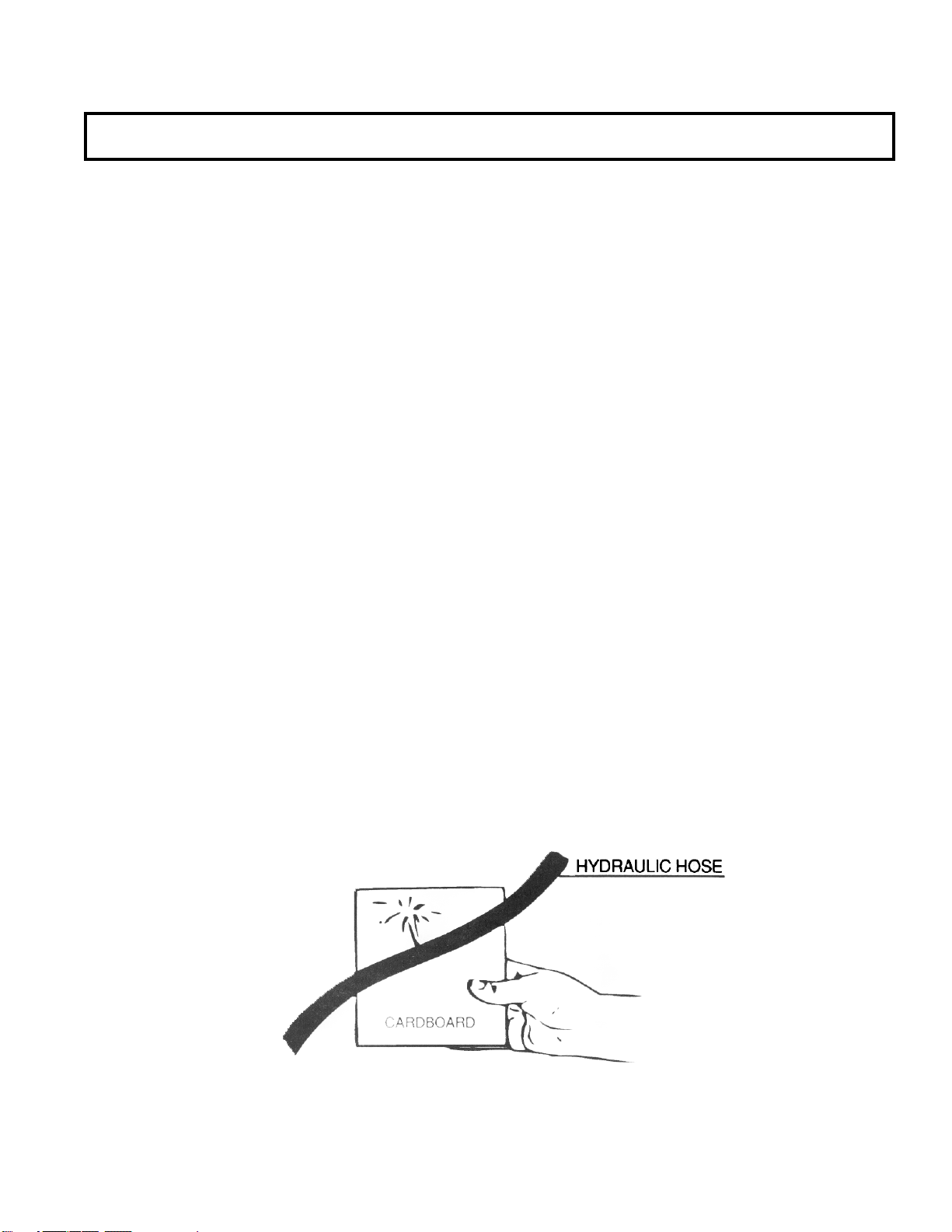
Safety Information ...................................................................................................................................3-5
Safety Decals .............................................................................................................................................6
OPERATING INSTRUCTIONS
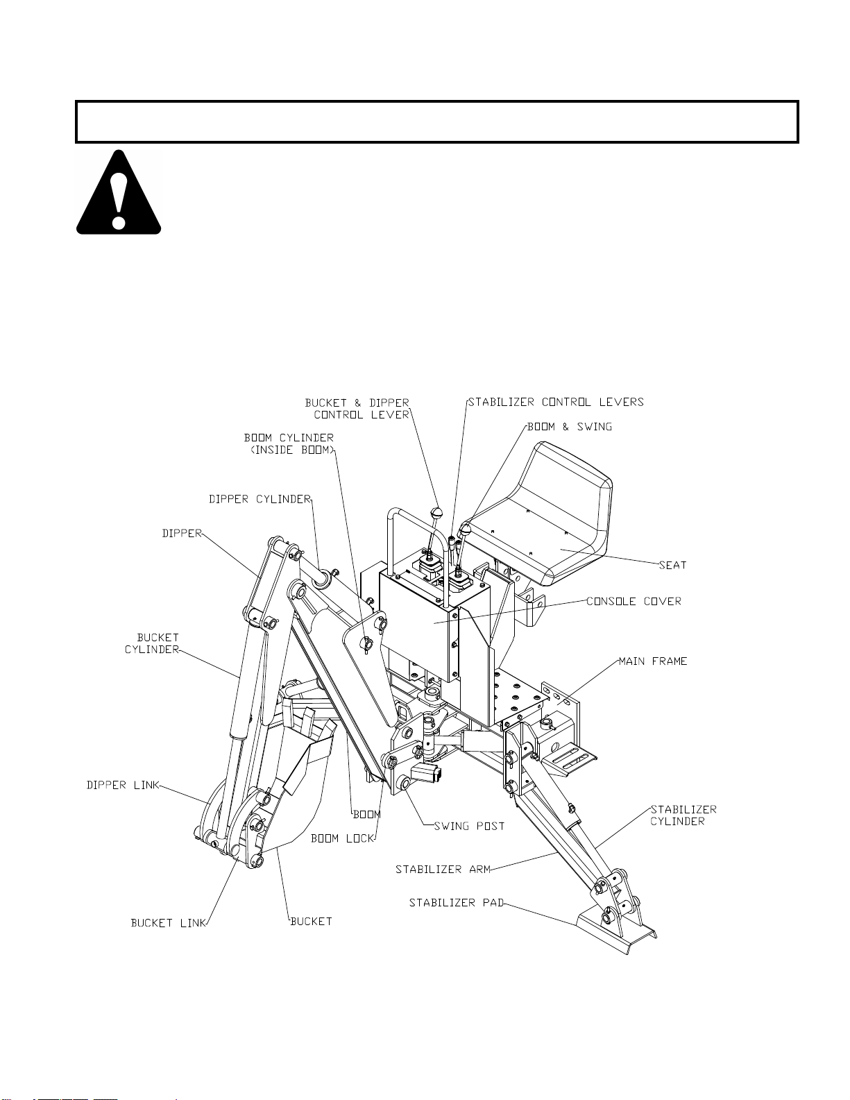
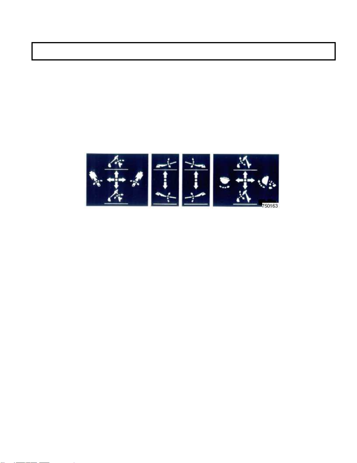
Operation.................................................................................................................................................7-14
SERVICE AND MAINTENANCE
Backhoe Inspection, Service, and Maintenance ....................................................................................15-17
Hydraulic Hose Parts Diagram ................................................................................................................18
Hydraulic Hose Part Schedule..................................................................................................................19
Valve Parts Diagram.................................................................................................................................20
Valve Part Identification Schedule ...........................................................................................................21
In Line Filter Parts Diagram .....................................................................................................................22
Backhoe Main Frame Parts Diagram........................................................................................................23
Backhoe Main Frame Parts Schedule.......................................................................................................24
Backhoe Arm Frame Parts Diagram.........................................................................................................25
Backhoe Arm Frame Parts Schedule ........................................................................................................26
Bucket Parts Diagram and Schedule.........................................................................................................27
Bucket Replacement Teeth Diagram and Schedule..................................................................................28
3-Point Mount Diagram and Schedule......................................................................................................29
Drawbar Stabilizer Diagram and Schedule...............................................................................................30
PTO Hydraulic Diagram...........................................................................................................................31
PTO Hydraulic Schedule ..........................................................................................................................32
Torsion Bar Diagram and Schedule..........................................................................................................33
Hydraulic Information ..............................................................................................................................34
2” Cylinder Service Kit Schedule.............................................................................................................35
2 1/2” Cylinder Service Kit Schedule.......................................................................................................36
Hydraulic Cylinder Part Diagram.............................................................................................................37
Piston and Gland Service Diagram...........................................................................................................38
LIMITED WARRANTY INFORMATION
Limited Warranty...................................................................................................................................39-41
TORQUE SPECIFICATIONS
Torque Specifications ...............................................................................................................................42

INTRODUCTION
During a considerable period of time, Koyker Manufacturing Company of Lennox, South Dakota, made a
study of the backhoe industry and concluded that the person needs a backhoe that provides quality,
dependability, few parts, ruggedness, good delivery, and ease of maintenance, all at a fair price. The
KB660 backhoe has achieved these goals. With proper care and handling, it will give many years of good
service in normal operations.
Please be sure to follow the manual for proper care instructions.
TO THE PURCHASER
You have purchased an excellent product. With proper care and use, it will give you years of good safe
service. Use only KOYKER or KOYKER approved parts in the general maintenance and repair of your
equipment. Please fill out ownership registration card as soon as possible.
Should you have any questions, comments, improvements, or suggestions regarding the contents of the
manual provided, please contact Koyker Manufacturing Company (800-456-1107 or E-mail
koyker@koykermfg.com).
We care about your safety!
Remember ALL safety decals are no charge from the factory. Please replace all safety decals if
damaged or missing. Your safety is important to us.
Page 1

SAFETYALERT SYMBOL
The symbol shown below is used to call your attention to instructions concerning your personal safety.
Watch for this symbol it points out important safety precautions. It means ATTENTION! Become Alert!
Your Personal Safety Is Involved!
Read the message that follows and be alert to the possibility of personal injury or death.
DANGER: Indicates an imminently hazardous situation that, if not avoided, will result in death or serious
injury.
WARNING: Indicates a potentially hazardous situation that, if not avoided, could result in death or
serious injury.
CAUTION: Indicates a potentially hazardous situation that, if not avoided may result in minor or
moderate injury.
WARNING!
Anyone who will operate or work around a backhoe should first read this manual.
Page 2

SAFETY
Improper use of a backhoe can cause serious injury or death. The following safety precautions, and those
given on the tractor mount installation instructions, should be thoroughly understood before attempting to
operate this machine.
BEFORE OPERATING:
Carefully study and understand this manual, the specific tractor mount instructions, and the
attachment(s) manual's).
Prior to operation, inspect the backhoe for system leaks and damaged, missing, or malfunctioning
components in an effort to avoid the possibility of a dangerous failure involving structural members
or hydraulic system components.
Be certain any repairs necessary are completed prior to backhoe operation. Set the parking brake,
place the gear shift in neutral, turn off the tractor and remove the key.
Never operate or transport unit with covers or shields removed.
Never leave the tractor running unattended.
Completely familiarize yourself and others involved with the operation of the hydraulic control
valve before operating the backhoe.
Be certain all bystanders are clear of the machine and operation area prior to operation.
It may be necessary to add wheel ballast or front weights as recommended by the tractor
manufacturer to maintain stability of the machine to prevent tipping or upset which could result in
serious injury or death.
It is recommended that both front and rear wheel treads be set to the widest recommended width to
prevent tipping or upset which could result in serious injury or death.
Do not take passengers on the tractor or backhoe. There is no safe place for a passenger.
Use the handholds and step plates when getting on/off the tractor. Failure to do so could cause a
fall.
This backhoe is designed for light excavating, light commercial, or light grading and digging. It’s
design is NOT intended for industrial use.
DURING OPERATION:
Never operate the backhoe by standing up on, or beside the machine. Operate only from the
backhoe seat.
Page 3

SAFETY
Check your work area. Avoid hitting overhead electrical wires, underneath cables, pipes, gas lines
and etc.
Be sure operating area is clear of others during machine operations.
Never lift, hoist, or carry humans in the bucket or on any portion of the backhoe or backhoe
attachments. Failure to heed, may result in serious injury or death.
Do not adjust relief valve setting. This valve is factory set and should be adjusted only by a
qualified service person. Incorrect valve setting could result in equipment damage and/or personal
injury.
Block off work area from all bystanders, livestock, etc. Allow plenty of room for backhoe reach
and swing.
Operate only from the backhoe seat.
Use your backhoe only for digging. Do not use it to pull things, as a battering ram, or attach ropes,
chains, etc., to the unit.
Lower stabilizers and bucket when removing backhoe. This will increase the stability of the unit.
Do not dig close to stabilizers, the ground could collapse from under the backhoe.
Do not lift loads in excess of the backhoe capacity.
Always lower the backhoe bucket and stabilizers to ground, shut off engine, remove key and apply
the parking brake before leaving the unit unattended.
TRANSPORTING:
Be sure to engage the boom lock before transporting backhoe. Failure to do so could cause an
unstable traveling condition.
Allow for height of backhoe when transporting backhoe so as not to catch unit on low overhangs or
wires.
Use safety lights and SMV emblem in addition to whatever local codes require when equipment is
being transported on the road or highway. Check with proper authorities for legal limitations.
Do not drive close to ditches, excavations, etc. cave in could result. Drive slow over rough terrain.
Page 4

SAFETY
PERFORMING MAINTENANCE:
Carefully review, understand, and follow the “maintenance” section in this owners manual before
attempting to service backhoe. Observe proper maintenance schedules and repairs to keep unit in
safe working order. See on page 15.
Lower the bucket or attachment to the ground, shut off tractor engine, and relieve pressure in the
hydraulic system before adjusting, lubricating, or servicing the backhoe.
Escaping hydraulic oil under pressure can penetrate the skin. Never use any part of your body to
check for hydraulic leaks. Use cardboard when checking for leaks. See Fig. 5-1. Relieve hydrau-
lic pressure before disconnecting any hydraulic line. Failure to heed may result in serious injury or
death.
Before disconnecting hydraulic lines, lower the backhoe and attachments. Lock out the hydraulic
supply and relieve all hydraulic pressure.
Replace any damaged or painted-over decals. See Page 6 for replacement decals.
REMEMBER:
1. Move Slowly!
2. Always use care and common sense!
3. Be careful for your own sake and for that of others!
4. Koyker Mfg. Co. includes all reasonable means for accident prevention except a safe and
careful operator.
FIG. 5-1
Page 5

SAFETY DECALS
Page 6

WARNING:
Never allow anyone to operate the backhoe until they have carefully reviewed and
understood this owners manual.
GENERAL INFORMATION:
Throughout this manual, reference is made to various backhoe components. The purpose of this page is to
acquaint you with the various names of these components. This knowledge will be helpful when reading
through this manual or when ordering service parts.
OPERATION
Page 7

GENERAL INFORMATION
Your backhoe is operated by four different control levers. Two are for stabilizers operation and the other
two operate the swing, boom, dipper, and bucket functions. The information contained below will help
you become familiar with the operation of each control lever. Read the safety precations of this manual
before attempting to use the backhoe. Remember, right and left when referred to on this page are
determined by the operator’s position seated at the backhoe controls facing the bucket.
BOOM/SWING LEFT RIGHT DIPPER/BUCKET
CONTROL LEVER STABILIZER CONTROL LEVER
BACKHOE STABILIZER LEVERS
Moving the stabilizer lever (s) forward will bring the backhoe stabilizer (s) “Down”. Moving the stabilizer
lever (s) rearward will bring the backhoe stabilizer (s) “Up”. Both stabilizers are required to be down for
proper stability of the backhoe when in operation.
BOOM/SWING LEVER (LEFT HAND LEVER)
Pushing the boom/swing lever forward will “Lower” the boom dipstick and bucket. Pulling the lever
rearward will “Lift” the boom dipstick and bucket.
Pushing the boom/swing lever to the left will swing the boom and bucket to the “Left”. Pushing the lever
to the right will swing the boom and bucket to the “Right”.
DIPPER/BUCKET LEVER (RIGHT HAND LEVER)
Pushing the dipper/bucket lever forward will move the dipper “Out” or away from the operator. Pulling
the dipper/bucket lever rearward will move (crowd) the dipper “In” or toward the operator.
Pushing the dipper/bucket lever to the left will “Fill” or curl the bucket (move inward). Pushing the lever
to the right will “Dump” the bucket (move outward).
OPERATION
Page 8

GENERAL INFORMATION
When operating the backhoe, smoothness of technique should be strived for at all times. Smoothness will
come with experience and practice at feathering the controls. Establish a flowing digging cycle to increase
operator efficiency and save unnecessary wear on the machine.
Observe the following points to obtain the best results and to fully utilize the digging force of the backhoe.
WARNING! Operate the backhoe only when seated at the controls. Any other method could result
in serious personal injury or death.
Never attempt to drive the tractor when seated at the backhoe controls.
Check the prospective digging area for hidden utility lines before operating the
backhoe or when in doubt of their location, contact the local utility companies. When
operating the backhoe in an area where utilities are expected to be present, throttle the
backhoe down and proceed with caution. If you feel the backhoe bucket made contact
with anything out of the ordinary, stop digging at once. If a utility line has been
damaged, contact the utility at once.
BEFORE YOU START DIGGING
Before any excavating is started, it is always a good idea to plan out the job first. Various things need to
be considered and taken into account prior to the actual digging. The operator should inspect the job site
and take notice of any potential hazards in the area. He should have a complete understanding of the tasks
he is expected to perform. Figure out what will be done with the spoil (excavated soil) will it be used to
backfill or be trucked out? What are the soil conditions like? Will you have to work around others? Etc.
Once you have become familiar with the jobs site and understand the job requirements, it is time to set up
for the actual digging. Position the backhoe in such a way as to minimize repositioning the unit and to
maximize digging efficiency. Consider the placement of spoil and position the backhoe to be able to dig
the maximum amount of soil, accurately, while leaving enough room for the spoil removed to be piled in
the desired area.
OPERATING INSTRUCTIONS
Page 9

BEFORE YOU START DIGGING (CONTINUED)
Once the unit is positioned, lower the stabilizers to the ground. The tires should still be
supporting most of the vehicle weight with the stabilizers relieving only part of the weight, and mainly
acting to give the unit a wider base for increased stability and to keep the unit from moving or bouncing
with backhoe use. The front end loader should also be lowered if the unit is so equipped. The vehicle
should at no time be supported by the stabilizers and loader with any of it’s wheels off the ground. Severe
damage to the vehicle could result. When operating the unit on a delicate surface (such as concrete, or
stone work) or on sandy, loose, or soft ground place plywood under the stabilizers to help distribute the
load over a wider area.
OPERATING INSTRUCTIONS
Page 10

BASIC DIGGING TECHNIQUE
When starting an excavation, make the first cut of each section shallow, being careful to follow the exact
layout of the excavation. The reason for shallow cut is to minimize damage to the sod and to facilitate
replacement. These first cuts are also important because they will act as guides for the remaining cut, thus
getting the first few cuts as accurate as possible will help in keeping all future cuts accurate.
When digging with the backhoe, extend the boom, dipper and bucket out, away from the operator. Lower
the boom and dipper to start the digging process. The bucket teeth should be at a 30 to 45 degrees entry
angle. As the digging starts, curl the bucket until the cutting is level with the horizon. Crowd the bucket in
toward the operator, manipulate the boom lever to keep the bucket level. As the bucket moves toward the
operator, manipulate the boom lever to keep the cut lever. At the end of the digging cycle, crowd the
dipper in and completely curl the bucket while lifting it from the excavation. Once you have cleared the
excavation, swing the bucket to the spoil pile. Start to dump bucket before the pile is approached. Once
the bucket is empty, swing the unit back to the excavation, positioning the bucket and dipper for the next
cut in the process. The whole digging process should be one smooth cycle that is repeated until the
excavation is completed.
When the excavation has been dug to
within six inches of the finished bottom,
clear and touch up the sides of the
excavation. Use the flat sides of the
bucket to scrape off any high spots.
Dislodge any exposed rocks if they seem
loose. When finishing the walls, finish
the far wall by curling the bucket out,
crowing the dipper out, and forcing the
bucket down. To finish the closest wall,
lift the bucket up and curl it in.
OPERATING INSTRUCTIONS
Page 11

EXCAVATING ON SLOPES
When digging on slopes always face the backhoe upgrade whenever possible. It may be necessary to
cut a level surface in the hill for the backhoe to sit in when operating on slopes. This will allow the
backhoe to sit in level for digging the main excavation. Pile the spoil from the surface downhill. When
digging the main excavation, pile the spoil uphill.
OPERATING INSTRUCTIONS
Page 12

TRANSPORTING
Follow the simple steps listed below when preparing the backhoe for transporting between work sites.
1. Before transporting the backhoe, raise the boom, dipper, and bucket to transporting position.
2. Engage the boom lock to lock the boom to the swing post in the transporting position. Replace
lock pins to secure boom lock. See in Fig. 1-1
3. Raise all stabilizers.
CAUTION! Be sure to install a SMV (Slow Moving Vehicle) sign on the backhoe dipper
before attempting to transport the backhoe.
When transporting the backhoe on a road or highway at night or during the
day, use accessory lights and devices for adequate warning to the operators of
other vehicles. In this regard, check local government regulations.
Always drive slowly over uneven terrain to avoid tipping the backhoe.
Fig. 1-1
OPERATING INSTRUCTIONS
Page 13

Page 14
3-Point Mount Removal
Position tractor on a hard level surface, remove swing lock pin and transport bar, and center the backhoe
boom.
Lower stabilizers and take weight of backhoe off of rear tractor tires.
Lower boom and dipper to form 90-degree angle and rest bucket on the ground.
Remove pin that attaches top link to tractor. Remove lower 3-point arms from backhoe. Place blocks un-
der mainframe and raise stabilizers to lower backhoe mainframe onto blocks. Block backhoe as neces-
sary to make it stable.
OPERATING INSTRUCTIONS
Pre-Operation Check List
(Owner’s Responsibility)
The operator should perform the following check list before operating backhoe.
•
Check that backhoe is properly and securely attached to tractor.
•
Make sure all hydraulic connections are tight and all hydraulic lines and hoses are in good conditions
before engaging tractor PTO.
•
Check that there are no leaks in the hydraulic system. Before operating, all hydraulic hoses must be
routed properly and not be twisted, bent, sharply, kinked, pulled tight or frayed.
•
During inspection, check that all nuts, bolts, and pins are secure.
•
Make sure only original equipment high-strength top link pin, provided with tractor, is used to attach
top link to tractor.
•
Make sure tractor lower lift arm stabilizers (blocks or chains) are positioned to prevent lift arms and
backhoe from swaying.
•
Place all backhoe controls in neutral position before starting tractor engine.
•
Check hydraulic reservoir level.
•
Grease all pivot points.
•
If backhoe is mounted on tractors 3-pt and the tractor is equipped with a draft function make sure to
lock out or set the draft control to zero before digging.

BACKHOE INSPECTION, SERVICE, AND MAINTENANCE
Lower the bucket to the ground, shut off tractor engine, and relieve the pressure in the hydraulic
system before adjusting, lubricating, or servicing the loader.
Inspect all pins and grease fittings before each use. Lubricate with heavy duty grease as indicated
in this manual.
Periodically check all bolts for looseness and re-torque if necessary.
Before storage, be certain all hydraulic cylinders are fully collapsed so that the rod will not be
exposed to the elements or damaged.
Be certain hydraulic system remains sealed at all times to prevent contamination.
Check and maintain an adequate fluid level in the tractor reservoir prior to use.
Inspect all hydraulic system hoses and fittings. Replace prior to further operation if damaged.
WARNING!
Escaping hydraulic oil under pressure can penetrate the skin. Never use body to
check for hydraulic leaks. Use cardboard when checking for leaks. See Fig. 12-1.
Relieve hydraulic pressure before disconnecting any hydraulic line. Failure to heed
may result in serious injury or death.
FIG. 12-1
Page 15

BACKHOE INSPECTION, SERVICE, AND MAINTENANCE
Page 16
KEY:
“S” = REQUIRED SERVICE HOURLY INTERVAL (Continue repeating service intervals)
“I” = PERFORM AT INITIAL BREAK-IN (Thereafter at hour interval shown)
“A” = ANNUALY OR AT HOURLY INTERVAL (Whichever occurs FIRST)
Hourly Service Interval
Periodic Service Daily 8 16 24 50 100 200
Pivot ends (Excessive wear) S
Check hydraulic reservoir level S
Check/tighten hardware I S
Tighten and torque wheel bolts I S
Check Hydraulic fittings and lines I S
Check pins, bushings, and zerks A
Grease zerks S S
Clean out debris from operator compart-
ment S
See your Koyker dealer for the following services:
Change Hydraulic Oil & Filters I A

BACKHOE INSPECTION, SERVICE, AND MAINTENANCE
Hydraulic Pump System (Optional)
Check the fluid level in reservoir before operating daily. Change oil and filter after first 20 hours of
operation and then every 200 hours after or annually , which ever is first. In extremely dry or dirty
conditions, more frequent servicing may be necessary. Contamination will shorten the life of hy-
draulic components.
Recommended Oils and Temperature Ranges.
Do not exceed 180º F.
Do not mix oil types or grades.
SAE Hydraulic ………………….. All Temperatures
Transmission Fluid
Type “A” or “F” ATF …………… All Temperatures
SAE 30-30W …………… ………. 90º F and Above
SAE 20-20W …………… ………. 35º - 90º F
ASAE 10-10W …………… …….. 35º F and Below
Page 17
OIL SPECIFICATIONS AND CAPACITYS
IMPORTANT
Fill reservoir with new hydraulic fluid only. Do not mix oil types or grades.
Engage PTO pump and run at idle for 5 minutes. Check fluid level and add as necessary.
Gear Box .......................................................1 Pint
80-90W
Hydraulic Tank .............................................4 Gallons
Cylinders and Hydraulic lines.......................2 Gallons
NOTE: The Backhoe is shipped from the factory with oil in the cylinders, hydraulic lines and Hydraulic
Tank (if equipped). If there is a need to add oil, use Mobil 424 hydraulic fluid or equivalent only.

HYDRAULIC SYSTEM PARTS DIAGRAM
Page 18
AB CD EF GH IJ KL MN
Table of contents
Other Koyker Farm Equipment manuals