KRACK KR Series User manual

KR Series
UNIT COOLERS
Installation and Operation Manual
Products that provide lasting solutions.
Part Number: E108318_S

KR Electrical Defrost Unit Coolers (PN E108318_S) 1
BEFORE YOU BEGIN
Read the safety information completely and carefully.
MISE EN GARDE
AVERTISSEMENT
MISE EN GARDE
AVERTISSEMENT
* * * * * * * * * * * * * * * * * * * * * * * * * * * * * * * * * * *
Environmental Concerns
Hussmann recommends responsible handling of
refrigerants that contain Chlorine, Fluorine and
Carbon (CFCs) and those that contain Hydrogen,
Chlorine, Fluorine, and Carbon (HCFCs). Only certied
technicians may handle these refrigerants.
All technicians must be aware and follow the
requirements set forth by the Federal Clean Air
Act (Section 608) for any service procedure being
performed on this equipment that involves refrigerant.
Additionally, some states have other requirements that
must be adhered to for responsible management of
refrigerants.
Contractors shall strictly adhere to specifications
provided by the Engineer of Record (EOR), as well
as US Environmental Protection Agency regulations,
OSHA regulations, and all other federal, state and
local codes. This work should only be done by
qualified, licensed contractors. There are numerous
hazards, not limited to, but including: burns due to
high temperatures, high pressures, toxic substances,
electrical arcs and shocks, very heavy equipment
with specific lift points and structural constraints, food
and product damage or contamination, public safety,
noise, and possible environmental damage. Never leave
operating compressors unattended during the manual
soft-start process. Always power rocker switches off
when unattended.
PERSONAL PROTECTION EQUIPMENT (PPE)
Only qualied personnel should install and service
this equipment. Personal Protection Equipment (PPE)
is required whenever servicing this equipment. Wear
safety glasses, gloves, protective boots or shoes,
long pants, and a long-sleeve shirt as required when
working with this equipment. Observe all precautions
on tags, stickers, labels and literature attached to this
equipment.
The precautions and use of the procedures described
herein are intended to use the product correctly and
safely. Comply with the precautions described below
to protect you and others from possible injuries. Relative
to their potential danger, the relevant matters are divided
into four parts as defined by ANSIZ535.5
ANSI Z535.5 DEFINITIONS
• DANGER – Indicate[s] a hazardous
situation
which, if not avoided, will result in death or
serious injury.
• WARNING –Indicate[s] a hazardous
situation
which, if not avoided,
could result in death or
serious injury.
• CAUTION –Indicate[s] a hazardous
situation
which, if not avoided, could result in minor
or moderate injury.
• NOTICE – Not related to personal injury –Indicates[s]
situations, which if not avoided, could result in damage
to equipment.
!
!
!
CAUTION
WARNING
CAUTION
WARNING
!
!
!
!
!
!

2KR Electrical Defrost Unit Coolers (PN E108318_S)
— LOCK OUT/TAG OUT —
To avoid serious injury or death from electrical
shock, always disconnect the electrical power at
the main disconnect when servicing or replacing
any electrical component. This includes, but is not
limited to, such items as controllers, electrical panels,
condensers, lights, fans, and heaters.
CAUTION
WARNING
This manual was written in accordance with
originally perscribed equipment that is subject to
change. Hussmann reserves the right to change all
or part of the equipment for future stores such as,
but not limited to, controllers, valves and electrical
specifications. It is the installers responsibility to
reference the refrigeration drawings supplied for
each installation, as directed by the Engineer of
Record.
CAUTION
WARNING
Proper Field Wiring and Grounding Required!
Failure to follow code could result in death or
serious injury. All field wiring MUST be performed
by qualified personnel. Improperly installed
and grounded field wiring poses FIRE and
ELECTROCUTION hazards. To avoid these
hazards, you MUST follow requirements for field
wiring installation and grounding as described in
NEC and your local/state electrical codes.
CAUTION
WARNING
This warning does not mean that Hussmann products
will cause cancer or reproductive harm, or is in
violation of any product-safety standards or
requirements. As clarified by the California State
government, Proposition 65 can be considered more of
a‘right to know’ law than a pure product safetylaw.
When used as designed, Hussmann believes that our
products are notharmful. We provide the Proposition
65 warning to stay in compliance with California State
law. It is your responsibility to provide accurate
Proposition 65 warning labels to your customers when
necessary. For more information on Proposition 65,
please visit the California State government website.
August 31, 2018
This equipment is prohibited from use in California
with any refrigerants on the “List of Prohibited
Substances” for that specific end-use, per California
Code of Regulations, title 17, section 95374.
Use in other locations is limited to refrigerants
permitted by country, state, or local laws and is the
responsibility of the installer/end-user to ensure only
permitted refrigerants are used.
This disclosure statement has been reviewed and
approved by Hussmann and Hussmann attests,
under penalty of perjury, that these statements are
true and accurate.
CAUTION
WARNING
This warning does not mean that Hussmann
products will cause cancer or reproductive
harm, or is in violation of any product-safety
standards or requirements. As claried by
the California State government, Proposition
65 can be considered more of a ‘right
to know’ law than a pure product safety
law. When used as designed, Hussmann
believes that our products are not harmful.
We provide the Proposition 65 warning to
stay in compliance with California State
law. It is your responsibility to provide
accurate Proposition 65 warning labels to
your customers when necessary. For more
information on Proposition 65, please visit
the California State government website.

3KR Electrical Defrost Unit Coolers (PN E108318_S)
TABLE OF CONTENTS
1 RECEIPT OF EQUIPMENT................................................................................................................................................ 5
1.1 INSPECTION............................................................................................................................................................... 5
1.2 LOSS OF GAS HOLDING CHARGE........................................................................................................................... 5
2 LOCATION RECOMMENDATIONS................................................................................................................................... 5
3 UNIT MOUNTING............................................................................................................................................................... 6
4 DRAIN LINE ....................................................................................................................................................................... 8
5 REFRIGERATION PIPING ................................................................................................................................................. 8
6 REFRIGERANT DISTRIBUTOR NOZZLES ...................................................................................................................... 9
7 EXPANSION VALVE ........................................................................................................................................................ 12
8 WIRING ............................................................................................................................................................................ 15
8.1 AIR DEFROST MODELS WIRING DIAGRAMS........................................................................................................ 16
8.2 ELECTRIC DEFROST MODELS WIRING DIAGRAMS............................................................................................ 18
8.3 GAS DEFROST MODELS WIRING DIAGRAMS...................................................................................................... 24
9 SEQUENCE OF OPERATION ......................................................................................................................................... 26
9.1 MODELS H - 3 PIPE HOT GAS WITH ELECTRIC PAN HEAT AND P - 2 PIPE KOOL GAS WITH
ELECTRIC PAN HEAT .............................................................................................................................................. 27
9.2 MODELS G - 3 PIPE HOT GAS WITH GAS PAN HEAT AND K - 2 PIPE KOOL GAS WITH GAS PAN HEAT....... 28
9.3 DUAL SPEED MOTOR SEQUENCE OF OPERATION ............................................................................................ 30
9.4 VARIABLE SPEED MOTOR SEQUENCE OF OPERATION..................................................................................... 30
9.5 VARIABLE SPEED MOTOR WITH SYSTEM 450 - SEQUENCE OF OPERATION ................................................. 30
9.6 INTERLOCKING SINGLE COMPRESSOR UNIT WITH KRACK COIL.................................................................... 31
10 PRE-STARTUP ................................................................................................................................................................ 33
11 REPLACEMENT PARTS ................................................................................................................................................. 34
TABLES
TABLE 1A. Electric Defrost Unit Dimensions and Connection Sizes ..................................................................................6
TABLE 1B. Gas Defrost Unit Dimensions and Connection Sizes........................................................................................7
TABLE 1C. Air Defrost Unit Dimensions and Connection Sizes..........................................................................................7
TABLE 2A. Air Defrost Models Distributor Nozzle Selections............................................................................................10
TABLE 2B. Electric Defrost Models Distributor Nozzle Selections ....................................................................................10
TABLE 2C. Gas Defrost Models Distributor Nozzle Selection........................................................................................... 11
TABLE 7A. Recommended Expansion Valves for Air Defrost Models...............................................................................12
TABLE 7B. Recommended Expansion Valves for Electric Defrost Models .......................................................................13
TABLE 7C. Recommended Expansion Valves for Gas Defrost Models ............................................................................14
TABLE 8. Motor and Defrost Electrical Information – Electric Defrost...............................................................................15
TABLE 9. Motor and Defrost Electrical Information – Hot Gas Defrost .............................................................................15
TABLE 10 Replacement Parts...........................................................................................................................................35
FIGURES
FIGURE 1 Unit Dimensions ................................................................................................................................................6
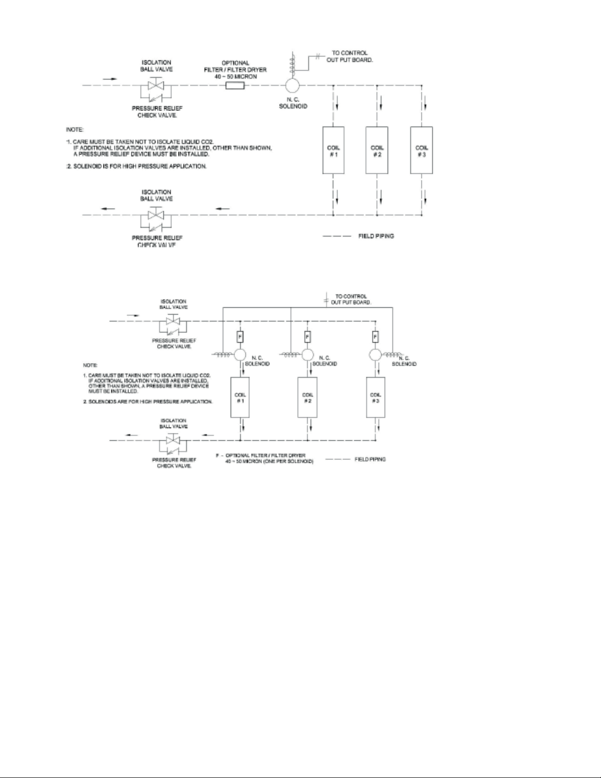
FIGURE 2 Multiple Unit Coolers Controlled By a Single Solenoid ......................................................................................9
FIGURE 3 Multiple Unit Coolers Controlled By Multiple Solenoids.....................................................................................9
FIGURE 4A Air Defrost Wiring Diagrams for Motor Type B...............................................................................................16
FIGURE 4B Air Defrost Wiring Diagram for Motor Type V ................................................................................................16
FIGURE 4C Air Defrost Wiring Diagram for Motor Type D ................................................................................................16
FIGURE 4D Air Defrost Wiring Diagram with Timer - Motor Type B..................................................................................17
FIGURE 4E Air Defrost Wiring Diagram with Timer - Motor Type V……………………. ....................................................17
FIGURE 4F Air Defrost Wiring Diagram with Timer - Motor Type D ..................................................................................17
FIGURE 5A Electric Defrost System with Timer Wiring - Motor Type B ............................................................................18
FIGURE 5B Electric Defrost System with Timer Wiring - Motor Type V ............................................................................18
FIGURE 5C Electric Defrost System with Timer Wiring - Motor Type D............................................................................19
FIGURE 6A Electric Defrost with Timer and Defrost Contactor Wiring - Motor Type B ....................................................19
FIGURE 6B Electric Defrost with Timer and Defrost Contactor Wiring - Motor Type V ....................................................20

4KR Electrical Defrost Unit Coolers (PN E108318_S)
FIGURE 6C Electric Defrost with Timer and Defrost Contactor Wiring - Motor Type D ....................................................20
FIGURE 7A Electric Defrost System Wiring Motor Type B - 3 Phase Heaters .................................................................21
FIGURE 7B Electric Defrost System Wiring Motor Type V - 3 Phase Heaters .................................................................21
FIGURE 7C Electric Defrost System Wiring Motor Type D Motor - 3 Phase Heaters .......................................................22
FIGURE 8A Electric Defrost System Wiring Motor Type B – Multiple Evaporator ............................................................22
FIGURE 8B Electric Defrost System Wiring Motor Type V – Multiple Evaporators ..........................................................23
FIGURE 8C Electric Defrost System Wiring Motor Type D – Multiple Evaporators ..........................................................23
FIGURE 9A H - 3 Pipe Hot Gas with Electric Pan Heat and P - 2 Pipe Kool
Gas with Electric Pan Heat – Motor Type B...................................................................................................24
FIGURE 9B H - 3 Pipe Hot Gas with Electric Pan Heat and P - 2 Pipe Kool
Gas with Electric Pan Heat – Motor Type V ..................................................................................................24
FIGURE 9C H - 3 Pipe Hot Gas with Electric Pan Heat and P - 2 Pipe Kool
Gas with Electric Pan Heat – Motor Type D ..................................................................................................25
FIGURE 10A Model G - 3 Pipe Hot Gas with Gas Pan Heat and K - 2 Pipe Kool
Gas with Gas Pan Heat – Motor Type B......................................................................................................25
FIGURE 10B Models G - 3 Pipe Hot Gas with Gas Pan Heat and K - 2 Pipe Kool
Gas with Gas Pan Heat – Motor Type V .....................................................................................................25
FIGURE 10C Model G - 3 Pipe Hot Gas with Gas Pan Heat and K - 2 Pipe Kool
Gas with Gas Pan Heat – Motor Type D .....................................................................................................26
FIGURE 11A Model H (HGE) – 3 Pipe Hot Gas Defrost with Electric Pan Heat ..............................................................28
FIGURE 11B Model G (HGG) – 3 Pipe Hot Gas Defrost with Hot Gas Pan Heat ............................................................28
FIGURE 12A Model P (KGE) – 2 Pipe Kool Gas Defrost with Electric Pan Heat .............................................................29
FIGURE 12B Model K (KGG) – 2 Pipe Kool Gas Defrost with Gas Pan Defrost ..............................................................29
FIGURE 13 Wiring drawing of Evaporator with system 450 and signal amplier..............................................................31
FIGURE 14 Set Up in Single Compressor Unit - (Compressor Interlock) .........................................................................32
FIGURE 15 DUAL Speed Motor Evaporator Coils - (Motors with Control Harness) .........................................................32
FIGURE 16 Variable Speed Motor Evaporator Coils.........................................................................................................32
FIGURE 17 Defrost Termination Location for Carbon Dioxide (R744) ..............................................................................33
FIGURE 18 Replacement Parts ........................................................................................................................................34

5KR Electrical Defrost Unit Coolers (PN E108318_S)
KR D 2 6 A - 125 T D A A
Unit Type
KR - Compact Series
DOE Application
D - DOE and NR Can
A - Non-Regulated
Number of Fans
4, 6 FPI
Fin Spacing
Type of Defrost
E - Electric Deftost with Electric Pan Heat
A - Air Defrost
G - 3 Pipe Hot Gas with Gas Pan Heat
H - 3 Pipe Hot Gas With Electric Pan Heat
K - 2 Pipe Kool Gas with Gas Pan Heat
P - 2 Pipe Kool Gas with Electric Pan Heat
R - Heat Reclaim
Heater Voltage
B - 115/1/60*
A - 208-230/1/60
K - 208-230/3/60
Motor Voltage
D - Dual Speed EC
A - 208-230/1/60
B - 115/1/60*
S - R-404A
N - Stock Unit***
Refrigerant
B - PSC Motors**
V - Variable Speed EC
Motor Type
BTU/H in Hundreds (00)
B - Glycol / Brine C- CO2
F - R-407F R - R-449A
Q - R-407A T - R-448A
G - Stock Unit****
P - R-507A
*Available on pan heaters for “H” and “P” defrost options only.
** PSC motors are not allowed for DOE/NRCan regulated applications.
DOE/NRCan applications will require Dual Speed orVariable Speed EC fans.
*** N Stock Units are for non-glide or glide refrigerants
**** G Stock Units are for glide refrigerants only
Additional refrigerants are shown
in the TABLE classied as Glide
and Non- Glide for selection of dual
speed or variable speed motors to
meet DOE/NRCan regulations.
Glide Refrigerants Non-glide refrigerants
Dewpoint to bubble TD Dewpoint to bubble TD
R-401A 9.8 R-134a 0
R-401B 9.4 R-22 0
R-407A 10.5 R-402A (HP80) 2.6
R-407F 10.6 R-402B 3.1
R-407H 11.4 R-404A 1
R-409A 14.8 R-408A 0.7
R-409B 13.5 R-410A 0.2
R-417A 7.6 R-502 0
R-422A 7 R-507A 0
R-4220 7 R-513A 0.1
R-438A 10.8
R-448A 10.5
R-449A 9.7
1 RECEIPT OF EQUIPMENT
1.1 INSPECTION
All equipment should be carefully checked for damage or shortages as soon as it is received. Each shipment should
be carefully checked against the bill of lading. If any damage or shortage is evident, a notation must be made on the
delivery receipt before it is signed, and a claim should then be led against the freight carrier.
1.2 LOSS OF GAS HOLDING CHARGE
Each unit cooler is leak tested, evacuated to remove moisture and then shipped with a gas holding charge. Absence
of this charge may indicate a leak has developed in transit. The system should not be charged with refrigerant until it
is veried that there is no leak, or the source of the leak is located.
2 LOCATION RECOMMENDATIONS
For all defrost types (Air, Electric and Hot gas defrost) unit coolers must have proper airow to maintain a uniform
room temperature and have a complete defrost.
These units are draw thru design thus drawing air thru the cooling coil and discharging it into the room via the unit
fans. For best performance it is desirable to arrange the air discharge toward the door of the cooler to minimize
the entrance of warm moist air when the door is open. The unit must be at least 12 inches from the wall to assure
proper air intake.

KR Electrical Defrost Unit Coolers (PN E108318_S) 6
3 UNIT MOUNTING
The unit cooler may be suspended with 3/8” diameter hanger rods or flush mounted to the ceiling
using 5/16” minimum lag screws with flat washers. Rods should be double nutted top and bottom.
The unit must be level in all directions to insure proper drainage of condensate. Suspended units
must have enough clearance above for cleaning the top.
FIGURE 1: UNIT DIMENSIONS
TABLE 1A: ELECTRIC DEFROST UNIT DIMENSIONS AND CONNECTION SIZES
MODEL
NUMBERS
Refrigeration
Connections DIMENSIONS (IN)
LIQ SUCT
L W H
KR*14E-037[ ]{ } 1/2” 5/8” 29.13 15.32 15.90
KR*24E-074[ ]{ } 1/2” 7/8” 47.13 15.32 15.90
KR*34E-111[ ]{ } 1/2” 7/8” 65.13 15.32 15.90
KR*44E-148[ ]{ } 1/2” 1-1/8” 83.13 15.32 15.90
KR*54E-185[ ]{ } 1/2” 1-1/8” 101.1 15.32 15.90
KR*64E-220[ ]{ } 1/2” 1-1/8” 119.1 15.32 15.90
KR*16E-035[ ]{ } 1/2” 5/8” 29.13 15.32 15.90
KR*16E-045[ ]{ } 1/2” 5/8” 29.13 15.32 15.90
KR*26E-090[ ]{ } 1/2” 7/8” 47.13 15.32 15.90
KR*36E-135[ ]{ } 1/2” 7/8” 65.13 15.32 15.90
KR*46E-180[ ]{ } 1/2” 1-1/8” 83.13 15.32 15.90
KR*56E-192[ ]{ } 1/2” 1-1/8” 101.1 15.32 15.90
KR*66E-270[ ]{ } 1/2” 1-1/8” 119.1 15.32 15.90
*Replace with ‘D’ or ‘A’ where ‘D’ units are DOE compliant and ‘A’ are for non-regulated applications.
[ ] Replace with the refrigerant letter code refer to the model nomenclature.
{ } Motor type designation, replace with ‘D’ for Dual Speed or ‘V’ for Variable Speed.

7KR Electrical Defrost Unit Coolers (PN E108318_S)
TABLE 1B: GAS DEFROST UNIT DIMENSIONS AND CONNECTION SIZES
MODEL
NUMBERS
Refrigeration Connections DIMENSIONS (IN)
LIQ SUCT HOT GAS
L W H
KR*14( )-037[ ]{ }
1/2”
5/8” 1/2” 29.13 15.32 15.9
KR*24( )-074[ ]{ }
1/2”
7/8” 1/2” 47.13 15.32 15.9
KR*34( )-111[ ]{ }
1/2”
7/8” 1/2” 65.13 15.32 15.9
KR*44( )-148[ ]{ }
1/2”
1-1/8” 1/2” 83.13 15.32 15.9
KR*54( )-185[ ]{ }
1/2”
1-1/8” 1/2” 101.1 15.32 15.9
KR*64( )-220[ ]{ }
1/2”
1-1/8” 1/2” 119.1 15.32 15.9
KR*16( )-035[ ]{ }
1/2”
5/8” 1/2” 29.13 15.32 15.9
KR*16( )-045[ ]{ }
1/2”
5/8” 1/2” 29.13 15.32 15.9
KR*26( )-090[ ]{ }
1/2”
7/8” 1/2” 47.13 15.32 15.9
KR*36( )-135[ ]{ }
1/2”
7/8” 1/2” 65.13 15.32 15.9
KR*46( )-180[ ]{ }
1/2”
1-1/8” 1/2” 83.13 15.32 15.9
KR*56( )-192[ ]{ }
1/2”
1-1/8” 1/2” 101.1 15.32 15.9
KR*66( )-270[ ]{ }
1/2”
1-1/8” 1/2” 119.1 15.32 15.9
* Replace with ‘D’ or ‘A’ where ‘D’ units are DOE compliant and ‘A’ are for non-regulated applications.
( ) Gas defrost type K, H, G or P. See definition below.
[ ] Replace with the refrigerant letter code refer to the model nomenclature.
{ } Motor type designation, replace with ‘D’ for Dual Speed or ‘V’ for Variable Speed.
TABLE 1C: AIR DEFROST UNIT DIMENSIONS AND CONNECTION SIZES
MODEL
NUMBERS
Refrigeration
Connections DIMENSIONS (IN)
LIQ SUCT
L W H
KRD16A-040[ ]{ } 1/2” 5/8” 29.13 15.32 15.9
KRD16A-060[ ]{ } 1/2” 5/8” 29.13 15.32 15.9
KRD26A-089[ ]{ } 1/2” 7/8” 47.13 15.32 15.9
KRD26A-125[ ]{ } 1/2” 7/8” 47.13 15.32 15.9
KRD36A-134[ ]{ } 1/2” 7/8” 65.13 15.32 15.9
KRD36A-170[ ]{ } 1/2” 1-1/8” 65.13 15.32 15.9
KRD46A-216[ ]{ } 1/2” 1-1/8” 83.13 15.32 15.9
KRD56A-242[ ]{ } 1/2” 1-1/8”
101.13
15.32 15.9
KRD66A-340[ ]{ } 1/2” 1-3/8” 119.13 15.32 15.9
KRD14A-058[ ]{ } 1/2” 5/8” 29.13 15.32 15.9
KRD24A-096[ ]{ } 1/2” 5/8” 47.13 15.32 15.9
KRD24A-117[ ]{ } 1/2” 5/8” 47.13 15.32 15.9
KRD34A-143[ ]{ } 1/2” 5/8” 65.13 15.32 15.9
KRD34A-173[ ]{ } 1/2” 5/8” 65.13 15.32 15.9
KRD44A-191[ ]{ } 1/2” 5/8” 83.13 15.32 15.9
KRD44A-232[ ]{ } 1/2” 5/8” 83.13 15.32 15.9
KRD54A-290[ ]{ } 1/2” 5/8”
101.13
15.32 15.9
KRD64A-348[ ]{ } 1/2” 5/8”
119.13
15.32 15.9
[ ] Replace with the refrigerant letter code refer to the model nomenclature.
{ } Motor type designation, replace with ‘D’ for Dual Speed or ‘V’ for Variable Speed.

KR Electrical Defrost Unit Coolers (PN E108318_S) 8
4 DRAIN LINE
The drain line should be as short and as steeply pitched as possible with a minimum of ¼” drop
per running foot. Any traps in the drain line must be in an ambient above freezing location. If the
temperature sur- rounding the trap or drain line is below freezing (32°F) it must be wrapped with a
drain line heater. Be sure to also wrap the unit drain coupling. Cover the drain line, drain coupling,
and heat tape with insulation. Be sure to follow the manufacturer’s recommendation when installing
the drain line heat tape.
A union at the drain connection in the drain pan is recommended for ease of installation and future
servicing. The union should be located as close to the drain pan as possible. Use two wrenches
when tightening to prevent the drain fitting from twisting and damaging the unit.
Long runs of drain line (i.e., more than a few feet) should be supported by hangers to avoid damage
to the drain pan.
5 REFRIGERATION PIPING
System design must conform to all local and national codes, laws, and regulations applying to the
site of installation. In addition the safety code for mechanical refrigeration (ASME B31.5) should be
followed as a guide for installation and operation practice.
Refrigerant line sizes and piping techniques should be obtained from the ASHRAE Guide or
equivalent reference. Under no circumstances should the refrigerant connection size of the unit be
used as the basis for sizing the lines.
The horizontal suction line should slope away from the unit toward the compressor. Vertical suction
risers may require a trap at the bottom of the riser for proper oil return.
There are two typical methods of defrosting a unit with hot gas. FIGUREs 7A. and 7B (in section 9
“Sequence of Operation”) show typical piping arrangements for 3 pipe hot gas defrost. FIGUREs
8A and 8B show typical piping arrangements for reverse cycle defrost.
For Food Service installations – seal any joint between unit cooler and cooler wall with a sealant
Listed by the National Sanitation Foundation.
Special Instructions for Units Using Carbon Dioxide (R-744)
These unit coolers are intended to utilize carbon dioxide only in a secondary loop or cascade
system. As such, unit installation must comply with the following instructions:
A.
If the refrigeration system is de-energized, venting of the R-744 through the pressure
regulating relief valves on the refrigeration system can occur. In such cases, the
system may need to be recharged with R-744, but in any case, the pressure regulating
relief valve(s) are not to be defeated or capped. The relief setting shall not be altered.
B.
A sufficient number of pressure relief and pressure regulating relief valves may need
to be provided based on the system capacity and located such that no stop valve
is provided between the relief valves and the parts or section of the system being
protected.
To properly protect and control systems using pumped liquid overfeed R-744, the solenoid,
isolation, and pressure relief valves shall be arranged as shown in either FIGURE 2 or 3,
according to the solenoid valve arrangement. To handle the requirements of liquid R-744 high
pressure solenoid valves are to be used.

9KR Electrical Defrost Unit Coolers (PN E108318_S)
FIGURE 2: MULTIPLE UNIT COOLERS CONTROLLED BY A SINGLE SOLENOID
FIGURE 3: MULTIPLE UNIT COOLERS CONTROLLED BY MULTIPLE SOLENOIDS
6 REFRIGERANT DISTRIBUTOR NOZZLES
Distributor nozzles are included using a refrigerant distributor with a changeable nozzle design.
The nozzle(s) are packed in individual plastic envelopes along with a retainer ring and instruction card.
The instruction card provides information on nozzle used based on refrigerant. There may be one, two,
or three envelopes with nozzles located near the distributor.
The nozzles provided with the unit have been selected for design conditions of 10°F T.D. and 95°F liquid
refrigerant at the expansion valve inlet. If the unit will be operated at conditions that are substantially
different from these conditions, it may be necessary to select a different size nozzle. Consult factory for
additional information.
The nozzle must be installed in the distributor or the auxiliary side connector before the expansion
valve is installed. There are nozzle identification numbers stamped on one side of the nozzle. Ensure
the numbers are visible (for identification information) when inserting the nozzle into the distributor.
The nozzle is held in place by a retainer ring that is easily inserted or removed with a pair of needle
nose pliers.
The standard distributor nozzles provided with the units are listed in TABLEs 2A, 2B, and 2C:

KR Electrical Defrost Unit Coolers (PN E108318_S) 10
TABLE 2A: AIR DEFROST MODELS DISTRIBUTOR NOZZLE SELECTIONS
MODELS DISTRIBUTOR NOZZLES1
R-404A R-407A R-448A
KRD16A-060[ ]{ } L - 3/4 L - 1/2 L - 1/2
KRD26A-125[ ]{ } L - 1-1/2 L - 1 L - 1
KRD36A-170[ ]{ } L - 2 L - 1-1/2 L - 1-1/2
KRD46A-216[ ]{ } L - 2-1/2 L - 2 L - 2
KRD56A-242[ ]{ } L - 2-1/2 L - 2 L - 2
KRD66A-340[ ]{ } L - 4 L - 3 L - 3
KRD16A-040[ ]{ } Single Pass Single Pass Single Pass
KRD26A-089[ ]{ } L - 1 L - 3/4 L - 3/4
KRD36A-134[ ]{ } L - 2 L - 1-1/2 L - 1-1/2
KRD14A-058[ ]{ } L - 3/4 L - 1/2 L - 1/2
KRD24A-117[ ]{ } L - 1-1/2 L - 1 L - 1
KRD34A-173[ ]{ } L - 2 L - 1-1/2 L - 1-1/2
KRD44A-232[ ]{ } L - 2-1/2 L - 2 L-2
KRD54A-290[ ]{ } L - 3 L - 2-1/2 L - 2-1/2
KRD64A-348[ ]{ } J - 4 J - 3 J - 3
KRD24A-096[ ]{ } L - 1 L - 3/4 L - 3/4
KRD34A-143[ ]{ } L - 1-1/2 L - 1-1/2 L - 1-1/2
KRD44A-191[ ]{ } L - 2 L - 1-1/2 L - 1-1/2
Distributor nozzle selections are based on +25°F suction temperature, 10°F T.D., and 95°F liquid
temperature.
[ ] Replace with the refrigerant letter code refer to the model nomenclature.
{ } Motor type designation, replace with ‘D’ for Dual Speed or ‘V’ for Variable Speed.
TABLE 2B: ELECTRIC DEFROST MODELS DISTRIBUTOR NOZZLE SELECTIONS
MODELS DISTRIBUTOR NOZZLES1
R-404A R-407A R-448A
KR*14E-037[ ]{ } L - 3/4 L - 1/2 L - 1/2
KR*24E-074[ ]{ } L - 1-1/2 L - 1 L - 1
KR*34E-111[ ]{ } L - 2 L - 1-1/2 L - 1-1/2
KR*44E-148[ ]{ } L - 2 L - 2 L - 2
KR*54E-185[ ]{ } L - 4 L - 2-1/2 L - 2-1/2
KR*64E-220[ ]{ } L - 4 L - 3 L - 3
KR*16E-035[ ]{ } L - 3/4 L - 1/2 L - 1/2
KR*16E-045[ ]{ } L - 3/4 L - 3/4 L - 3/4
KR*26E-090[ ]{ } L - 1-1/2 L - 1-1/2 L - 1-1/2
KR*36E-135[ ]{ } L - 2-1/2 L - 2 L - 2
KR*46E-180[ ]{ } L - 3 L - 2-1/2 L - 2-1/2
KR*56E-192[ ]{ } L - 4 L - 2-1/2 L - 2-1/2
KR*66E-270[ ]{ } L - 6 L - 4 L - 4
Distributor nozzle selections are based on -20°F suction temperature, 10°F T.D., and 95°F liquid
temperature.

11KR Electrical Defrost Unit Coolers (PN E108318_S)
TABLE 2C: GAS DEFROST MODELS DISTRIBUTOR NOZZLE SELECTION
MODELS DISTRIBUTOR NOZZLES1
R-404A R-407A R-448A
KR*14( )-037[ ]{ } L - 3/4 L - 1/2 L - 1/2
KR*24( )-074[ ]{ } L - 1-1/2 L - 1 L - 1
KR*34( )-111[ ]{ } L - 2 L - 1-1/2 L - 1-1/2
KR*44( )-148[ ]{ } L - 2 L - 2 L - 2
KR*54( )-185[ ]{ } L - 4 L - 2-1/2 L - 2-1/2
KR*64( )-220[ ]{ } L - 4 L - 3 L - 3
KR*16( )-035[ ]{ } L - 3/4 L - 1/2 L - 1/2
KR*16( )-045[ ]{ } L - 3/4 L - 3/4 L - 3/4
KR*26( )-090[ ]{ } L - 1-1/2 L - 1-1/2 L - 1-1/2
KR*36( )-135[ ]{ } L - 2-1/2 L - 2 L - 2
KR*46( )-180[ ]{ } L - 3 L - 2-1/2 L - 2-1/2
KR*56( )-192[ ]{ } L - 4 L - 2-1/2 L - 2-1/2
KR*66( )-270[ ]{ } L - 6 L - 4 L - 4
Distributor nozzle selections are based on -20°F suction temperature, 10°F T.D., and 95°F liquid
temperature.
*Replace with ‘D’ or ‘A’ where ‘D’ units are DOE compliant and ‘A’ are for non-regulated applications.
( ) Gas defrost type K, H, G or P. See definition below.
[ ] Replace with the refrigerant letter code refer to the model nomenclature.
{ } Motor type designation, replace with ‘D’ for Dual Speed or ‘V’ for Variable Speed.
NOTE 1: If R-449A is used, use the same Nozzle as mentioned for R-448A
If R-407F is used, use the same Nozzle as mentioned for R-407A
If R-507 is used, use the same Nozzle as mentioned for R-404A

KR Electrical Defrost Unit Coolers (PN E108318_S) 12
7 EXPANSION VALVE
TABLE 7A: RECOMMENDED EXPANSION VALVES FOR AIR DEFROST MODELS
MODELS TXV2
R-404A R-407A R-448A
KRD16A-060[ ]{ } SBFSE-AA-C SBFNE-AA-C SBFDE-AA-C
EGSE-1/2-C EGNE-1/2-C EGDE-1/3-C
KRD26A-125[ ]{ } SBFSE-A-C SBFNE-A-C SBFDE-A-C
EGSE-1-C EGNE-1-C EGDE-1-C
KRD36A-170[ ]{ } SBFSE-B-C SBFNE-A-C SBFDE-A-C
EGSE-1-1/2-C EGNE-1-1/2-C EGDE-1-C
KRD46A-216[ ]{ } SBFSE-B-C SBFNE-A-C SBFDE-A-C
EGSE-1-1/2-C EGNE-1-1/2-C EGDE-1-C
KRD56A-242[ ]{ } SBFSE-B-C SBFNE-B-C SBFDE-B-C
EGSE-2-C EGNE-2-C EGDE-1-1/2-C
KRD66A-340[ ]{ } SBFSE-C-C
EGSE-2-C
SBFNE-B-C
EGNE-3-C
SBFDE-B-C
EGDE-2-1/2-C
KRD16A-040[ ]{ } SBFSE-AA-C SBFNE-AAA-C SBFDE-AAA-C
EGSE-1/4-C EGNE-1/3-C EGDE-1/4-C
KRD26A-089[ ]{ } SBFSE-A-C
EGSE-1-C
SBFNE-AA-C
EGNE-3/4-C
SBFDE-AA-C
EGDE-1/2-C
KRD36A-134[ ]{ } SBFSE-A-C
EGSE-1-C
SBFNE-A-C
EGNE-1-C
SBFDE-A-C
EGDE-1-C
KRD14A-058[ ]{ } SBFSE-AA-C SBFNE-AA-C SBFDE-AA-C
EGSE-1/2-C EGNE-1/2-C EGDE-1/3-C
KRD24A-117[ ]{ } SBFSE-A-C SBFNE-A-C SBFDE-A-C
EGSE-1-C EGNE-1-C EGDE-1/2-C
KRD34A-173[ ]{ } SBFSE-B-C SBFNE-A-C SBFDE-A-C
EGSE-1-1/2-C EGNE-1-1/2-C EGDE-1-C
KRD44A-232[ ]{ } SBFSE-B-C SBFNE-B-C SBFDE-B-C
EGSE-2-C EGNE-2-C EGDE-1-1/2-C
KRD54A-290[ ]{ } SBFSE-C-C
EGSE-2-C
SBFNE-B-C SBFDE-B-C
EGNE-3-C EGDE-1-1/2-C
KRD64A-348[ ]{ } SBFSE-C-C
EGSE-2-C
SBFNE-B-C
EGNE-3-C
SBFDE-B-C
EGDE-2-1/2-C
KRD24A-096[ ]{ } SBFSE-A-C
EGSE-1-C
SBFNE-AA-C
EGNE-3/4-C
SBFDE-AA-C
EGDE-1/2-C
KRD34A-143[ ]{ } SBFSE-A-C
EGSE-1-C
SBFNE-A-C
EGNE-1-C
SBFDE-A-C
EGDE-1-C
KRD44A-191[ ]{ } SBFSE-B-C SBFNE-A-C SBFDE-A-C
EGSE-1-1/2-C EGNE-1-1/2-C EGDE-1-C
TXV selections are based on +25°F suction temperature, 10°F T.D., and 95°F liquid temperature,
105°F Condensing temperature and high side pressure drop of 10 PSIG.

13KR Electrical Defrost Unit Coolers (PN E108318_S)
TABLE 7B: RECOMMENDED EXPANSION VALVES FOR ELECTRIC DEFROST MODELS
MODELS TXV
R404A R407A R448A
KR*14E-037[ ]{ } SBFSE-AA-Z
EGSE-1/4-Z
SBFNE-AA-Z
EGNE-1/2-Z
SBFDE-AAA-Z
EGDE-1/4-Z
KR*24E-074[ ]{ } SBFSE-A-Z
EGSE-1-Z
SBFNE-A-Z
EGNE-1-Z
SBFDE-AA-Z
EGDE-1/2-Z
KR*34E-111[ ]{ } SBFSE-A-Z
EGSE-1-Z
SBFNE-A-Z
EGNE-1-1/2-Z
SBFDE-A-Z
EGDE-1-Z
KR*44E-148[ ]{ } SBFSE-B-Z
EGSE-1-1/2-Z
SBFNE-B-Z
EGNE-2-Z
SBFDE-A-Z
EGDE-1-Z
KR*54E-185[ ]{ } SBFSE-B-Z
EGSE-2-Z
SBFNE-B-Z
EGNE-2-Z
SBFDE-A-Z
EGDE-1-Z
KR*64E-220[ ]{ } SBFSE-C-Z
EGSE-2-Z
SBFNE-B-Z
EGNE-3-Z
SBFDE-B-Z
EGDE-1 1/2-Z
KR*16E-035[ ]{ } SBFSE-AA-Z
EGSE-1/4-Z
SBFNE-AA-Z
EGNE-1/2-Z
SBFDE-AAA-Z
EGDE-1/4-Z
KR*16E-045[ ]{ } SBFSE-AA-Z
EGSE-1/2-Z
SBFNE-AA-Z
EGNE-3/4-Z
SBFDE-AA-Z
EGDE-1/3-Z
KR*26E-090[ ]{ } SBFSE-A-Z
EGSE-1-Z
SBFNE-A-Z
EGNE-1-Z
SBFDE-A-Z
EGDE-1/2-Z
KR*36E-135[ ]{ } SBFSE-B-Z
EGSE-1 -1/2-Z
SBFNE-B-Z
EGNE-2-Z
SBFDE-A-Z
EGDE-1-Z
KR*46E-180[ ]{ } SBFSE-B-Z
EGSE-2-Z
SBFNE-B-Z
EGNE-2-Z
SBFDE-A-Z
EGDE-1-Z
KR*56E-192[ ]{ } SBFSE-B-Z
EGSE-2-Z
SBFNE-B-Z
EGNE-2-Z
SBFDE-B-Z
EGDE-1 -1/2-Z
KR*66E-270[ ]{ } SBFSE-C-Z
EGSE-2-Z
SBFNE-C-Z
EGNE-3-Z
SBFDE-B-Z
EGDE-2-1/2-Z
TXV selections are based on +25°F suction temperature, 10°F T.D., and 95°F liquid temperature,
105°F Condensing temperature and high side pressure drop of 10 PSIG.
NOTE 2: For R-507, replace the second ‘S’ with ‘P’ in R-404-A TXV. For example,
SBFSE-B-C (R- 404A)
becomes SBFPE-B-C and EGSE-1-1/2-C becomes EGPE-1-1/2-C (R-507)
For R-449A, use the same TXV as R-448A
For R-407F, use the same TXV as R-407A

KR Electrical Defrost Unit Coolers (PN E108318_S) 14
TABLE 7C: RECOMMENDED EXPANSION VALVES FOR GAS DEFROST MODELS
MODELS TXV
R404A R407A R448A
KR*14( )-037[ ]{ } SBFSE-AA-Z
EGSE-1/4-Z
SBFNE-AA-Z
EGNE-1/2-Z
SBFDE-AAA-Z
EGDE-1/4-Z
KR*24( )-074[ ]{ } SBFSE-A-Z
EGSE-1-Z
SBFNE-A-Z
EGNE-1-Z
SBFDE-AA-Z
EGDE-1/2-Z
KR*34( )-111[ ]{ } SBFSE-A-Z
EGSE-1-Z
SBFNE-A-Z
EGNE-1-1/2-Z
SBFDE-A-Z
EGDE-1-Z
KR*44( )-148[ ]{ } SBFSE-B-Z
EGSE-1-1/2-Z
SBFNE-B-Z
EGNE-2-Z
SBFDE-A-Z
EGDE-1-Z
KR*54( )-185[ ]{ } SBFSE-B-Z
EGSE-2-Z
SBFNE-B-Z
EGNE-2-Z
SBFDE-A-Z
EGDE-1-Z
KR*64( )-220[ ]{ } SBFSE-C-Z
EGSE-2-Z
SBFNE-B-Z
EGNE-3-Z
SBFDE-B-Z
EGDE-1 1/2-Z
KR*16( )-035[ ]{ } SBFSE-AA-Z
EGSE-1/4-Z
SBFNE-AA-Z
EGNE-1/2-Z
SBFDE-AAA-Z
EGDE-1/4-Z
KR*16( )-045[ ]{ } SBFSE-AA-Z
EGSE-1/2-Z
SBFNE-AA-Z
EGNE-3/4-Z
SBFDE-AA-Z
EGDE-1/3-Z
KR*26( )-090[ ]{ } SBFSE-A-Z
EGSE-1-Z
SBFNE-A-Z
EGNE-1-Z
SBFDE-A-Z
EGDE-1/2-Z
KR*36( )-135[ ]{ } SBFSE-B-Z
EGSE-1 -1/2-Z
SBFNE-B-Z
EGNE-2-Z
SBFDE-A-Z
EGDE-1-Z
KR*46( )-180[ ]{ } SBFSE-B-Z
EGSE-2-Z
SBFNE-B-Z
EGNE-2-Z
SBFDE-A-Z
EGDE-1-Z
KR*56( )-192[ ]{ } SBFSE-B-Z
EGSE-2-Z
SBFNE-B-Z
EGNE-2-Z
SBFDE-B-Z
EGDE-1 -1/2-Z
KR*66( )-270[ ]{ } SBFSE-C-Z
EGSE-2-Z
SBFNE-C-Z
EGNE-3-Z
SBFDE-B-Z
EGDE-2-1/2-Z
TXV selections are based on +25°F suction temperature, 10°F T.D., and 95°F liquid temperature,
105°F Condensing temperature and high side pressure drop of 10PSIG.
*Replace with ‘D’ or ‘A’ where ‘D’ units are DOE compliant and ‘A’ are for Non-Regulated applications
[ ] Replace with the refrigerant letter code refer to the model nomenclature.
{ } Motor type designation, replace with ‘D’ for Dual Speed or ‘V’ for Variable Speed.
NOTE 2: For R-507, replace the second ‘S’ with ’P’ in R-404A TXV. For example, SBFSE-B-C (R-404A)
becomes SBFPE-B-C and EGSE-1-1/2-C becomes EGPE-1-1/2-C (R-507)
For R-449A, use the same TXV as R-448A
For R-407F, use the same TXV as R-407A
Before installing the unit, install the expansion valve and connect the equalizer tube (not required
on single fan units).
Expansion valves are adjusted at the factory prior to shipment. The setting will be okay for many
applications, but in some applications, adjustments may need to be made.
It is important that the operation of the expansion valve be checked out after the system has balanced out
at the desired room temperature. If the coil is being starved, it is necessary to reduce the superheat setting
of the valve by turning the adjusting stem counterclockwise. If the superheat is too low, it is necessary to
increase the superheat setting of the valve by turning the adjusting stem clockwise. It is recommended that
for a 10°F to 12°F T.D. system, the valve should be adjusted to maintain 5°F to 6°F superheat.

15KR Electrical Defrost Unit Coolers (PN E108318_S)
To prevent overshooting the desired setting, only one turn of the stem should be made at a time.
As much as 30 minutes may be required for the new balance to take place after an adjustment is made.
Always tighten the adjusting stem packing nut and replace the seal cap tightly after the adjustment is
complete.
8 WIRING
WARNING: All power supplied to the unit must be shut off before opening any
compartments, cleaning, or performing maintenance.
The electrical data for the unit is marked on the unit nameplate. Field wiring should comply with NFPA
70®(NEC) and local codes. The field wiring compartment is constructed as part of the unit cooler
enclosure. Wiring connections are made at the terminal block provided inside the unit on the end
opposite the refrigerant connections. The unit must be grounded. Refer to TABLE 8 and 9 for unit amps.
TABLE 8: MOTOR AND DEFROST ELECTRICAL INFORMATION – ELECTRIC DEFROST
No. of
Fans
Total Full Load Amps E(EDL) Heaters Amp
PSC Motor (Type B) EC Motor (Type V&D)
E(EDL)
Heaters
Watt
230/1/60 230/3/60
E(EDL)
Heaters
Watt
460/1/60
115/1/60 230/1/60 115/1/60 230/1/60
1
0.7 0.3 0.9 0.6 1000 4.3 2.9 64 2.2
2
1.4 0.6 1.8 1.2 2000 8.7 5.8 128 4.4
3
2.1 0.9 2.7 1.8 3000 13 8.7 192 6.6
4
2.8 1.2 3.6 2.4 4000 17.4 11.6 256 8.8
5
3.5 1.5 4.5
3
5000 21.7 14.5 320 11
6
4.2 1.8 5.4 3.6 6000 26.1 17.4 384 13.2
Note: Air Defrost models have the same motor amps as the ones shown above.
TABLE 9: MOTOR AND DEFROST ELECTRICAL INFORMATION – HOT GAS DEFROST
No.
of
Fans
Total Full Load Amps Defrost Heaters Amps
PSC Motor EC Motor
Heaters
Watts 115/1/60 230/1/60
115/1/60 230/1/60 115/1/60 230/1/60
1
0.7 0.3 0.9 0.6 300 2.6 1.3
2
1.4 0.6 1.8 1.2 600 5.2 2.6
3
2.1 0.9 2.7 1.8 800
7
3.5
4
2.8 1.2 3.6 2.4 1000 8.7 4.3
5
3.5 1.5 4.5 3.0 1100 9.6 4.8
6
4.2 1.8 5.4 3.6 1400 12.2 6.1

KR Electrical Defrost Unit Coolers (PN E108318_S) 16
8.1
AIR DEFROST MODELS WIRING DIAGRAMS
FIGURE 4A: AIR DEFROST WIRING DIAGRAM FOR MOTOR TYPE B
FIGURE 4B: AIR DEFROST WIRING DIAGRAM FOR MOTOR TYPE V
FIGURE 4C: AIR DEFROST WIRING DIAGRAM FOR MOTOR TYPE D

17KR Electrical Defrost Unit Coolers (PN E108318_S)
FIGURE 4D: AIR DEFROST WIRING DIAGRAM WITH TIMER - MOTOR TYPE B
FIGURE 4E: AIR DEFROST WIRING DIAGRAM WITH TIMER - MOTOR TYPE V
FIGURE 4F: AIR DEFROST WIRING DIAGRAM WITH TIMER - MOTOR TYPE D

KR Electrical Defrost Unit Coolers (PN E108318_S) 18
8.2
ELECTRIC DEFROST MODELS WIRING DIAGRAMS
FIGURE 5A: ELECTRIC DEFROST SYSTEM WITH TIMER WIRING - MOTOR TYPE B
FIGURE 5B: ELECTRIC DEFROST SYSTEM WITH TIMER WIRING - MOTOR TYPE V

19KR Electrical Defrost Unit Coolers (PN E108318_S)
FIGURE 5C: ELECTRIC DEFROST SYSTEM WITH TIMER WIRING - MOTOR TYPE D
FIGURE 6A: ELECTRIC DEFROST WITH TIMER AND DEFROST CONTACTOR
WIRING - MOTOR TYPE B
Table of contents
Other KRACK Accessories manuals
Popular Accessories manuals by other brands

View
View Sky Sensor installation guide

Banner
Banner World-Beam QS18 Series instruction manual

Sterilize+
Sterilize+ UV-C SANITIZING TOWER manual

Brita
Brita Clorox Clean-Up Cleaner with Bleach 35417 manual

PCB Piezotronics
PCB Piezotronics Y206C Installation and operating manual

Maxim Integrated
Maxim Integrated MAXREFDES220 manual

PCB Piezotronics
PCB Piezotronics 356B11 Installation and operating manual

ekwb
ekwb EK-FB ASUS Maximus XI EXTREME installation manual

Euroflex
Euroflex MB-flex S aluminium Quick installation guide

Hornbach
Hornbach 6145050 Installation and user manual

Soundsmith
Soundsmith ZEPHYR MIMC Owner's manual and technical documentation

turck
turck RU D UPN8X2 Series quick start guide