www.galltec-mela.de
Galltec+Mela
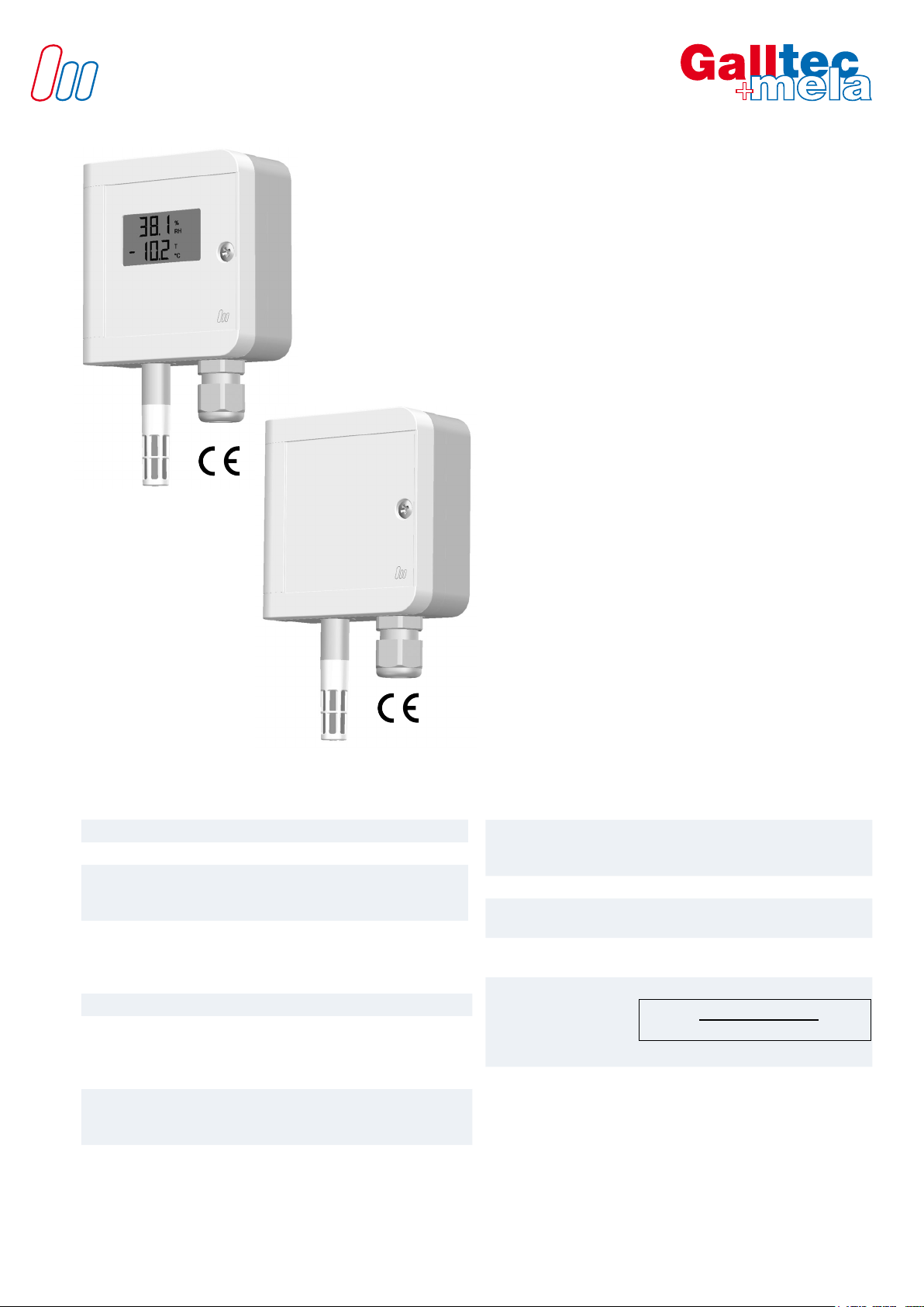
D Series_DW
page 10 of 10
This information is based on current knowledge and is intended to provide details of our products and their possible applications. It
does not, therefore, act as a guarantee of specic properties of the products described or of their suitability for a particular applica-
tion. It is our experience that the equipment may be used across a broad spectrum of applications under the most varied conditions
and loads. We cannot appraise every individual case. Purchasers and/or users are responsible for checking the equipment for
suitability for any particular application. Any existing industrial rights of protection must be observed. The quality of our products is
guaranteed under our General Conditions of Sale. Data sheet DW_e. Issue: June 2018. Subject to modications.
Userinstructions
Dew formation Dew formation and splashes do not damage the sensor, although measurement
readings are corrupted until all moisture on and around the sensing element has
dried up completely.
Cleaning of
lters and
protective baskets
If necessary, soiled lters can be screwed off and rinsed carefully. Bear in mind the
sensors wil not measure accurately until lters are completely dry. Please do not
touch the highly sensitive humidity sensing element. Please ensure that the tempe-
rature sensing element does not touch the sensitive surface of the humidity sensing
element.
Cleaning of
the capacitive
humidity sensing element
Loose dust can be carefully cleaned off the humidity sensing element using distilled
water or by blowing the dust carefully off. Please do not touch the highly sensitive
humidity sensing element. Please ensure that the temperature sensing element does
not touch the sensitive surface of the humidity sensing element.
Damaging inuences Depending on type and concentration, agents that are corrosive and contain solvents,
can result in faulty measurements and can cause the sensor to break down.
Substances deposited on the sensor (e. g. resin aerosols, lacuer aerosols, smoke
deposits etc.) are damaging as they eventually form a water-repellent lm.
Position Install the sensor at a place where characteristic levels of humidity occur. The measu-
ring chamber should be located in streaming air. Avoid installation next to heaters,
doors or on outer walls. Avoid places exposed to the sun.
Do not position the sensor where ingress of water could occur.
To close the housing securely turn screw until dead stop.
We recommend that you lay the connection lines in a loop so that any water that
may be present can run off.
Not reaching the given minimum air speed can lead to measurement errors.
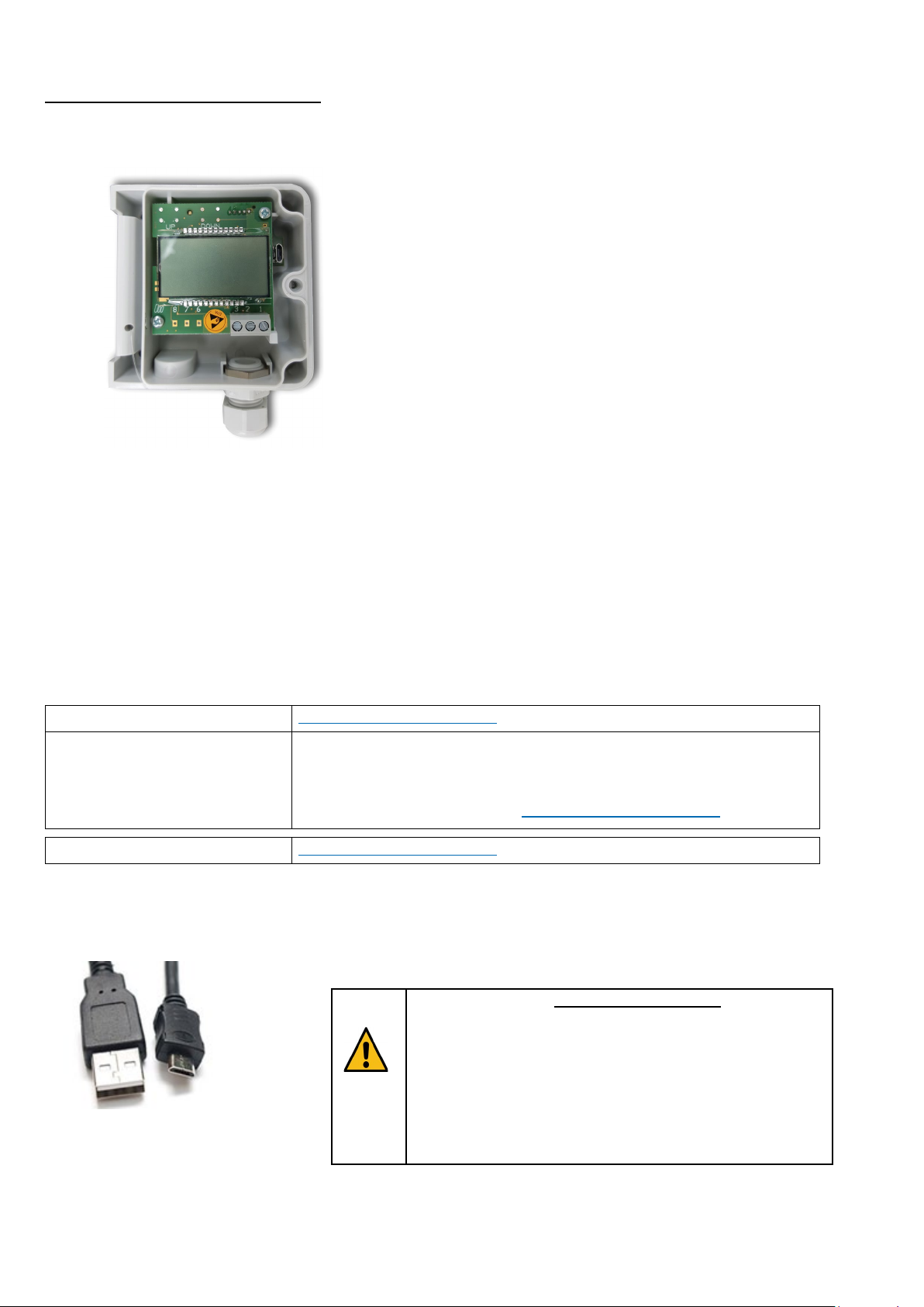
Connection The electrical connection must be carried out by qualied personnel only.
The sensor contains sensitive electrical components. When opening the housing,
make sure you comply with the electrostatic discharge precautions (ESD).
Please pay attention to the ohmic resistance according to the operating voltage (see
diagram on page 2) when using sensors with a current output. Else measurement
errors may occur.
Lines to and from the sensor must not be installed parallel to strong electromagnetical
elds.
If there is any chance of an electrical surge, please install surge protection devices.
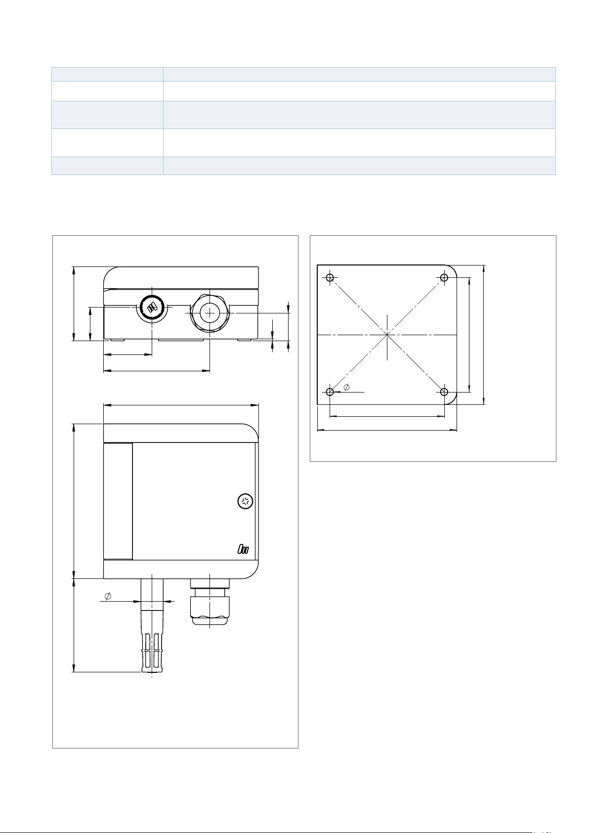
Mountinginstructions