KRAMBLE INDUSTRIES Swing Auger Movers User manual

Remote Control Swing Auger Mover
Installation and Operating Manual

Revision 4 Endgate and Hoist Page | 2
Table of Contents
Installation Instructions ............................................................................................................................... 2
Mechanical Installation ............................................................................................................................ 2
Electric Cable Installation ......................................................................................................................... 5
General Operation ........................................................................................................................................ 8
Control Console ........................................................................................................................................ 8
Auxiliary Output (option) ......................................................................................................................... 8
Transmitter/Receiver Matching .............................................................................................................. 9
Channel Select Settings .......................................................................................................................... 10
Transmitter ............................................................................................................................................. 10
Transport Winch (option)....................................................................................................................... 11
Specifications .............................................................................................................................................. 12
FCC .............................................................................................................................................................. 13
Industry Canada ......................................................................................................................................... 13
Limited Warranty ....................................................................................................................................... 14
Figure 1 Mechanical Assembly .................................................................................................................... 2
Figure 2 Mounting Position ......................................................................................................................... 3
Figure 3 Jack Installation ............................................................................................................................. 4
Figure 4 Cable Diagram ............................................................................................................................... 5
Figure 5 Underside of Case Diagram ........................................................................................................... 6
Figure 6 Console Diagram ........................................................................................................................... 7
Figure 6 Receiver Matching ......................................................................................................................... 9

Revision 4 Swing Auger Mover Page | 2
Kramble Industries Inc. is not responsible or liable for indirect, special, or consequential damages arising out of or in connection
with the use or performance of the product or other damage with respect to any economic loss, loss of property, loss of revenue
or profit, or costs of removal, installation, or reinstallation.
Installation Instructions
Mechanical Installation
The Swing Auger Mover is designed to clamp directly onto the swing auger tube at the lowest
point. Using the six 7/16 x 2-1/2” bolts provided, tighten the clamp around the tube such that
the main beam is horizontal when the hopper is on level ground and the auger is at its normal
working height. Clamps are available for 10”, 12”, 13”, 14” and 16” Augers.
Figure 1 Mechanical Assembly

Revision 4 Swing Auger Mover Page | 3
Kramble Industries Inc. is not responsible or liable for indirect, special, or consequential damages arising out of or in connection
with the use or performance of the product or other damage with respect to any economic loss, loss of property, loss of revenue
or profit, or costs of removal, installation, or reinstallation.
Figure 2 Mounting Position
There is a grease nipple located on each axle sleeve. Grease before first operation and thereafter,
thereafter, as needed.
Clamp the Swing Auger Mover Drive at the
lowest point possible on the swing auger
tube so that, on level ground, the Main
Beam is level without extending the jack,
and all of the weight is off the inside
wheels of hopper.

Revision 4 Swing Auger Mover Page | 4
Kramble Industries Inc. is not responsible or liable for indirect, special, or consequential damages arising out of or in connection
with the use or performance of the product or other damage with respect to any economic loss, loss of property, loss of revenue
or profit, or costs of removal, installation, or reinstallation.
Figure 3 Jack Installation
Jack
Bolts
Grease
Nipple

Revision 4 Swing Auger Mover Page | 5
Kramble Industries Inc. is not responsible or liable for indirect, special, or consequential damages arising out of or in connection
with the use or performance of the product or other damage with respect to any economic loss, loss of property, loss of revenue
or profit, or costs of removal, installation, or reinstallation.
Electric Cable Installation
The Swing Auger Mover is provided with pre-cut wire lengths with color-coded connectors
attached.
Cable Schedule:
Tractor Power Cable - 12’ c/w Red/Black PowerPole Connector.
Console Power Cable - 9’ c/w Red/Black PowerPole Connector
Console/Swing Cable - 6’ c/w Black/Black PowerPole Connector
Console/Winch Cable - 14’ c/w ¼” Ring Terminals
Figure 4 Cable Diagram
The polarity must be correct as follows: +12v on the RED STRIPE wire on the POWER CABLES
FROM THE TRACTOR TO THE CONTROL CONSOLE. The RED /BLACK connector shells MUST
MATCH.
WARNING: DO NOT ATTEMPT TO POWER THE CONSOLE OR DRIVE FROM A BATTERY
CHARGER ALONE AS DAMAGE MAY OCCUR. CONNECT TO A PROPERLY MAINTAINED BATTERY
SYSTEM ONLY.

Revision 4 Swing Auger Mover Page | 6
Kramble Industries Inc. is not responsible or liable for indirect, special, or consequential damages arising out of or in connection
with the use or performance of the product or other damage with respect to any economic loss, loss of property, loss of revenue
or profit, or costs of removal, installation, or reinstallation.
Figure 5 Underside of Case Diagram
Connect the 6’ Console/Swing cable, the Console/Winch cable and the 9’ Console/Power cable
to the terminal block on the underside of the Swing Auger Mover Console For the
Console/Winch cable, connect the Blue wire to Winch terminal A and the Yellow wire to Winch
terminal B. Attach the Winch power wires to the +/- 12V power terminals of the Swing Auger
Mover Console, then fasten all cables to the terminals using the lock washers and ¼”-20 nuts
supplied. Attach the Swing Auger Mover Console at a convenient height on the swing auger
tube using the gear type clamps provided through the console holes. Connect the free end of
the Console/Winch cable to the matching connector on the Winch.
Install the 12’ Tractor Power cable onto the 12V tractor battery terminals, using the pre-
crimped 3/8” ring terminals and the 80A self-resetting fuse assembly included. The fuse
assembly must be installed between the positive battery terminal and the Red conductor of the
12’ Tractor Power cable to protect against the possibility of a short circuit. Be sure to install the
fuse assembly observing the correct polarity as indicated by the engraved “BATT” label on the
aluminum fuse bar.
Connect the 6’ Console/Swing cable to the Swing Auger Mover wheel assembly motor cable.
The polarity for the Swing A/B terminals will reverse during normal operation. If the Wheel
Drive is running in the wrong direction when operated, exchange the Swing A and B wires.
Similarly, the Winch directions can be reversed by exchanging its A and B wires.
Connect the 9’ Console/Power cable to the 12’ Tractor Power cable.
Secure cables to the swing auger tube using the supplied gear type clamps as shown.
WARNING: DO NOT CONNECT THE TRACTOR POWER CABLES TO THE CONTROL CONSOLE
OUTPUT TERMINALS AS AN ELECTRICAL SHORT AND SERIOUS DAMAGE OR INJURY COULD
RESULT!

Revision 4 Swing Auger Mover Page | 7
Kramble Industries Inc. is not responsible or liable for indirect, special, or consequential damages arising out of or in connection
with the use or performance of the product or other damage with respect to any economic loss, loss of property, loss of revenue
or profit, or costs of removal, installation, or reinstallation.
Figure 6 Console Diagram
Indicator LEDs Power (red) –
Power On/System Ready
Receive/Learn (yellow) – Data
receiving from
transmitter/system in learn
mode
Master Power PUSH to operate
Indicator LEDs Output
(Green) – Power to motor /
fault states indicator (slow
blink for low battery and
fast blink for high
temperature
Learn Control – Hold
during powerup to
match to a transmitter
Swing Motor Direction
Control
Momentary – Hold to
Operate
Auxiliary Output – Press
both buttons
simultaneously to toggle
+12V Auxiliary output
Auxiliary +12V output
(optional)
Entry access for Power and Drive
Gear Type Clamp location
Transport Winch Direction
Control Momentary –
Hold to operate
Gear Type Clamp location

Revision 4 Swing Auger Mover Page | 8
Kramble Industries Inc. is not responsible or liable for indirect, special, or consequential damages arising out of or in connection
with the use or performance of the product or other damage with respect to any economic loss, loss of property, loss of revenue
or profit, or costs of removal, installation, or reinstallation.
General Operation
Control Console
The Control Console contains the radio Receiver and power control circuits. The Control
Console is equipped with a Master Power On/Off switch on the outside of the case. When the
switch is ON, the Red LED should be lit indicating normal operation. Press and release to turn
On and Off.
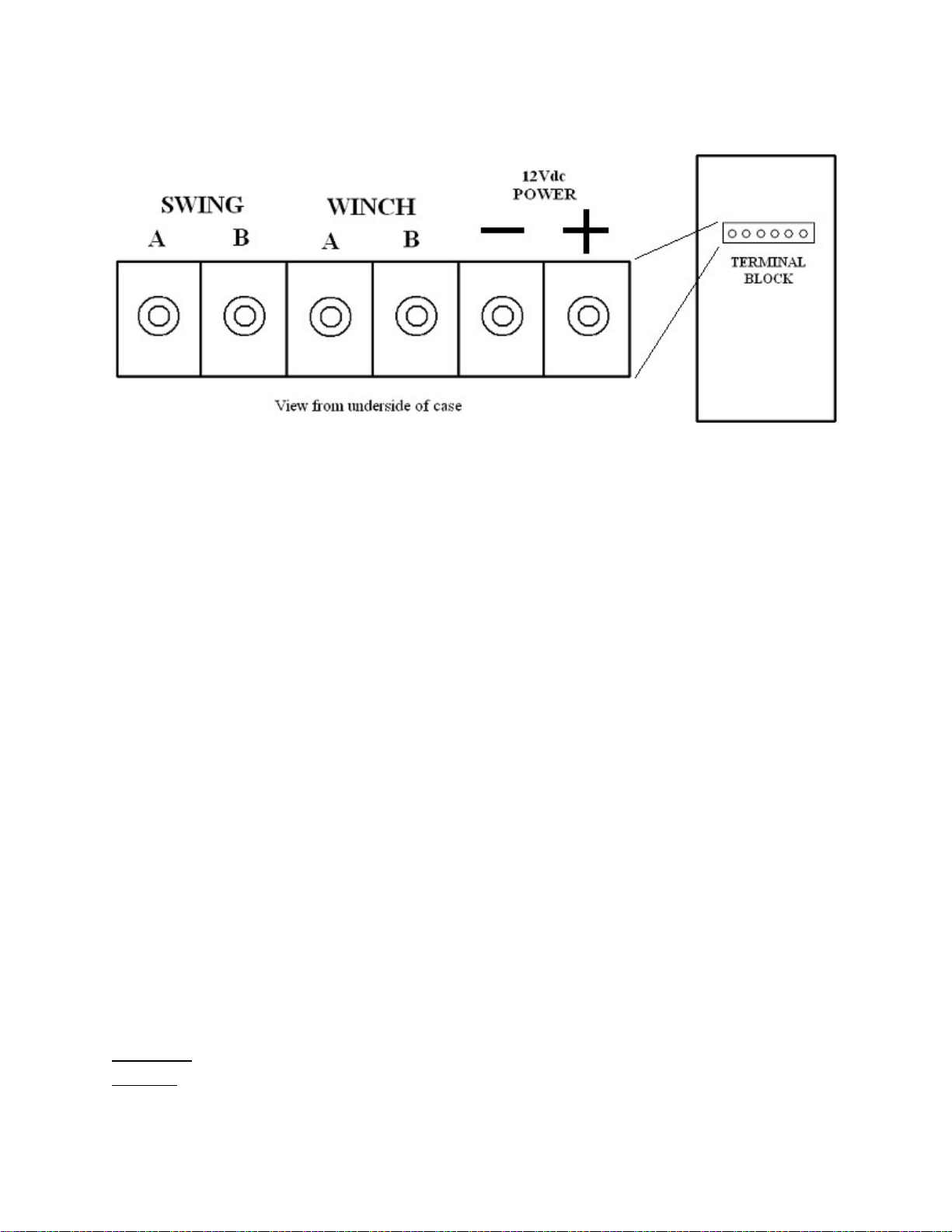
Each of the Swing Auger Drive and Winch may be operated independently from the Control
Console by pressing the desired momentary switch. The Green “Output” LED will come on and
the selected device will operate.
The Control Console also has built-in fault status indicators. For ease of troubleshooting, if a
“low voltage” status occurs to the Control Console, the green Fault States Indicator will blink
approximately twice per second. Check all connections to ensure they are clean and tight. Make
sure that the tractor battery is fully charged, and the engine is running. If a “control circuit high
temperature” status occurs the green Fault States Indicator will flash rapidly, blinking
approximately four times per second. Allow the unit to cool before resuming operation.
Each Swing Auger Mover has its own RF receiver located in the control console, which is
channel selectable to operate in multi-component environments e.g. remote control trailer
chutes on Channels 1 & 2, and the Swing Auger Mover on Channel 3. The user can select the
desired channel using the 2-position dip-switch. All Swing Auger Movers are set to Channel 1 at
the factory.
Auxiliary Output (option)
The Control Console Auxiliary Output provides a remote control power output capable of
delivering 10A (120 watts). This feature is intended for the operation of a remote control light
for illuminating the work area when approaching at night, or for operation of a camera or other
device. The output can be activated and deactivated from the transmitter by pressing the
centre button on the RF transmitter (marked AUX), or from the Control Console by pressing the
two “Aux” control buttons on the face of the Control Console simultaneously. The auxiliary
output is protected by a thermal fuse that automatically resets when cooled. The auxiliary
output is automatically shut off when the fuse trips to prevent a repeating cycle of the fuse
tripping and resetting and must be reactivated using the transmitter or Console controls.

Revision 4 Swing Auger Mover Page | 9
Kramble Industries Inc. is not responsible or liable for indirect, special, or consequential damages arising out of or in connection
with the use or performance of the product or other damage with respect to any economic loss, loss of property, loss of revenue
or profit, or costs of removal, installation, or reinstallation.
Transmitter/Receiver Matching
To match the transmitter to the receiver console:
Shut off power
Hold the learn button (swing left)
Turn power on while still holding the learn button; the receiver light learn light should
come on
Release learn button
Press any button on remote to have the receiver learn that remote.
Your receiver can learn up to 8 remotes. If you add a ninth remote the first one will be
To erase all stored security codes, turn the receiver power ON while holding the LEARN button,
and continue holding the button until the Receive/LEARN light begins to rapidly flash. Release
the button, and the light will flash more slowly for three seconds, then turn off to indicate that
the erase operation has succeeded. If the LEARN button is pressed while the Receive/LEARN
light is slowly flashing, the erase operation is aborted and the receiver retains the stored
transmitter security codes.
The Receiver is equipped with a two-position switch to enable or disable the learn and erase
functions. To enable or disable a function, open the case and locate the switch as illustrated
below. The switches and their positions are labeled on the circuit board. Factory default
systems are set by default so that the Learn function is Enabled and the Erase function is
Disabled.
Figure 7 Receiver Matching

Revision 4 Swing Auger Mover Page | 10
Kramble Industries Inc. is not responsible or liable for indirect, special, or consequential damages arising out of or in connection
with the use or performance of the product or other damage with respect to any economic loss, loss of property, loss of revenue
or profit, or costs of removal, installation, or reinstallation.
Channel Select Settings
The Swing Auger Mover comes with a 2-position DIP Switch to match the Drive to the desired
transmitter channel. In multi-component environments, be sure that each drive is set to a
different channel so that devices do not operate simultaneously. Select the switch settings as
follows:
Switch 1 Switch 2
Channel 1 OFF OFF
Channel 2 ON OFF
Channel 3 OFF ON
Channel 4 ON ON
The Swing Auger Mover and Winch can be operated using the Transmitter, or alternatively, by
operating the UP/DOWN momentary switches on the Control Console. Whenever the Swing
Auger Mover drive or Winch is operated by remote control the Yellow “Receive Data” LED will
be lit along with the Green LED indicating power output to the drive.
The Swing Auger Mover has two automatically resetting fuses. Fuse F1 (1 Amp) inside the
control console is intended to protect the RF receiver and data circuitry, and Fuse F2 (80 Amp)
at the battery is intended to protect against a short circuit in the cables. These fuses will
automatically reset when cooled.
The Control Console power switch should be turned Off when not in use to prevent undesired
operation.
Transmitter
The Transmitter is powered by a 9V battery which, when installed, should light the red "power"
light when a switch is pressed. If the battery does not exceed 7 volts the Power light will not
come On, indicating battery replacement is required.
The Transmitter is also equipped with an Off/Standby switch to prevent accidental operation. In
the OFF position the transmitter Red LED will not light and the transmitter will not activate
even when a function button is pressed. To operate, slide the switch to STANDBY. The
transmitter remains off until a function button is pressed, at which time the Red LED will light
and the transmitter will emit signal. No battery power is used when simply in Standby mode
with no function buttons pressed.
Each transmitter contains a unique identifying security code that is transmitted to the receiver
during RF operation. Up to eight Transmitters can "talk" to the same Receiver as long as the
receiver has learned the transmitters’ security codes. See page 9 for Security Code Matching
Instructions.
To access the battery, remove the 4 screws in the back of the Transmitter case and open the
case.

Revision 4 Swing Auger Mover Page | 11
Kramble Industries Inc. is not responsible or liable for indirect, special, or consequential damages arising out of or in connection
with the use or performance of the product or other damage with respect to any economic loss, loss of property, loss of revenue
or profit, or costs of removal, installation, or reinstallation.
Transport Winch (option)
The Transport Winch is provided for ease of lifting of the swing auger and hopper to and from
the transport position. This electric winch operates on 12VDC power provided by the tractor
battery and is controlled by manual switch on the Console, or by remote control.
The customer can decide the optimum mounting location and utilization for each application.
The electric winch may be employed to replace the existing hand-crank winch or alternatively,
to operate in addition to the hand-crank winch.
To install the winch on the mounting plate provided, the customer should unwind the cable to
get access to the two mounting holes, which are located underneath the drum. Unwind the
cable until you have enough space to drop a bolt through each hole then screw the nuts on
from the bottom.
The Transport Winch option uses a 6000lb 12VDC electric winch.
It is imperative to follow all winching instructions as contained in the Owner’s Manual.
See wiring diagram provided for proper connections.
Think Safety!
STAND CLEAR WHILE OPERATING AND ALWAYS USE SAFETY CHAIN
WHEN RAISED

Revision 4 Swing Auger Mover Page | 12
Kramble Industries Inc. is not responsible or liable for indirect, special, or consequential damages arising out of or in connection
with the use or performance of the product or other damage with respect to any economic loss, loss of property, loss of revenue
or profit, or costs of removal, installation, or reinstallation.
Specifications
Transmitter:
Power: 9 Volt DC Battery
Frequency: 916 MHz
Modulation: FM
Indicators: Power/Transmit Red LED
Case Size: 2.5” x 4.2” x .8”
Weight: .25lb
Range: 300’ + (depending on environment)
Antenna: 1.3” Fixed Mini Tuned
Security Code: Unique in each Transmitter
Safety: Off / Standby Slide Switch
Functions: 2 to 9 Button (depending on model)
Receiver:
Power in: 12 VDC
Power out: 12 VDC @ 10 amps max
Standby: 40mA
Power Input: 4ga 2conductor wire with “powerpole” connectors
Indicators: Power on red LED
Channel active green LED
Receive/Learn RF Data Yellow LED
Options: Multi-Channel Operation (1-4)
Main Power On/Off Switch
Manual Switch Control
Antenna 3” Flexible Tuned
Electric Motor Drive
Electrical: 12VDC @ 100A Full Load
Torque: 1125 in-lb
Speed: 60 rpm no load
Output Shaft: ¾” keyed and drilled
Duty Cycle: 5%
Overall Size: 4” x 6” x 15”
Weight: 16lb

Revision 4 Swing Auger Mover Page | 13
Kramble Industries Inc. is not responsible or liable for indirect, special, or consequential damages arising out of or in connection
with the use or performance of the product or other damage with respect to any economic loss, loss of property, loss of revenue
or profit, or costs of removal, installation, or reinstallation.
FCC
This equipment has been tested and found to comply with the limits for a Class B digital device,
pursuant to part 15 of the FCC Rules. These limits are designed to provide reasonable protection
against harmful interference in a residential installation. This equipment generates, uses and can
radiate radio frequency energy, and if not installed and used in accordance with the instructions,
may cause harmful interference to radio communications. However, there is no guarantee that
interference will not occur in a particular installation. If this equipment does cause harmful
interference to radio or television reception, which can be determined by turning the equipment
OFF and ON, the user is encouraged to try to correct the interference by one or more of the
following measures:
Reorient or relocate the receiving antenna.
Increase the separation between the equipment and receiver.
Connect the equipment into an outlet on a circuit different from that to which the
receiver is connected.
Consult the dealer or an experienced radio/TV technician for help.
Industry Canada
This device complies with Industry Canada license exempt RSS standard(s). Operation is subject
to the following two conditions: (1) this device may not cause interference, and (2) this device
must accept any interference, including interference that may cause undesired operation of the
device.
Le présent appareil est conforme aux CNR d'Industrie Canada applicables aux appareils radio
exempts de licence. L'exploitation est autorisée aux deux conditions suivantes: (1) l'appareil ne
doit pas produire de brouillage, et (2) l'utilisateur de l'appareil doit accepter tout brouillage
radioélectrique subi, même si le brouillage est susceptible d'en compromettre le
fonctionnement.
Kramble Industries Inc.
20-3924 Brodsky Ave
Saskatoon, SK S7P 0C9
306-933-2655
www.kramble.net

Revision 4 Swing Auger Mover Page | 14
Kramble Industries Inc. is not responsible or liable for indirect, special, or consequential damages arising out of or in connection
with the use or performance of the product or other damage with respect to any economic loss, loss of property, loss of revenue
or profit, or costs of removal, installation, or reinstallation.
Limited Warranty
Customer satisfaction is a fundamental policy at Kramble Industries Inc. All customers can rely
upon and expect to receive prompt, efficient and courteous service on all Kramble Industries
Inc. manufactured equipment from each and every employee of the organization.
Kramble Industries Inc. with its office at 20-3924 Brodsky Ave, Saskatoon, SK warrants:
To the Original Purchaser/User, each product manufactured by Kramble Industries Inc. to be
free from defective material and workmanship, under normal use and service, for a period of
12 months subject to conditions outlined below. The obligation under this warranty is limited
to repair, or replacement with a similar genuine company part, for any part of the product of
the company’s manufacture that is found to be defective.
Warranty period begins the day of purchase. During the first (1st) through the twelfth (12th)
month, Kramble will furnish without charge, F.O.B. its plant, a similar genuine part to replace
any part of a product of the company’s manufacture which proves to be defective, in normal
use and service, during this time. Labor to install or repair such parts will be absorbed by
Kramble Industries Inc. If this work is to be done other than Kramble personnel, prior approval
must be given by Kramble Industries Inc. as to rate and time.
This warranty shall bind the company only as follows:
1. The warranty shall be limited to the repair or replacement of defective parts, all other
damage, loss, cost or obligation and claim whatsoever, statutory or otherwise, are
hereby waived by the original purchaser\user, and again, the warranty hereby given
covers only those labor charges specifically authorized by the company in advance.
2. The warranty shall not apply to any failure, or damage incurred through neglect, lack of
maintenance, misuse, abuse, accident, improper installation, re-designing of assemblies,
ignorance, or through any other cause beyond the control of the company.
3. The warranty does not cover products of other manufacturers beyond such warranty as
may be made by such manufacturer.
4. The warranty shall not apply to normal maintenance services, or to deterioration of
appearance of items due to normal use and exposure.
5. The warranty shall not apply when the original purchaser/user has allowed repair
and/or service work to be conducted on the product without authorization from the
company.
IMPORTANT NOTE:
Before any warranty work is done, contact Kramble Industries Inc. for authorization. Failure
to do so may result in denial of warranty.


Table of contents
Popular Tools manuals by other brands

Rockler
Rockler 57302 instructions

Air Creation
Air Creation NuviX 15 Pilot operating handbook

Parkside
Parkside PDMH 4500 B5 Translation of the original instructions

Cassese
Cassese CS M15 owner's manual

Timber Tuff Tools
Timber Tuff Tools CS-CBRSC owner's manual

Worx
Worx Sonicrafter WX677 Original instructions