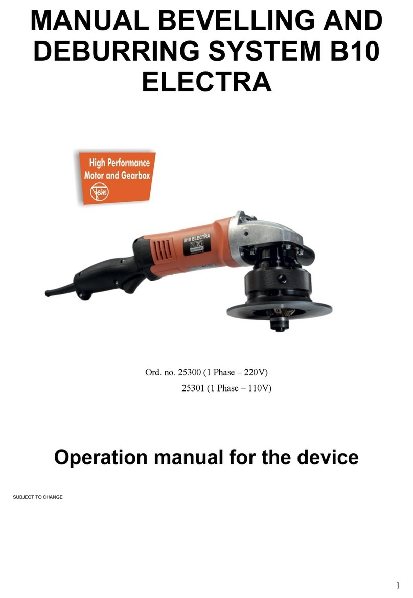
N.KO B5 User manual

1
N.KO spol. s r.o. IČO: 26161109
a Member of Richtr Group DIČ: CZ26161109
TÁBORSKÁ 398/22 č.ú.: 6626171001/5500
293 01 MLADÁ BOLESLAV email: [email protected] www.nko.cz
CZECH REPUBLIC TEL: +420 326 772 001
FAX: +420 326 774 279
DUNS:495075462 Výpis z obchodního rejstříku je veden u Krajského obchodního soudu v Praze, oddíl C, vložka75712
Beveling and Deburring Device B5
obj.č. 25 200
Operation manual
EN

2
General Safety Instructions
Please read this manual carefully and follow all relevant instructions and information.
When using electric tools, always adhere to the following safety instructions in order to prevent electric shock, fire
hazard and risk of injury:
Prior to every use, check device, power cable and plug! Do not use device with the switch damaged, when the
device cannot be switched on and off, or when the speed governor of the motor does not work reliably.
Only connect the plug to the power supply with the motor switched off.
Keep the device away from moisture and do not use in moist conditions.
Do not use the device in the proximity of flammable fluids or gases.
Ensure your workspace is well lit.
Always wear safety goggles.
Mind long hair and jewellery. They may become entangled in the rotating motor shaft.
Do not touch the cutter.
The work piece must be held and fixed tightly during the machining process.
Ensure the power supply cable is flat on the ground. Avoid tripping hazards.
Assume a firm stance when working.
Always disconnect from power supply before working on device or motor.
Protect yourself from electric shock.
Avoid physical contact with grounded parts.
Do not overload the device. Secure and ideal operation of the device is possible within the specified range of
performance of the drive motor only.
Do not use the device for purposes other than specified.
Do not misuse the power cable. Never carry the device by the cable. Never pull the cable when disconnecting
the plug from the power supply.
Protect the power cable from heat, oil, gasoline and sharp edges.
Always have damaged devices repaired by a specialist.

3
Unpacking the Device
Please check the packing for intactness and for possible damage by transport. In the case of damage by transport,
please notify the shipping agency immediately. The shipping agency will be liable for any occurring damage by
transport.
Connecting the Device
The device is supplied ready for operation.
Power supply 230V AC, ~6A, 50/60Hz (other countries 110V)
The 1,300 watt motor is equipped with a safety switch. If the plug is disconnected or if a power failure occurs while the
motor is running, the switch toggles to the OFF position.
When changing tools or adding accessories, disconnect the power plug from
the power supply to prevent accidents.
Read the manual carefully.
Specific Safety Instructions
Risk of injury to your hands! Do not reach into the machining zone. Hold the device with both hands!
Always run the cable away from the device and avoid sharp edges.
Risk of injury by hot chips.
Risk of injury by incorrect use!
Never touch tool with the device running.
Always hold device away from body.
Do not carry out overhead work with device.
Wear safety goggles.
Description
The B5 Deburring Device, item no 25200 is intended for deburring operation to inner and outer edges, radii and bores
from 20mm (=10mm radius).
Designed for steel, stainless steel, aluminium, aluminium alloys, brass and plastics machining jobs, for clean visible
edges and for the preparation of weld seams.
Tool-free adjustment of chamfer height.
Handy and powerful.
Triple cutting insert holder.
For industrial and handiwork purposes.
For producing visible edges in plant and
machine construction.
For use in ship building to remove sharp angles and edges in order to avoid paint chipping (corrosion
protection).
Optional:
Adjustable guidance-stop for outer edge Prod.-No.: 25207
25207

4
Specifications
Motor voltage: 230 volts, 50/60Hz
110V for other countries
Power: 1.300 W
Speed: 4.200 to 11.000min-1 with soft start, including thermo protection and overload limiter
Feed: manual
Feed rate: 1-4 m/min, dependant on chamfer width and material quality
Bevel Height and Width
The bevel width is calculated using the following equation: B = H x 1.414
Material and
Chamfer Width (2) mm
60°
45°
Tensile Strength
230V
230V
Steel 400 N/mm²
4
5
Steel 600 N/mm²
3
3
Stahl 800 N/mm²
2
2
Aluminium 250 N/mm²
6
6
Adjusting the bevel width and height
The bevel height can be adjusted using the support plate and is metered by means of the marker on the graduated
collar.
1 = Support plate.
2 = Knurled nut.
3 = Adjusting collar.
4 = Scale.
5 = upper limitation stone
a) Loosen knurled screw (2).
b) Turn support plate (1) until desired bevel height is achieved on graduated collar. The line markings on the scale
indicate the approximate bevel height in millimetres (one marking line is approx. 1mm). Use the markings on the
adjusting collar for fine adjustment. The distance from one marking line to the next corresponds to approx. 0.05mm
of chamfer height.
c) Tighten knurled screw (2).
d) The upper limitation stone (5) limited the bevel width

5
The bottom mark on the scale corresponds to a bevel height of approx. 1mm. It is recommended to
establish the exact chamfer height using a test job.
Graduated Collar:
On assembly, the device is adjusted to zero position. Zero position means a bevel height of 0.
Cutter Head 45 ° and radius 2,5
Cutter Head only for 60°
For very quiet operation and high stock-removing capacity the device has been equipped with triple milling heads, with
3 cutting inserts each. These cutting inserts have 3 cutting edges. They are the actual tools for bevelling and
deburring. Depending on the material they can be used for machining steel, aluminium, aluminium alloys and plastics.
Suitable for machining chamfers of
Cutting inserts seize: 13,47 x 3mm / PM25 M coated .
Cutter Head with Radius 2,5 Cutting Insert
For bevelling and deburring, use the 2.5 mm radius cutter head, Prod.-No. 25202 together
with the cutting insert Prod.-No. 25205.
Suitable for steel of up to 600N/mm²
Note: When inserting the milling head with radius, the supporting plate must be rotated to achieve the correct position
(compare 4.1).
Prior to machining steel and aluminium or aluminium alloys, it is recommended to spray the cutting edges with cutting
oil-adhesive-foam spotty in order to achieve enhanced machine ability of the edges and higher durability of the cutting
inserts.

6
Working with the B5 Deburring Device
The motor has a speed governor which can be used to adjust the speed to the relevant material. Infinitely variable from
6,000 to 10,000 min-1.
The ON/OFF switch is located on the handle.
Do not start working on the job until the correct speed has been reached.
Work on material.
When bevelling or deburring, the device must always be guided from left to right (up-cut
milling).
Operation with the device in all positions must be carried out with both hands.
Switching Off
1. Withdraw device from material.
2. Operate ON/OFF switch, the motor is turned off.
Attention:
Perform regular wear checks on cutting inserts. Sharp cutting inserts ensure efficient cutting performance and prevent
device from damage. Ensure to rotate or replace blunt or cracked cutting inserts when due.
Maintenance Intervals
Transmission and gearhead: Lubrication carried out by a specialist at every 100 operating hours or replace
lubricating grease.
Recommended grease: Grease off the type MSN 2 (Rhenus Norlith)
The first gear chamber needs to be filled up with 20 g
and the gear chamber on the motor side with 17 g.
Mounting thread on Clean and lubricate as necessary.
transmission housing:
Motor air vents: Clean as necessary.
Cutting inserts: Rotate or replace as necessary.
Ball bearing race: Replace as necessary.
Tool change: Push the shaft lock on the motor to the side and rotate milling head counter-
clockwise. Completely remove cutting insert holder.

7
Changing the Cutting Head
1) Loosen knurled screw and remove support plate with adjusting collar.
2) Press release button and engage drive shaft.
3) Loosen cutting head counter clockwise with hook wrench (supplied).
1 = Support plate with
adjusting collar.
1 = Release button.
2 = Drive shaft.
For refitting, proceed in reversed order. It will suffice to tighten the cutting head to hand tight with the hook wrench.
Changing the cutting inserts
1) Loosen cutting insert fastening bolt with torx wrench (T 10, supplied) and remove cutting inserts. Repeat this
procedure in the same way for each of the three cutting inserts.
2) Rotate or replace cutting inserts.
3) Refit cutting inserts with fastening bolt (tighten to hand tight).
There is no need to remove the cutting head when changing the cutting inserts. It will suffice to turn home the support
plate with the adjusting collar.
1 = Cutting insert.

8
Changing the Ball Bearing Race
Any worn out ball bearing must be duly replaced in order to prevent the chamfer surfaces from suffering irregular
machining.
1 = Ball bearing.
2 = Hex nut.
a) Loosen lower hex nut (2).
b) Pull away and replace ball bearing race.
c) Fit new ball bearing race with hex nut (2).
Replacing Carbon Brushes
With the carbon brushes worn out the motor will stall or the collector will be damaged. Have carbon brushes checked
and replaced by a specialist as necessary.
Only use original carbon brushes and follow instructions on rating plate.
Spare Parts
In order to ensure correct and rapid delivery of genuine consumables:
1) State part number according to attached exploded drawing.
2) Enter more order data such as:
Voltage data, quantity, machine type and purchase date.
3) State complete shipping address:
Correct address, desired type of dispatch.
Replacement inserts
Description Prod.-No.
Radius insert 2.5 mm 25205
Indexable insert BK84 for steel/stainless steel 22209
Torx screws, individually, for spare indexable inserts 25210
Replacement cutting heads
Description Prod.-No.
45° spare insert holder/radius R=2.5 (without indexable inserts) 25202
60° spare insert holder (without indexable inserts) 25203
Adjustable guide stop for outer edges 25207
Chip Removal and Cleaning

9
Regularly remove metal chips from device.
Always keep your working space clean.
For collecting chips, use our magnetic chip collector, Prod.-No. 18654:
Remember to turn off the device while collecting the chips. Never remove chips with your bare hands. Risk of injury!
Scope of Supply
According to the current offer.
Limitation of Liability
All technical information, data and instructions for use and maintenance of the device contained in this user manual
were last updated prior to delivery and have been of our previous experience and findings to the best of our
knowledge. This manual is subject to technical modifications on the basis of further development.
We do not assume liability for damage and malfunctions caused by operating errors, failure to follow the instructions of
these manual or inappropriate repairs. Any arbitrary modifications or alterations to the device are prohibited for safety
reasons and exclude a nonwarranty clause for resulting damage. Claims for damages, derived from whichever legal
ground, are excluded.
Warranty
The manufacturer grants a warranty of 12 months. For our Bevelling and Deburring Machines we grant guarantee
according to the legal and regional regulations (proven by invoice).This warranty is only valid with the carrying out of
the instructions of the Operation Manual and correct purpose of use.
The manufacturer is not legally liable for damages, caused by abuse, or misuse of instructions of this Operation
Manual.
Rights to claim under guarantee are out of question, in case the Bevel Milling Machine is, without written authorization
of the manufacturer, changed in construction or functional execution. If the electric tool is modified without our
authorization, this declaration will lose its validity and the guarantee expires.

10
EC Declaration of Conformity
N.KO,spol. s r.o.
Táborská 398//22
293 01 Mladá Boleslav
Czech republic
declare that the build of this
B5 type Deburring Device
complies with the provisions of the Safety of Machinery EC Directive as in 91/368/EEC.
The applied, harmonised standards are:
EN 292, Part 1, Safety of Machines
EN 60204, Part 1, Electrical equipment of machines
Technical documentation is available.
The user manual is supplied with the device.

11
Spare Parts List and Spare Part Drawing for Deburring Device B5

12
NKO-N°
Pos.
Menge
25195-001
1
1
Rotor s ventilátorem
armature with ventilation
230V 1,5kW
25195-017
17
1
Kompletní stator
stator complete
230V 1,5kW
25195-034
34
1
Skříň statoru
stator housing
reinorange
25195-035
35
2
Držák uhlíků
brush holder incl. flange
25195-037
37
1
Kuličkové ložisko
ball bearing 627-2RS-J/Y
7x22x7
25195-038
38
1
Kuličkové ložisko
ball bearing 627-2RS-J/Y
25195-039
39
2
Uhlík
carbon
230V
25195-040
40
2
Šroub statoru
stator-screw-fixation
25193-09
41
1
Vývodka
protection sleeve
25191-11
42
2
tapping screw
25191-12
43
1
Těsnění
insulation ring
25195-044
44
1
Vložka
supporting ring
25193-19
45
1
Kruhový magnet
ring magnet
25191-18
46
1
Talíř
disk
M3
25191-14
47
1
Šroub
countersink screw
M3x8
25195-049
49
1
Kryt ventilace
ventilation cover
25195-050
50
1
Záslepka
blinds
25195-052
52
1
Rukojeť levá
half shell handhold left
schwarz
25195-053
53
1
Rukojeť pravá
half shell handhold right
schwarz
25191-19
54
4
Šroub
tapping screw BZ
ø3.5x12
25191-47
55
2
Šroub
tapping screw B
ø3.5x25
25195-056
56
1
Vypínač
switch
2200.0601
25195-057
57
1
Klip kabelu
cable bridge
25195-058
58
1
feeding cable
VDE
25195-061
61
1
Regulace
electronic 230V
15 - 33k
189302115
62
1
Frézovací hlava 45° + R2,5 (pouze těleso
hlavy)
Cutter head 45° and R 2,5
(cutter head only; without cutting
inserts and startup ball bearings)
189302116
(62)
1
Frézovací hlava 60°
Cutter head 60°
25206
63
3
Břitové destičky
Cutting insert
25210
64
3
Šroub břitových destiček
Bolt
189302118
65
2
Ložisko vodící rolny
Deep groove ball bearing
686 ZZ
189302121
68
1
lock washer
16/1
189302119
66
1
Vodící rolna
Stop
189302120
67
1
Samojistící matice
Hex nut
M6
25195-100
100
1
lock washer
25195-102
102
1
Těsnění
sealing
25195-103
103
1
Pastorek
Pinion
25195-104
104
1
Matice
screw nut
M7
25195-105
105
1
Hlava
crosshead
25195-106
106
1
Kolík
blocking pin
25195-107
107
1
O-kroužek
o-ring
4.5x1
25195-108
108
1
Pružina
Spring
25195-109
109
1
Tlačítko
button
25195-110
110
1
Špice
needle bush
25195-111
111
4
Šroub
screw
25195-117
117
1
Vřeteno
spindle
25195-118
118
4
Šroub
screw
M4 x 20
25195-119
119
1
Těsnění
sealing flange
25195-120
120
1
Podložka
washer
25195-121
121
1
O-kroužek
o-ring
50x2
25195-122
122
1
Jistící kroužek
Adjusting ring
25195-123
123
1
Kolo
spindel gear

13
25195-124
124
1
Držák
handhold
25195-125
125
1
Talíř vedení
Disc
25195-126
126
1
Doraz
stop
25195-127
127
2
Kámen
tensioning block
25195-128
128
1
Kámen max. nastavení
limit stop block
25195-129
129
2
Ložisko
deep groove ball bearing
6004 1RZ
25195-130
130
1
Podložka
lock washer
DIN 471 Ø20
25195-131
131
1
Ségrovka
snap ring
DIN 472 Ø42
25195-132
132
1
O-kroužek
o-ring
Ø52 x 3 NBR70
25195-133
133
3
Šroub
countersink screw
M4 x 8
25195-134
134
2
Křídlová matice
wing screw
M5 x 10
25195-135
135
2
Kolík
dowel pin
Ø4 x 10
25195-136
136
1
Šroub aretační
knurled screw
25195-137
137
1
Šroub
cylinder head screw
M5 x10
25195-200
200
16
Tuk převodovky
grease
N.KO, spol. s r.o.
Táborská 398//22
293 01 Mladá Boleslav
Czech republic
This manual suits for next models
1
Other N.KO Tools manuals
