manuals.online logo
Brands
  1. Home
  2. •
  3. Brands
  4. •
  5. Kramer
  6. •
  7. Control Unit
  8. •
  9. Kramer TBUS-5i User manual

Kramer TBUS-5i User manual

Other Kramer Control Unit manuals

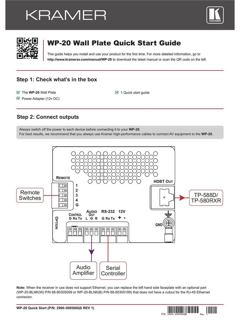
Kramer WP-20 User manual

Kramer

Kramer WP-20 User manual

Kramer RC-7RL User manual

Kramer

Kramer RC-7RL User manual

Kramer RC-52A User manual

Kramer

Kramer RC-52A User manual

Kramer RTBUS-25xl User manual

Kramer

Kramer RTBUS-25xl User manual

Kramer TBUS-201xl User manual

Kramer

Kramer TBUS-201xl User manual

Kramer TBUS-203xl User manual

Kramer

Kramer TBUS-203xl User manual

Kramer VM-8UX User manual

Kramer

Kramer VM-8UX User manual

Kramer OSP SFP+ Specification sheet

Kramer

Kramer OSP SFP+ Specification sheet

Kramer TBUS-202xl User manual

Kramer

Kramer TBUS-202xl User manual

Popular Control Unit manuals by other brands

Seitz 14A80 user manual

Seitz

Seitz 14A80 user manual

Wilo RS485 Installation and operating instructions

Wilo

Wilo RS485 Installation and operating instructions

Becker CentralControl CC41 Commissioning Instruction

Becker

Becker CentralControl CC41 Commissioning Instruction

SICK CDB650 operating instructions

SICK

SICK CDB650 operating instructions

Panduit NetKey NKP5E88M Series installation instructions

Panduit

Panduit NetKey NKP5E88M Series installation instructions

MX Options Concentric Petite Fitting instructions

MX

MX Options Concentric Petite Fitting instructions

Clean Water Systems Fleck 2510 Installation & start?up guide

Clean Water Systems

Clean Water Systems Fleck 2510 Installation & start?up guide

Fairchild FSB44104A user guide

Fairchild

Fairchild FSB44104A user guide

LEGRAND Wattstopper LMIN-104 installation instructions

LEGRAND

LEGRAND Wattstopper LMIN-104 installation instructions

PMK ATT10BNCS instruction manual

PMK

PMK ATT10BNCS instruction manual

Tektronix TDS3FFT user manual

Tektronix

Tektronix TDS3FFT user manual

Woodward easYgen Technical manual

Woodward

Woodward easYgen Technical manual

Balluff BNI EIP-502-105-R015 user guide

Balluff

Balluff BNI EIP-502-105-R015 user guide

NXP Semiconductors TWR-LS1021A Getting started

NXP Semiconductors

NXP Semiconductors TWR-LS1021A Getting started

Advantech PCM-3117 Startup manual

Advantech

Advantech PCM-3117 Startup manual

Danfoss MCO 101 manual

Danfoss

Danfoss MCO 101 manual

Moons' Lin Engineering R701P user manual

Moons'

Moons' Lin Engineering R701P user manual

Aventics RV1 operating instructions

Aventics

Aventics RV1 operating instructions

manuals.online logo
manuals.online logoBrands
  • About & Mission
  • Contact us
  • Privacy Policy
  • Terms and Conditions

Copyright 2025 Manuals.Online. All Rights Reserved.

Installing the TBUS-5i Insert Plate
The TBUS-5i Insert Plate (see Figure 1) is designed as a replacement for the
connecting surface of the TBUS-5, letting you install Kramer inserts and
modules
1
according to your needs:
2 x Blank Plate
Cable
Pass-through
Power Module
Opening
Figure1:TheInsertPlate
The inserts can be installed before or after installing the TBUS-5i unit.
To mount an insert, do the following:
1. Unscrew the blank insert plate
2. Place and align the insert under the opening, insert the two screws to fix the
insert in place, and tighten them.
To install the TBUS-5i Insert Plate, do the following:
1. Remove the five height adjustment screws (see item 5 in Table 1 of the
TBUS-5 user manual) on the sides of the enclosure while supporting the
surface from underneath with your hand (keep the screws).
2. Take out the connecting surface.
 
1
The complete list of Kramer inserts and interfaces is on our Web site at
www.kramerelectronics.com
3. Unscrew the two power module screws that fasten the power module to the
connecting surface, keep the screws, and remove the power module from
below.
4. Insert the power module into the designated opening (make sure you place
the power module in the correct position) on the Insert Plate and tighten
with the two power module screws.
5. Place the Insert Plate inside the enclosure, and raise or lower the
connecting surface to the required height. Fasten the screws, and tighten
them in place.
Height
Adjustment
Screw
Power Module Screw
Figure 2: Removing the Height Adjustment Screws

 
 
 
TBUS-5i
"Insert Plate"
Installation Instructions
 
 
For the latest information on our products and a list of Kramer distributors, visit our
Web site: www.kramerelectronics.com 
 
 
 
 
Kramer Electronics, Ltd.
Web site: www.kramerelectronics.com
E-mail: info@kramerel.com
P/N: 2900-001205 REV 1