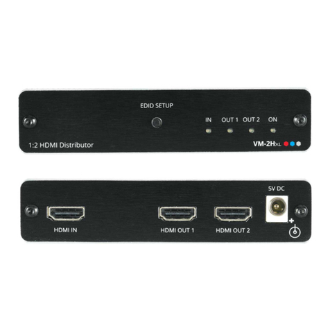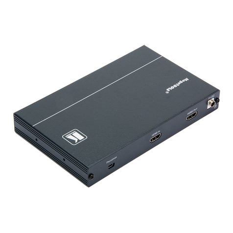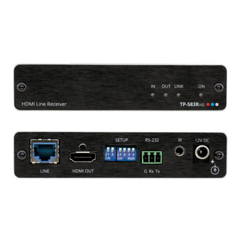
Install VS-21DT using one of the following methods:
•Attach the rubber feet and place the unit on a flat surface.
•Fasten a bracket (included) on each side of the unit and attach it to a flat
surface (see www.kramerav.com/downloads/VS-21DT).
•Mount the unit in a rack using the recommended rack adapter
(see www.kramerav.com/product/VS-21DT).
•Ensure that the environment (e.g., maximum ambient temperature & air
flow) is compatible for the device.
•Avoid uneven mechanical loading.
•Appropriate consideration of equipment nameplate ratings should be
used for avoiding overloading of the circuits.
•Reliable earthing of rack-mounted equipment should be maintained.
•Maximum mounting height for the device is 2 meters.
Step 4: Connect inputs and outputs
Always switch OFF the power on each device before connecting it to your VS-21DT.
To achieve specified extension distances, use the recommended Kramer cables available at www.kramerav.com/product/VS-21DT.
Using third-party cables may cause damage!
DIP-switches Setup:
A switch that is down is on; a switch that is up is off. By default, both switches are up (off).
Video Switching Selection:
INPUT 1 is the default priority and is automatically switched to the output.
INPUT 2 is the default priority and is automatically switched to the output.
The last connected source is switched to the output (a reactivated or reconnected source
becomes the new “Last Connected” source).
Contact Closure Switches (Manual Override):
Controlling via the remote contact closure pushbuttons overrides all DIP-switch settings and automatic switching until
the manually selected source disconnects, becomes inactive or the VS-21DT is powered off.
Momentarily connect REMOTE IN 1 to PIN G (ground).
Momentarily connect REMOTE IN 2 to PIN G (ground).
Step 5: Connect power
Connect the power cord to VS-21DT and plug it into the mains electricity.
Safety Instructions (See www.kramerav.com for updated safety information)
Caution:
•For products with relay terminals and GPI\O ports, please refer to the permitted rating for an external connection, located next to the terminal or in the User Manual.
•There are no operator serviceable parts inside the unit.
Warning:
•Use only the power cord that is supplied with the unit.
•Disconnect the power and unplug the unit from the wall before installing.

