Kramp KRED-D User manual

EN
www.kramp.com
for solenoid operated proportional valves
UNIVERSAL ELECTRONIC DRIVER
TYPE KRED
USER GUIDE

EN
03/2016Universal electronic driver type KRED for solenoid operated proportional valves
UNIVERSAL ELECTRONIC DRIVER TYPE KRED
fOR SOLENOID OPERATED PROPORTIONAL VALVES
KEY fEATURES
• Microcontrollerdesign
• Independentadjustments(rampup-rampdown)
• 4digitleddisplay
• Displayandadjustactualvalues(current&voltage)
• Easyaccesstothemenusetup
• Wideramptimerange
• Simplecontrolwithanaloginput,locallysuppliedreferencevoltage
• Noheatsinkrequired
• Electroniclimitingcircuit/shortcircuitproof
• Reversepolarity,commandinputprotection
• Loadcanbeconnectedanddisconnectedlive
1 DESCRIPTION 2 TEChNICAL DATA
Thedrivercontrolsonesolenoidofaproportionalvalve.
Hisconstructionpermitsaneasyassemblydirectlyonthe
DINrailoftheelctriccabinet.Bytheuseoftwoselectors
itispossibletoeasilycongurealltheparameterswithout
theneedofspecialtoolsorprogrammingdevices.
A4digitleddisplayshowsallthenecessariesinformations.
Versions:
KRED-Sisforsinglesolenoidproportionalvalves
KRED-Disfordoublesolenoidproportionalvalves
Operating voltage: 9-36VDC
Maximum output current: 3,00A
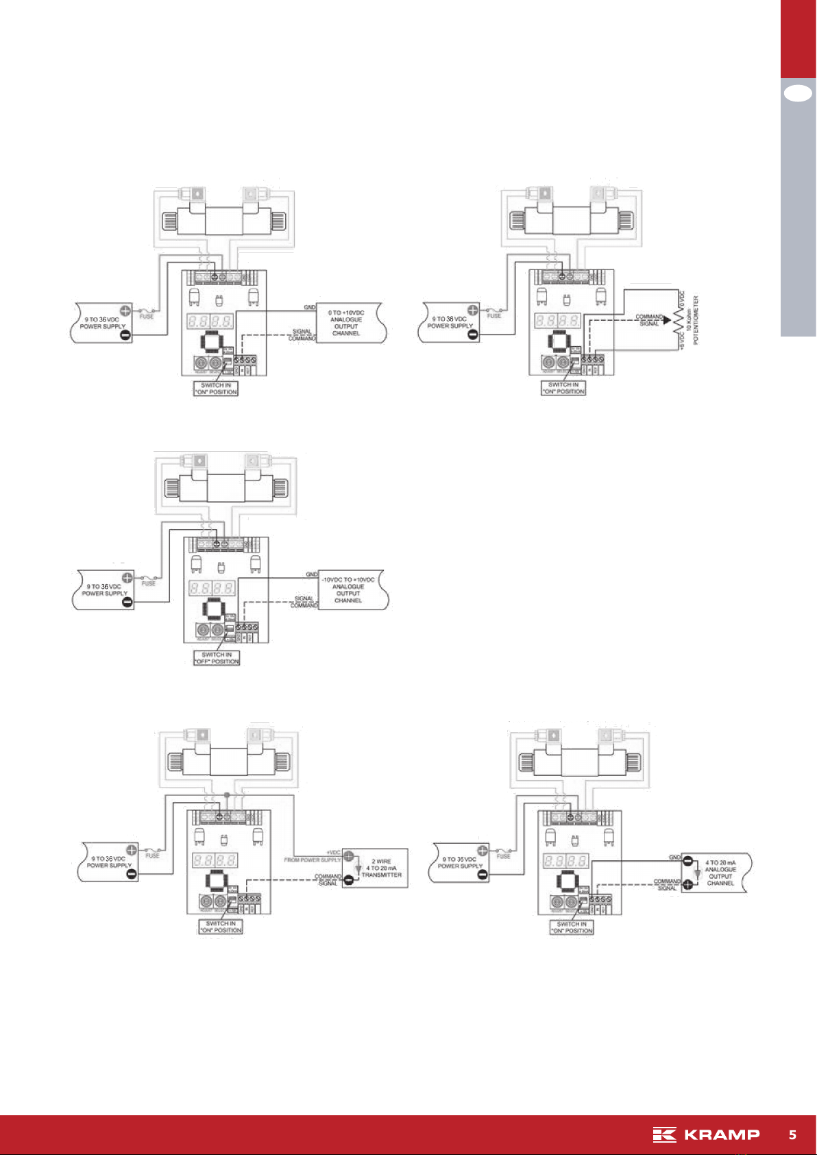
Input signal: 0-5V;0-10V;4-20mA
Maximum ramp time: 99,5s
Linearity: 40-450Hz
Operating Temperature: -40..80°C
Mounting:DINrail(open)
3 SET-UP PROCEDURE
Available input selection KRED-S Available input selection KRED-D
DIPSwitchinON/UPposition
"in":10-->(0to10V)**default "in":10-->(0to10V)**default
"in":5-->(0to5V) "in":5-->(0to5V)
"in":420-->(4to20mA) "in":420-->(4to20mA)
DIPSwitchinOFF/Downposition
"in":-10-->(-10to10V)
1. Atpowerup,thedisplaywillshoweithertheoutputcurrentsignalortheinputsignal(Defaultdisplaysettingshowsthe
outputsignal).Thedecimalpointwillbeashing.
2. RotateSELECTtoentertheset-upmode.Parameterabbreviationisindicatedonthedisplay
3. Whenyoureachthesettingyouwanttomodify,rotateADJUSTupordowntothedesiredvalue.
4. Tomodifyanothersetting,rotateSELECTagainandrepeat.
5. TheDriverisfullyfunctionalduringtheset-upprocedurewithanyadjustmentseffectiveimmediately.
6. Inordertowritethenewsettingsinthememoryandreturntonormalmodeofoperation,rotate„SELECT“untilthe
displayshows„SR“andthenrotate„ADJUST“from0to1orwaitfor100seconds.
7. Ifyoudonotwanttosavethenewsettingsyouhavejustmodied,youmustdisconnecttheDriverfromthepowersupply
beforetheendofthe100secondstorestoreprecioussettings.
8. Aftersavingparameterstomemory,thedecimalpointwillbeashingandtheDriverdisplaywillbebackshowingeither
theoutputcurrentsignalorinputsignaldependingonyour„di“selection.
9. Tostartovercompletely,youcanrestorethefactorysettingsbyrotatingSELECTtorFPandthenrotateADJUSTuppast
10forthedisplaytoreset(NOTEforStep9:youmayhavetoadjustyourInputSignalSettingagainifyouresettofactory
settings.)
2

EN
03/2016 Universal electronic driver type KRED for solenoid operated proportional valves
4 SETTING RANGES
Parameter Description Adjustable
range
Hi* HIGH,MaximumCurrentOutput 0,20-3,00A
Lo* LOW,MinimumCurrentOutput(seenote1) 0,00-2,99A
rUP* RAMPUP,TimeforOutputtoincreasefrommintomax 0,0-99,5s
rdn* RAMPDOWN,TimeforOutputtodecreasefrommaxtomin 0,0-99,5s
Cdb COMMANDDEADBAND,Outputdisabledifcommandsignalislessthendeadband 0-5%
JC JOYSTICKCALIBRATION/INPUTOFFSETCOMPENSATION,midpointbetweenaandbat50% 40-50-60%
dFr DITHERFREQUENCY 40-450Hz
in INPUTSIGNALSELECTION:
5-Voltagesignal
20-Voltagesignal
420-Currentsignal
0-5V
0-10V
4-20mA
di DISPLAYEDSIGNALFORTROUBLESHOOTING:
0-Commandsignal[V]or[mA]
1-Outputsignal[A]
**Flashingdecimalpointisanindicatorforpresentdisplaymode**
-Fastashingdecimalpoint,severalashespersecondindicatesdi=0
-Slowashingdecimalpoint,1persecondindicatesdi=1
-NoashingdecimalpointornodecimalpointindicatesdisplayinSETTING/ADJUST
SA SAVESETTINGS
rFP RESETFACTORYPARAMETERS(seenote2)
Err ERRORDETECTIONSTATE,shortcircuit,reversepolarityprotectionanddetection:
0-Error0-Noerrors
1-Error1-OvercurrentindriverlikelyduetoshortcircuitinSolenoid
2-Error2-Currentexceeding20mAin4-20mAinputmode
CLr CLEARERROR,cleardriverorerrorstate(seenote2)
NOTE1 WhenadjustingtheHIandLOparameters,notetheHIparametervaluecannotbeadjusted
belowtheLOparametervalueaswelltheLOparametervaluecannotexceedtheHIparameter
value.
NOTE2 AdjustParametervalueuppast9tooperatethiscommandsetting
NOTE3 *inKRED-DparameterwillbeaHiorbHi(asexample)whenasolenoidorbsolenoidis
congured
5
3

EN
03/2016Universal electronic driver type KRED for solenoid operated proportional valves
6 SChEMATICS KRED-S
1) EXTERNAL INPUT SIGNAL CONNECTION
(” in” set to ”10”)
2) POTENTIOMETER CONNECTION
(” in” set to ”5”)
3) RAMP UP & DOWN ONLY OPERATION
(” in” set to ”5”)
4) EXTERNAL INPUT SIGNAL CONNECTION 4-20 mA
(” in” set to ”420 ”)
5) TWO WIRE TRANSMITTER INPUT CONNECTION 4-20 mA
(” in” set to ”420 ”)
Note:for“0to5VDC”and“0to10VDC”commandimputdrivers,itisrecommendedtouseindipendentnegativeconductors
forpowersupplyandanalogueoutputchannel(PLC/PC)tomantaincommandsignalaccuracyduetovoltagedroponlong
cableruns.
4

EN
03/2016 Universal electronic driver type KRED for solenoid operated proportional valves
SChEMATICS KRED-D
1) EXTERNAL INPUT SIGNAL CONNECTION
(” in” set to ”10”)
2) POTENTIOMETER CONNECTION
(” in” set to ”5”)
5) EXTERNAL INPUT SIGNAL CONNECTION
4) TWO WIRE TRANSMITTER INPUT CONNECTION
(” in” set to ”420 ”)
3) EXTERNAL INPUT SIGNAL CONNECTION
(” in” set to ”-10”)
(” in” set to ”420 ”)
Note:for“0to5VDC”and“0to10VDC”commandimputdrivers,itisrecommendedtouseindipendentnegativeconductors
forpowersupplyandanalogueoutputchannel(PLC/PC)tomantaincommandsignalaccuracyduetovoltagedroponlong
cableruns.
5

EN
03/2016Universal electronic driver type KRED for solenoid operated proportional valves
6
7 ADjUSTMENT KRED
0% 3% 5% 25%
1,00
2,00
3,00
0,00
100 Hz 200 Hz
0 50 100
0.00
1.00
2.00
3.00
0
0.00
1.00
2.00
3.00
150 0
500
0
0 V
4 mA
3.00
2.00
1.00
5 or 10 V
20 mA
3.00
0.00
0 V
4 mA
2.00
1.00
5 or 10 V
20 mA
3.00
0.00
5 10
Adjustment of Maximum:
(High) / parameter „Hi“
Maximum Current output 0,20 - 3,00 A
Time[s] Time [s]
Command signal [V or mA]
Solenoid current [A]
Adjustment Ramp
(Ramp up) / parameter „rUP“
Time for Output to Increase from min to max 0 - 99,5 s
Adjustment Ramp
(Ramp down) / parameter „rdn“
Time for Output to Decrease from max to min 0 - 99,5 s
Adjustment (Command deadband) /parameter „Cdb“
Output disabled if command signal less than deadband
0 - 5 % of the maximum Command signal
DITHER FREQUENCY / parameter „dFr “
Frequency settable in a range of 40 - 450 Hz
Command signal [V or mA] Time [ms]
Command signal [V or mA]
Solenoid current [A]
Adjustment of minimum
(Low) / parameter „Lo“
Maximum Current output 0,00 - 2,99 A

EN
03/2016 Universal electronic driver type KRED for solenoid operated proportional valves
7
ADjUSTMENT KRED
This product has been designed and tested to meet specic standards outlined in the EMC 2004/108/EC
Emission: EN 61000-6-4:2007
Immunity: EN 61000-6-2: 2005, EN 61000-4-2, EN 61000-4-4, EN 61000 4-6
Table of contents
Other Kramp Measuring Instrument manuals
Popular Measuring Instrument manuals by other brands

PCE Instruments
PCE Instruments KREBS PCE-RVI 5 manual

ADInstruments
ADInstruments Lt Sensors Series quick start guide

REO
REO 32734 User and operational manual

Agilent Technologies
Agilent Technologies WireScope 350 user manual

VIERLING
VIERLING ECOTEL C6 operating instructions

VEE GEE
VEE GEE CTX-1 Operation manual

Center
Center SE-323 instruction manual

PCB Piezotronics
PCB Piezotronics IMI SENSORS 637A06 Installation and operating manual

Interface
Interface ITL Operator instructions

PCE Health and Fitness
PCE Health and Fitness PCE-CT 80HP user manual

Hanna Instruments
Hanna Instruments HI96729 instruction manual

bentrup
bentrup TM 100 operating instructions