Kraus KD1US17B User manual

Kraus Undermount Stainless Steel Sink Installation Instructions
For the Attention of the Customer and the Installer:
1. For best results, Kraus recommends that the solid surface countertop cut-out should only be prepared by
a professional fabricator, and undermount sinks should only be installed by a professional installer.
2. The enclosed paper template represents Kraus recommended countertop cut-out specication and sink
mounting style.
3. Sink installation and countertop cut-out choices are not limited to Kraus specications. Installer and
customer must discuss these options, and reach an agreement on alternate countertop cut-out dimensions
and sink installation methods prior to preparation of the countertop. Kraus will not be held responsible
for alternate choices of sink installation and countertop cut-out.
4. In addition to the Kraus paper template, electronic (.dxf) les for countertop cut-outs are available on the
Kraus website www.kraususa.com
5. Sink mounting requirements will vary according to countertop selection. Hardware for mounting the sink
to the countertop is not included, and should be specied by the countertop fabricator for the specic
countertop selection.
6. Sink may have sharp edges, please use caution when handling.
7. Inspect the sink unit prior to installation to conrm acceptance. Do not install a damaged unit.
8. Kraus USA is not responsible for any damage to sink or countertop incurred during installation.
9. Please follow all local plumbing and building codes.
KRAUS CUSTOMER SERVICE
Toll-free: 1.800.775.0703
Phone: 1.646.461.9199
Email:
customerservice@kraususa.com
Hours:
9:00am to 8:00pm (EST) Monday thru Friday
INSTALLUS 1 May 2017
Installation Instructions
KD1US17B, KD1US25B, KD1US33B and KD1UD33B

2
www.kraususa.com INSTALLUS 1 May 2017
Please note Kraus recommended sink mounting specications A and B:
KRAUS RECOMMENDED
SPECIFICATION B: 1/8” OVERHANG
OPTIONAL CHOICE AT DISCRETION OF CUSTOMER
KRAUS RECOMMENDED
SPECIFICATION A: 1/4” REVEAL
Flush t installation is NOT recommended by Kraus.
Exposure of silicone joint is not considered aesthetically acceptable.
Precise match of sink and countertop cut-out is extremely dicult.
FLUSH FIT INSTALLATION
Installation Instructions
KD1US17B, KD1US25B, KD1US33B and KD1UD33B

3
www.kraususa.com INSTALLUS 1 May 2017
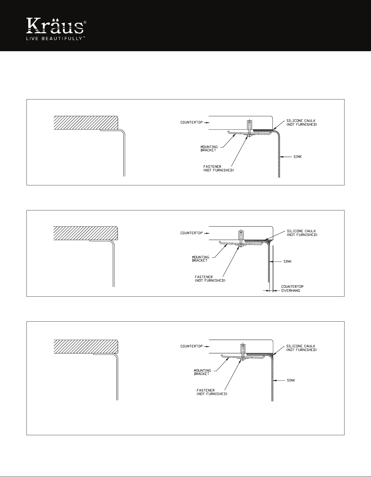
The following instructions apply only to Kraus-recommended sink mounting specication A and B.
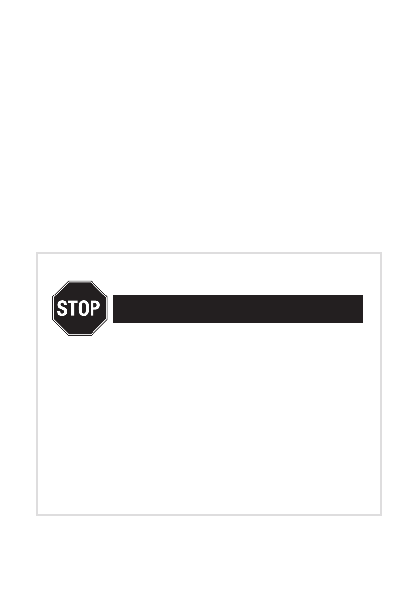
1. Position undermount sink template on countertop, centered within the sink base cabinet unit. Make sure to provide
adequate clearance from the countertop backsplash, with room for mounting faucet and ttings behind the sink.
Avoid any potential interference with cabinet bracing.
2. Countertop cut-out may be prepared by using either the paper template included within the sink carton,
or referencing the .dxf le found on www.kraususa.com
2A. Trace a line around the paper template. Cut along the inside of this line to create opening in countertop.
2B. Select the dxf le for the Kraus model purchased. CNC machine the countertop cut-out based on this dxf le.
3. Locate and drill the sink fastener mounting holes (following the countertop manufacturer’s instructions).
Type of fasteners should be recommended by countertop supplier.
4. Loosely fasten sink mounting clips to countertop.
5. Apply a bead of silicone caulking (not included) evenly along the sink ange.
6. Position and align sink to the countertop. Tighten fasteners until sink mounting clips are snug against the sink ange.
7. Check alignment of sink to cut-out opening, and adjust if necessary. Tighten fasteners evenly. DO NOT overtighten.
8. Wipe up and remove any excess silicone from the countertop cut-out edge.
Installation Instructions
KD1US17B, KD1US25B, KD1US33B and KD1UD33B
Kraus Recommended Optional Accessories
NOTE:Kraus recommends using a high-quality dish grid with your stainless steel sink to protect the bottom of the basin
from wear and tear. To ensure the proper t, we recommend the following matching grids:
DEX™ SERIES
STAINLESS STEEL SINK
MODEL NO. RECOMMENDED
DISH GRID
MODEL NO.
1.
17” Undermount Single Bowl
Stainless Steel Bar Sink
KD1US17B
15” Stainless Steel
Kitchen Sink Grid
BG1517
2.
25” Undermount Single Bowl
Stainless Steel Kitchen Sink
KD1US25B
23” Stainless Steel
Kitchen Sink Grid
BG2317
3.
33” Undermount Single Bowl
Stainless Steel Kitchen Sink
KD1US33B
31” Stainless Steel
Kitchen Sink Grid
BG3117
4.
33” Undermount Double Bowl
Stainless Steel Kitchen Sink
KD1UD33B
15” Stainless Steel
Kitchen Sink Grid
BG1517 (x) 2

4
www.kraususa.com INSTALLDS 1 May 2017
KRAUS CUSTOMER SERVICE
Toll-free: 1.800.775.0703
Phone: 1.646.461.9199
Email:
customerservice@kraususa.com
Hours:
9:00am to 8:00pm (EST) Monday thru Friday

INSTALLATION MANUAL
Oletto™Single Handle
Commercial Style Kitchen Faucet
KPF-2631
www.kraususa.com I Toll Free: 1.800.775.0703 I © 2017 Kraus USA Inc. I REV. November 20, 2017

1
Congratulations on the purchase of your new
Kraus plumbing xture!
Please keep the box and packaging materials until your product is
completely installed. If you have any questions, require technical
assistance, or have any problems with your product:
Please contact our Customer Service Team
1-800-775-0703 / customerservice@kraususa.com
Have the model number available, and retain a copy of your receipt
with purchase date for reference.
If for any reason this product does not meet your expectations,
please be sure to repack this product in the original box and
packaging material to avoid damage during transit.
DO NOT RETURN TO STORE

2
Prior to Installation:
• Make sure you have all necessary parts by checking the diagram and parts list. If
any part is missing or damaged, please contact Kraus Customer Service at 800-
775-0703 for a replacement
• Turn off the hot and cold water supply at the angle stops and turn on the old
faucet to release any built up pressure. Remove existing faucet. Clean sink or
countertop to remove any debris, plumber’s putty, or silicone
• Place bucket under angle stops. Turn on to ush any debris prior to installing new
plumbing. Shut off angle stops
• Pre-drilled hole size requirement: 1-3/8” (min) – 1-1/2” (max)
• Max countertop thickness without deck plate: 1-1/2”
• Max countertop thickness with deck plate: 1”
• 1, 2, or 3 hole installation
Without deck plate:
With deck plate:
1/16” (1mm) min.
1-1/2” (38 mm) max.
Ø 1-3/8” (35 mm) min.
Ø 1-1/2” (38 mm) max.
1/16” (1mm) min.
1” (25.4 mm) max.
Ø 1-3/8” (35 mm) min.
Ø 1-1/2” (38 mm) max.
1
2
Designated Mark
Hot
Upward
Black
Cold
1A 1B
234
567
G
G
EEF
G
G
G
G
F
F
F
E
E
H
E
E
A
A
I
B
J
D
D
CD
G
Half Moon Locking Nuts Half Moon Locking Nuts
Rubber Caps
G
Tools you will need:
Adjustable Wrench Safety Goggles Bucket Silicone Sealant
6 5/8”
5 4/5”
3/8”
(10mm)
7/8”
19.7
º
(22mm)
8 5/16”
1 1/4-18UNF-2A
(21mm)
10 1/8”
(257mm)
1 3/8”
(35mm)
3 3/4”
(168mm)
(147.3mm)
(96mm)
∅ 1 3/4”
(∅ 45mm)
∅ 1 15/16”
(∅ 50mm)
9/16”-18UNEF
27mm ~ 41.3mm
1 1/16” ~ 1 5/8”
∅ 1 15/16”
(∅ 50mm)
12 7/16”
(316mm)
1 5/8”
(42.5 mm Max)
7A
8B
8C
8D
8A
7A
8B
8C
8D
8A
Adjustable wrench Phillips screwdriver
Tools You Will Need
Hex wrenchSilicone Sealant
A
I
D
J
F
B
G
C
H
E

3
Diagram and Parts List
A. Spray Head
B. Faucet Body
C. Deck & Putty Plate
D. Supply Hose
E. Hot & Cold Waterlines
F. Spray Hose
G. Weight
H. Quick Connect
I. Hex Wrench
i1. 2.5mm
i2. 4mm
J. Base
A
I
J
B
D
F
G
H
E
C

4
Faucet Dimensions
9 1/4"
233mm
1 3/8"
35mm
2 1/2"
62mm
25
65
7 1/8"
181mm
1"
25mm
10 1/4"
260.5mm
8 3/4"
223mm
279mm
4 1/4"
106.5mm
11"
22 1/8”
562mm
9/16-24UNEF-2B
Step 1A: Install base without deck & putty plate
Insert base (J) into sink or
countertop with “FR↑NT” facing
forward. Tighten screws on base
(J) with 4mm hex wrench (i2)
until base is secure on sink or
countertop
Installer Tip: Rotate the
two half-moon shaped
locking nuts inward before
inserting base (J) into sink or
countertop
Half Moon Locking Nuts
J
i2

5
Step 1B: Install base with deck & putty plate
Place a bead of clear silicone
sealant (not included) around the
edge of the putty plate (C). Secure
deck & putty plate (C) on sink or
countertop. Insert base (J) into
hole of deck & putty plate (C) with
“ FR↑NT” facing forward. Tighten
screws on base (J) with 4mm hex
wrench (i2) until base is secure on
deck & putty plate (C)
Step 2: Install faucet
Without deck plate:
With deck plate:
1/16” (1mm) min.
1-1/2” (38 mm) max.
Ø 1-3/8” (35 mm) min.
Ø 1-1/2” (38 mm) max.
1/16” (1mm) min.
1” (25.4 mm) max.
Ø 1-3/8” (35 mm) min.
Ø 1-1/2” (38 mm) max.
1
2
Designated Mark
Hot
Upward
Black
Cold
1A 1B
234
567
G
G
EEF
G
G
G
G
F
F
F
E
E
H
E
E
A
A
I
B
J
D
D
C
D
G
Half Moon Locking Nuts Half Moon Locking Nuts
Rubber Caps
G
Installer Tip: Rotate the two
half-moon shaped locking
nuts inward before inserting
base (J) into deck plate (C)
2
J
i2
E
E
E
FD
E
D
F
Remove Quick Connect (H)
from spray hose (F). Insert
spray hose (F) into small
hole of base (J). Insert hot
& cold waterlines(E) and
supply hose (D), one by
one, in large hole of base

6
Step 3: Secure faucet
Align arrow on faucet body (B) with arrow on base (J). Attach faucet body (B)
to base (J). Secure faucet body (B) by tightening the set screw with 2.5mm
hex wrench (i1)
Installer Tip: Please loosen set screw from faucet body (B) prior to securing
to base (J)
Note: “ “ on base should be in
alignment with “ “ on faucet body.

7
Step 4: Connect waterlines to main valve
Thread hot & cold waterlines (E) onto angle stops. Tighten with adjustable
wrench until snug. Turn on the angle stops and check for leaks (DO NOT
TURN FAUCET ON)
Installer Tip: Use two wrenches when securing waterlines to angle stops
to prevent kinking, as shown in picture
E
Hot
E
E
Cold

8
Step 5: Connect quick connect
F
F
F
D
D
D
H
Attach Quick Connect (H) with black end onto spray hose (F) until you hear
a click. Attach the other end onto the supply hose (D) until you hear a click.
F
D
Installer Tip: Remove the plastic caps from the supply hose D and spray
hose F prior to attach the quick connect

9
Step 6: Install Weight
Attach weight (G) on the designated mark on the spray hose (F)
G
F
Designated Mark

10
Step 7: Flush Faucet
Remove spray head (A). Hold tip of spray hose. Turn faucet on for 1 minute
to ush any debris. Reconnect spray head (A)
A A

Replacement Part List
1. Spray Head
2. Plastic Sleeve
3. Spray Hose
4. Set Screw
5. Catridge
6. Locking Nut
7. Catridge Cover
8. Metal Handle
9. A Index Button
B Set Screw
10. Quick Connect
Assembly
11. Cover Plate
12. Putty Plate
13. Base
14. Weight
15. Hex Wrench
(2.5mm)
16. Hex Wrench
(4mm)
1
2
3
45
6
7
8
10
14
11
12
13
16
15
9A
9B

12
Trouble - Shooting
If you have followed the instructions carefully and your faucet still does not work
properly, take the following corrective steps:
PROBLEM CAUSE ACTION
Water will not shut off
completely
Cartridge(5) may need
to be adjusted or
replaced
Remove index button
(9B). Loosen set screw
(9A) with 2.5mm hex
wrench (15). Remove
metal handle (8).
Remove cartridge
cover (7) by hand only.
Remove locking nut
(6) with an adjustable
wrench. Remove ceramic
disc cartridge (5). Check
for cracks
Leaking from between
spray head and hose
Washer may be missing
or not seated correctly
in hose
Make sure washer is
present and seated
correctly in hose
Care & Maintenance
*To keep the product clean & shining, follow the steps below:
1. Rinse with clean water & dry with a soft cloth
2. Do not clean with soaps, acid, polish, abrasives, or harsh cleaners
3. Do not use cloth with a coarse surface
4. Unscrew the aerator and clean when necessary
*This installation manual is subject to change without further notice.
1
10
279
10 31/32”
Minimum distance 90mm
Less than 90mm
Cold Water
32 3/32”
Ø35~Ø38
1
23
10
9
11
12 13
Hexagon Nut
Hot
Water
Cold
Water
2 3
1
45
7
6
8
45
67
8
Ø1 3/8”~Ø1 1/2”
815
194
7 5/8”
Ø1 3/8~Ø1 1/2”
30˚
10 11
Close
Open Left
Hot Water
Push
25˚ 90˚
12
13
8
7
Ø35~Ø38
Max35
217
8 17/32”
Max1 3/8”
9
11
12 13
2
3
4
5
6
7
8
Download the Kraus Care & Maintenance Guide at:
http://www.kraususa.com/maintenance

13
Codes/Standards Applicable:
FAUCET WARRANTY
Kraus products are manufactured and tested to the highest quality standards by Kraus USA Inc.
(“Kraus”). Kraus extends this warranty to the original purchaser for personal household use of the
“Faucet” in its original location. The warranty is non-transferable.
Kraus warrants the structure and finish of the product to be free from defects in material and
workmanship under normal usage for the lifetime of the product. The warranty commences from
the initial date of purchase by the owner or trade professional, from an authorized Kraus dealer,
through the lifetime of the original owner or end-user.
Kraus warrants the mechanical component (sprayhead assembly) of the product to be free from
defects in material and workmanship under normal usage for a period of one (1) year. The warranty
commences from the initial date of purchase by the owner or trade professional, from an authorized
Kraus dealer, through the one (1) year term of the original owner or end-user.
Kraus warrants the mechanical component (cartridge) of the product to be free from defects
in material and workmanship under normal usage for a period of five (5) years. The warranty
commences from the initial date of purchase by the owner or trade professional, from an authorized
Kraus dealer, through the five (5) year term of the original owner or end-user.
Any product reported to the authorized dealer or to Kraus as being defective within the warranty
period will be repaired or replaced with a product of equal value at the option of Kraus. This warranty
extends to the original owner or end-user, and is not transferable to a subsequent owner.
RESTRICTIONS
This warranty does not cover antediluvian, discontinued, or display products, whether such items
are purchased at discount outlets, unauthorized dealers, and/or sold on clearance. This warranty
does not cover instances of negligence, misuse, abuse, improper installation, carelessness, accident,
hard water or mineral deposits, exposure to corrosive materials, misapplication, damages caused by
improper maintenance, alteration of the product, or failure to follow care or installation instructions
enclosed with your product. Avoid using abrasive cleaners such as powders, bleach, ammonia,
alcohol, or chlorine. Avoid using abrasive pads, steel wool, or wire brushes, as these will damage
and wear down the finish. This warranty does not apply to Products that have not been installed
or operated in accordance with instructions supplied by Kraus and all applicable rules, regulations,
and legislation pertaining to such installations.
This warranty does not apply unless the Kraus product is installed by a fully insured and licensed
trade professional. Kraus insists that such professionals have experience in the installation of
bathroom and kitchen manufactured goods.
This warranty does not cover labor charges or costs of removal and reinstallation of said product.
This warranty does not allow recovery of incidental or consequential damages, such as loss of use,
delay, property damage, or other consequential damages, and Kraus accepts no liability for
such damages.
This warranty does not cover Marine or Outdoor Installation.
Meets ASME A112.18.1M/A112.18.1
1.75GPM 6.6L/min maximum
GREEN
Water Eciency
LEAD FREE
IAPMOR&T
TM
NSF/ANSI Standard 61 certied by IAPMO
NSF/ANSI Standard 372 certied by IAPMO

14
Except as otherwise provided above, Kraus makes no warranties, expressed or implied, including
warranties of merchantability and fitness for a particular purpose, or compliance with any code.
Shipping charges will be covered for the first (1) year of the warranted replacement part or product
(HI, AK, and Puerto Rico shipping charges may apply). International shipping fees are not included.
COMMERCIAL WARRANTY
Kraus extends the above warranty for a period of one (1) year to purchasers of products for
industrial, commercial, and business use.
All incidental or consequential damages are specifically excluded. No additional warranties, express
or implied, are given, including but not limited to any implied warranty of merchantability or fitness
for a particular purpose.
Some states do not allow the exclusion or limitation of incidental or consequential damages or
limitations on how long an implied warranty lasts, so the above limitations or exclusions may
not apply to you.
This warranty gives you specific legal rights, and you may also have other rights which vary from
state to state.
If you are a homeowner please contact a Kraus Customer Service Representative at:
Kraus USA, Inc.
12 Harbor Park Drive
Port Washington, NY 11050
Toll-free 800-775-0703
If you are a plumbing contractor or trade professional please contact a Kraus
Pro Representative at:
Kraus USA, Inc.
12 Harbor Park Drive
Port Washington, NY 11050
516-801-8955
If you are an Authorized Partner please contact a Partner Support Representative at:
Kraus USA, Inc.
12 Harbor Park Drive
Port Washington, NY 11050
516-801-8954
Partnersupport@kraususa.com
In requesting warranty service, please be ready to provide:
1. Proof of purchase.
2. A description of the problem.

15
IMPORTANT
Register Your Kraus Product
REGISTER TODAY
http://www.kraususa.com/registration
Activate Your Warranty
Access Premium Customer Support
Get Product Information
This manual suits for next models
3
Table of contents
Other Kraus Kitchen Appliance manuals
Popular Kitchen Appliance manuals by other brands

Windmere
Windmere SA-3 Use and care book

GENERAL MACHINES
GENERAL MACHINES 350 GXL Automatic Instructions for use and maintenance

VOX electronics
VOX electronics SM-2096M operating instructions

Traeger
Traeger TRAILHEAD T11489 owner's manual

Beko
Beko DVC 5622 Installation and operating instructions

SIGURO
SIGURO SGR-SM-D131SS operating instructions