Fixation de la plaque • Fije la placa
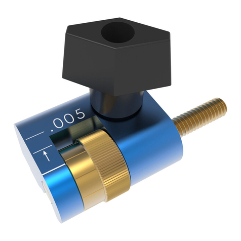
Séparez la plaquette protectrice en plastique de sa pellicule protectrice. Puis, centrez la
plaquette et collez-la soigneusement sur la base du Bench Klamp™. À l’aide d’une paire de
ciseaux, coupez, le cas échéant, tout excédent de plaquette qui dépasse de la base du Bench
Klamp. Insérez ensuite la vis d’ancrage dans la base du Bench Klamp™. Commencez par
insérer la vis d’ancrage jusqu’à la moitié, puis essayez de la glisser dans la plaque Klamp
Vise™. Si l’assemblage est trop serré, le Bench Klamp™ ne glissera pas librement sur le rail.
Si, par contre, l’assemblage n’est pas assez serré, le serre-joint pourrait se coincer pendant
que vous le faites glisser sur le rail.
Installation du serre-joint • Instalación de la abrazadera
Installation du valet d’établi • Instalación del perro de banco
Klamp Blocks • Klamp Blocks
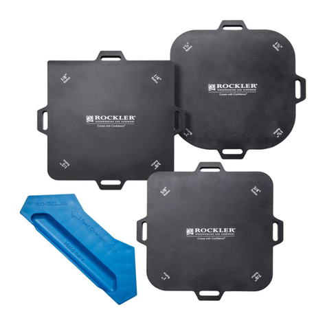
Los Klamp Blocks™ se diseñaron para ayudarle a obtener la altura correcta de la pieza de trabajo
cuando utiliza la Klamp Vise™ para aplicaciones de tipo prensa de tornillo tradicional donde la pieza
de trabajo está en posición vertical. Hay 4 dimensiones que aparecen en cada Klamp Block™
(3,81 cm, 5,08 cm, 6,35 cm, 7,62 cm) relacionadas con la distancia entre los bordes del Klamp
Block™ y el punto central donde el Bench Klamp™ hace contacto con la pieza de trabajo.
Después de que ha elegido el ajuste del Klamp Block™, inserte el perno en T en la lengüeta de
alineación opuesta a la marca (como se muestra en la imagen para ajuste de 3,81 cm) y fíjelo en el
lugar con una tuerca de plástico.
French Français • Spanish Español
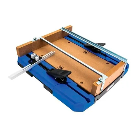
Hay una amplia variedad de aplicaciones prácticas para el Klamp Vise™. Las puede utilizar
en aplicaciones de tipo de prensa de tornillo tradicional, en sujeciones verticales y horizontales
para piezas de trabajo grandes y pequeñas. Pruebe el Klamp Vise™ en conjunto con otros
componentes Klamp System™ (incluye el Klamp Plate™, Klamp Trak™, Large Bench Klamp™,
entre otros) para obtener la mejor solución de sujeción posible.
Separe la almohadilla plástica de deslizamiento del protector de papel. Luego, centre y
adhiera cuidadosamente la almohadilla a la base del Bench Klamp™. Cualquier parte de
la almohadilla que sobresalga de la base del Bench Klamp se puede recortar con un par
de tijeras. Luego, inserte el tornillo de anclaje en la base del Bench KlampTM. Comience
ajustando el tornillo de anclaje aproximadamente hasta la mitad y pruébela en la placa
Klamp Vise™. Si la conexión está demasiado ajustada, el Bench Klamp™ no podrá moverse
libremente a través del riel. Si la conexión está demasiado suelta, la abrazadera se puede
enganchar mientras la desliza por el riel.
Le Klamp Vise™ peut être utilisé de plusieurs manières différentes. Il peut être utilisé comme un
étau traditionnel, pour le serrage à la verticale et à l’horizontale, ainsi que pour les pièces de grand
ou de petit format. Utilisez le Klamp Vise™ conjointement avec d’autres composantes du Klamp
System™ (comme la Klamp Plate™, le Klamp Trak™, le Large Bench Klamp™, etc.) pour obtenir
la meilleure solution de serrage possible.
Les Klamp Blocks™ sont conçus pour vous aider à obtenir la bonne hauteur de pièce lorsque
vous utilisez le Klamp Vise™ de la manière habituelle, alors que la pièce est en position
verticale. Quatre dimensions sont inscrites sur chaque Klamp Block™ (1 1/2 po, 2 po, 2 1/2 po et
3 po). Ces dernières indiquent la distance entre le bord du Klamp Block™ et le point de contact
central entre le Bench Klamp™ et la pièce.
Après avoir déterminé la position du Klamp Block™, insérez le boulon pour rainure en T dans la
patte d’alignement opposée à l’indication (un réglage de 1 1/2 po est illustré) et xez-le en place
à l’aide de l’écrou en plastique.
1. 2.
19,10 mm
Bois Métal
Madera Metal
Fonctions • Usos
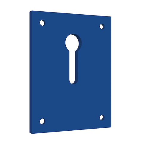
Déterminez l’endroit où vous souhaitez installer la plaque Klamp Vise™. L’établi ou la pièce
doivent avoir une épaisseur d’au moins 2,54 cm et d’au plus (sans modication) 5,08 cm. Ils
doivent être sufsamment robustes pour supporter une pression de serrage importante. Pour
xer la plaque, utilisez des vis cruciformes à tête cylindrique de 1 po 1/4-20 pour les surfaces
en métal et des vis à bois cruciformes no14 x 1-1/2 pour les surfaces en bois.
Les valets d’établi Kreg sont faciles à utiliser, et encore plus à
installer. Ils conviennent à n’importe quel trou pour valet d’établi
de 3/4 po. Si votre établi ne comprend pas de trous pour valet
d’établi, percez-en à l’aide de forets à bois à trois pointes ou
d’avant-clous de 3/4 po. L’emplacement des trous sera différent
selon la taille des différentes pièces. Vous pouvez aussi xer les
Bench Brakes™ (facultatifs) sur le dessus des valets d’établi. Ces
pièces de caoutchouc toutes simples vous permettent d’effectuer
vos travaux de ponçage, de toupillage et de sciage sur une
surface solide et antidérapante.
Ubique el lugar en donde le gustaría conectar la Placa Klamp Vise™. El banco de trabajo y la
pieza de trabajo deben tener al menos 2,54 cm de grosor y un máximo de 5,08 cm de grosor
(sin modicaciones). Debe ser sucientemente resistente para soportar una fuerza de sujeción
considerable. Utilice 20 tornillos de cabeza Phillips de 1 ¼” para supercies metálicas o
tornillos Phillips para supercies de madera de #14 x 1-1/2 para jar la placa en su lugar.
Los perros de banco Kreg son fáciles de utilizar e incluso más
fáciles de instalar. Se adaptan a cualquier oricio de perro
existente de 19,10 mm del banco de trabajo. Si su banco no
posee oricios para perros de banco, utilice una broca de madera
o una broca de tres puntas de ¾” y taladre uno. La ubicación de
los oricios debe variar para ajustarse a una variedad de tamaños
de piezas de trabajo. También puede jar los Bench Brakes™
opcionales en la parte superior de los perros de banco. Estas
simples piezas de goma le darán una supercie de trabajo sólida
y antideslizante para lijar, rebajar y aserrar.
3/4 po
