Krill Avanti S jet 2.1m ARF User manual

The all new sport/3d jet is a masterpiece!! Designed by Italy’s Sebastiano Silvestri. Its
design is based on a hawk aircraft. And then been improved further with aerodynamic
ideas learned on other pattern models.it is a very lightweight and strong construction.
This helps, as the flight speed rang is really impressive!! Designed to take an engine with
100n of thrust, it is setup to be an ideal jet trainer BUT with a 220-250n turbine you have
the ultimate 3d jet!!
This will let you into a totally different flying experience!!
Krill Avanti S jet 2.1m ARF
Assembly manual.
Specification: setup range of installation:
Wingspan:…2.1m Turbine:…..from 100n to 250n
Length:….2.22m radio:…..9-12 channel radio system
Weight: RTF dry (p100)…10.5kg servos:8 digital, metal gear servos.
1.

Required Radio, batteries and turbine
Radio equipment:
•Digital servo:5 JR ds8411 (ailerons, elevators, nose steering
3 JR ds8911 (flaps and rudder)
(2 JR ds 8915(vectoring thrust-optional)
•For pneumatic landing gear operation: one dual air valve (not included)
•For pneumatic brake operation :one single air valve(not included)
•Powerbox systems range from:
Sports setup: powerbox champion or powerbox royal.
3d setup: powerbox royal or powerbox cockpit + igyro
•We recommend using a powerbox smoke pump
•RX Batteries can be from 2500-3500mah-2s lipo
Recommended turbines:
•For Jet beginners:p100
•For FAI F3S aerobatics:140n to 160n
•For 3d unlimited flight:180n-250n (vectored thrust pipe optional)
Recommended tank:
•Sebart tank for kero +UAT+Smoke (optional with kit)
•3d setup users with 180n or more. The fuel systems must have a high flow system. The
recommended tank will not produce the amount of fuel these big engines are required .There for
the standard tank design is not recommended.
BISHOP AVIATION: CMJETS 5.6l fuel tank only. Used with a high flow composite fuel trap.
2.

Wing Assembly (Aileron servo JR ds8411.)
Aileron rod length and horn position (note Aileron horn is 5mm back from wing skin, set
with zero aileron deflection).
Aileron linkage length is 110mm from ball to servo horn.
3.

Wing Assembly (Flap servo JR ds8411. horn and rod position)
(Note Flap horn is 10mm from flap hinge line).
Flap rod length is 80mm long from ball to servo horn.
4.

Wing Assembly (door/leg and front dowel modification )
Door assembly
After fitting the retract into the pre-moulded cut outs in the wing. Make sure the leg retracts with room to spar and
is not touching wheel well skin. Now it is time to slide the top door fixing though the leg when it is removed. Refit leg to the
retract and align the wheel parallel to the wing root face. Retract the leg and make sure it is completely locked. Now slide
the half round second door fixing 10mm out from the leg base.(sand if necessary).now place door over the moulded slot
and make sure that there is a 1mm gap round the outside of the door to allow for movement in flight.(note door shape has
to be significantly shaved down to clear leg upon suspension). After you are satisfied that the door sits flush with wing
skin, you can now epoxy the door to the fixings. After cleaning and etching place epoxy on the top faces of the two
mounting blocks and place door in the correct position. Apply tape if necessary to hold in place.
After glue is dry remover leg from retract and care fly slide door out of the leg. Apply more epoxy if required.at this
stage you can paint the door if want to. Now etch all remaining surfaces that is left to be glued and then apply to the leg
and inside of the door fixings. Slide door assembly into the leg and reassemble leg to the retract. Making sure leg is fully
retracted and locked. Hold firmly until epoxy is dry. Repeat these stages on wing number 2.
5.

Wing assembly (wires and air tubing)
Front dowel modification
After fitting and fixing the wing half’s to the Fuselage. You may find there is some rear movement when
wing is Pulled back. This can cause the flap to touch the fuselage wing face.Replacing a 6mm thread to the front
dowel which is held in place with a thumb screw, will make sure that in flight.The wing will not move and lock the
flap up in flight.
Wires and air tubes can be rooted through the small tube that is installed at the front of the flap servo mounts.
The flap wire is rooted through this tube and across the retract bay and then though to the front of the wing
root.
6.

Tail stab Assembly
Install the JR ds8411 into the stab half with the servo horn set with horn facing to the front of the tail half. Make
sure you thread servo wire through the small hole before slotting in the servo.
Length of the push rod in 94mm from ball to servo horn.
Elevator horns are set 5mm back from the tail skin. This will make the hinge line and horn pivot in line at zero
deflection.
7.

Rudder Assembly
Rudder hinges are factory finished and require no attention but it is good practice to check glue joints and
movement.
First install the JR ds8511/8911 into the pre-cut hatch on the side of the fin. Servo mount is located on the top of
the hatch and will be easier to install with the plane inverted. Make sure the servo wire in pushed thought the
small pre-cut hole in the servo mount. Fit a metal JR 3d horn onto the servo and cut out a slot which is 90% of
the hatch length. Centre servo then drill a 1.5mm hole in the middle of the second and third hole to take a clevis.
And trim remaining horn off. As Seen below.
Rod length is 92mm from ball to servo hole.
Rudder double horn is positioned 5mm back from fin skin with zero deflection on rudder. Cut rudder horns
parallel to the servo movement to inshore there is no fouling.
8.

Fuselage Assembly
Front doors
The front doors are ready hinged from the factory and just require a horn and servo
install to complete.
First select the two horns provided in the bag of horns. They require 10mm
reduction to clear the nose leg upon retraction.
Install the midi servos as shown in the picture above. Now setup a 2mm threaded rod and ball
link system to the servo horn. Also fit a 2mm clamp fitting to the door horns. This setup makes
travel adjustment easier later. Slide 2mm rod through the door horns and tighten clamp with the
servo horn down at a 45 degree angle and also door fully open. Door horn should be 5mm away
from hinge line of the doors. After making sure the rod and horns are perfectly in line you can
tack with C.A and then manually check operation. When you are happy, you can epoxy horn
joints for a permanent fixing.
Installing the nose leg retract is easy. Just make sure that the retract sits completely on the
plywood plate, without it distorting the retract unit.
(Note after completing the front door. Make sure the doors close without too much strain to
the servos. Sand if necessary).
9.

Fuselage Assembly (pipe fixing)
(Make sure you have selected the correct pipe for your engine size)
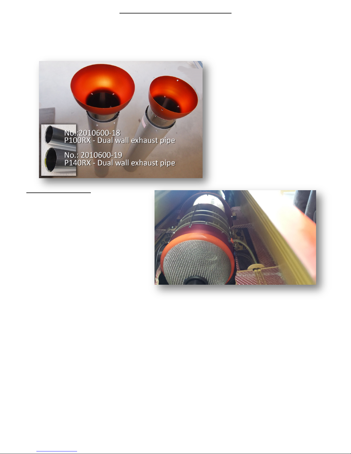
As shown below there are two types of pipes for the JetCat p100RX and the p140RX.If you are not using JetCat
Turbines then you just need to look at the thrust (N) which corresponds to your engine and the JetCat turbines.
p100RX =100N of thrust
p140RX=140N of thrust
Installing the pipe
Test fit the pipe in your Avanti.
It should be a perfect fit at the Back former.
And also sit snug in-between the turbine mount
formers at the front. The pipe should sit level to
the fuselage skin at the back, for ideal airflow
around the pipe. Mark where the front of the
bell meats the formers, then remove pipe.
Use the single hardwood block supplied for the pipe mounts. Cut block in half and drill a 1.5mm hole 5mm in on
both blocks. Then screw blocks to each side of the predrilled holes in the bell mouth. Now slide the pipe in and
line up the front marks to the front of the bell. (Note the pre-drilled holes on the bell are offset and must be
checked that the bigger radius is at the bottom mark with a pen for ease to eliminate mistakes).At this stage
you can trial fit your engine to see if it is centred by looking through the back of the pipe. If it is not then there
are two things you can try.one is turn engine mount 180 degrees and the other is to place blocks under the
engine mount until centred. (Note engine blocks in the kit are required for strength on the engine mount and
need to be taken into account).After making sure pipe is in line with the turbine you can epoxy the hardwood
blocks.by sliding the pipe forward and applying glue to the engine formers that they sits on. After they are
completely dry remove the pipe.
10.

Elevator and Rudder extension leads
After fitting the pipe it is time to start from the back of the Avanti, completing jobs through to the front.
(Always use high quality extension leads to handle any power loss in the long wire)
Use 3 1000mm extension lead for the elevators and rudder. Route cables round the back internal former and
down into the nice long groove and the bottom of the fuselage. Hold in place with cable tie. You can also sleeve
with heat resistant lagging if you want to. Also added protection, you can use 1/16 balsa sheet on the bottom of
the fuselage to completely seal the wires on the bottom. After making sure all wires are as far away from the
pipe as possible you can screw the pipe in and the back of the Avanti is complete.
11.

Aileron and flap wire install
It is easier and safer to use PowerBox dual servo wire, multiplex leads for the wing join. As it is only one
connection and makes for even quicker rigging at the field. These wires are rooted though the front half of the
wing face and under the intakes and down the middle trench. This makes them invisible from the intakes at the
front.
12.

Airlines and retract valve.
Airlines are rooted through the hole
behind the wheel well, and joined in the middle
with t-pieces .there are many ways to install the
radio and valves in jets. But we think that this
way will save weight and look neater if the
retract valve is placed and in the middle of the
wheel wells. We use a manual all in one brake
and retract valve to save weight and
complicated plumbing. But dual air and brake
valves are fine to use also. And can be placed
at the front of the jet if proffered. However
you choose to Install the valves all airlines are
best rooted through the middle trench of the
fuselage to ensure 90 present of the wires are
not in the airflow through the intakes.
13.

Turbine mounting plates and smoke tube.
Supplied in the kit are four mounting plates for your engine. These are necessary to
give the mounting formers the extra strength it requires.
Mounting the engine is one of the hardest jobs building the Avanti so should not be
rushed.
First make sure your tail pipe is installed and screwed. Now assemble your engine
mount so the burner element is towards the top. (You can rotate engine20-30
degrees each way so fuel and kero pipes are one side and wires are the other.)This
will make install easer later. Now place the two plywood plates on top of the turbine
formers and place engine on top of them. Now see if the engine cone is in the
middle of the pipe looking down the rear of it. If turbine is to low then you can
simply add extra peaces of plywood until you are happy your engine in centred.
Fixing Turbine Mounting Plates.
(Before fixing engine plates make sure you know the correct distance from your
turbine tail cone to the start of the pipe).here is a little guideline to follow.
(Measurements are with a 60mm bell length)
(Note red arrows are where all measurements need to be worked from).
14.

Turbine mounting plates and smoke tube.
Epoxy mounting plates and hold in place with plates, top and bottom of the mounting formers as seen above.
Now slide engine in the correct possession for your engine. Making sure the turbine is centred in all direction,
mark the holes in the metal turbine mount on the plywood mounts. Remove turbine and had drill or using a 90
degree Dremel attachment drill all the holes. Use 1.5mm holes if you decide to screw your engine in with wood
screws. Or you can drill holes with a 4mm bit to take 4mm bolts. Remove turbine and now use a 6mm drill bit to
take claw nuts from the bottom of the mounts. This is not easy but take your time your nearly there!!
now screw engine in and re check alignment.
Smoke tube and smoke pump position
Using a single smoke tube in fine and still makes a great effect in the air. Bend 4mm brass tubing so it is going
across the centre of the turbine cone and ends in the middle of it. Flatten the end of the brass tubing so it is
uniform and just wide enough to take a knife blade through the flattened end.(make sure the flattened end in is
vertical to the plane to produce maximum fan over the engine efflux).Fix with steal or aluminium sheet bent
round the tubing and clamped with screws.A 4mm to 4mm fiesto will connect on the brass tubing and to fuel
tubing the other side.
15.

fuel tank and U.A.T.
If you are using a turbine
with 140N or lower, the
recommended fuel tank from
krill is ideal. And offers a
complete unit for fuel, smoke
and air trap combined into a
nice single unit that fits
great in the space available.
however if your intending to
install a 180N or higher
turbine we recommend using
a single large fuel cell as seen
on the right.by CM jets.
To install the tank, all that’s needed is to use the plywood tank mounts supplied. Screw the tank
in with 4mm claw nuts and bolts provided making sure they are centred and have an equal gap
either side. Remove mounting plates from the tank and glue and screw with hysol. The front
fixing on to the rear face of the centre former, under the turbine mounting rails as shown below.
Now screw front mounting to the tank. Slide the rear plate
under the tanks fixing also under
the turbine mounting formers and
screw together. Now screw the
plate to the former. When this is
done you can remover tank and rear
plate for gluing and then reinstall using
the screws you fixed it in with earlier.
vent tubes run down and through the formers and into one placed either side next to the
intakes. 16.

Radio install
There are many ways to install a jet turbine. But the most important thing is the fuel lines before
the pump are as short as possible. Also depending on the c of g. With these factors taken into
account, here are some ideas of installation. we recommend leaving the battery install till the
very end when you are setting up the c of g. (Note air tanks are placed under the front board and
are joined together for one air system)
(Note these pictures are with a 3d setup and Jet Italia 220N lion. They are only guidelines and
may change with different radio and turbines.
17.

Mods,extras and 3d setup
Smoke tank and smoke pump.
When using a single fuel cell where does the smoke pump go? There is plenty of
room to fit a 40oz (1200cc) tank under the main fuel cell. You can even fit a 52oz
tank in there as well. Fixed in place with 2 rails either side and Velcro straps.
Smoke pump is best mounted under the board on the front tank former. This is best
as the tubing and wires are all in the right area for plumbing.
Smoke pump Smoke vent next to the fuel vents.
18.

3d vector thrust pipe and install.
Vectored thrust pipes are also an option when ordering your Avanti from krill Models.
(Installing the thrust pipe for vectored thrust is quite simple but you must take care with aligning
the two pivots 90 degrees to the plane).
Fix pipe with the bell the same way as shown earlier. However the outer wall of the pipe can
rotate and be pushed in.This will change the alignment of the vector centre points.so what needs
to be added, is a rear bracket that will anchor the outer pipe. Here are some pics that will show
you the shape and location of this bracket.
There is a nut that is holding the rudder vector pivot in place which can double as a holding peg
for the bracket. When fabricating the bracket make shore the two pivots are 90 degrees to the
plane. Also the outer wall of the pipe is pulled fully back on the front tab. that holds the outer
together.
19.

3D vector thrust pipe servo and push rod install.
To get best results from gyro assessed vectored thrust it is very important to have
high speed and high power servos. As the gyro often can try and work quicker than
the servo can operate. This causes delay and catch up with the servo. This can
result in the gyro not working properly or possibly uncontrollable!!
The recommended servo is the JR ds8915 ultra high speed digital servo.
Also using the JR metal 3d horns. As used on the rudder.
(Note rudder vectored servo arm needs to be
(Reduced to the second hole from the middle).
Elevator servo arm is only reduced by one hole).
20.
Table of contents
Other Krill Toy manuals
Popular Toy manuals by other brands

KNEX
KNEX 17023 manual

4max
4max Inspiration F3A 50E Assembly instructions

Carson
Carson POLICE TYRANN 230 GYRO 2.4 GHz instruction manual

V-tech
V-tech Little Apps Tablet user manual

Radica Games
Radica Games PASSWORD PUPPIES G71026 instruction manual

Hasbro
Hasbro NERF Power Moves Marvel Black Widow instructions

Faller
Faller 180664 manual

Extreme Flight
Extreme Flight 110" YAK-54 V2 Assembly manual

Agora Models
Agora Models Mitsubishi A6M ZERO Fighter Build instructions

Kyosho
Kyosho EP JETSTREAM888 VE instruction manual

Pro Boat
Pro Boat Miss Budweiser owner's manual

SIG
SIG Piper J3 Cub Assembly instructions/use and care manual