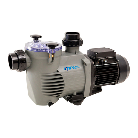
Kripsol KNG User guide

MANUAL DE INSTRUCCIONES PARA EL USO Y
MANTENIMIENTO
de las Electrobombas de Piscinas.
HANDBOOK FOR USE AND MAINTENANCE
of Electropumps for Swimming Pools.
MANUEL D´INSTRUCTIONS POUR L´UTILISATION ET
L´ENTRETIEN
des Electropompes de Piscines.
BETRIEBS-UND WARTUNGSANWEISUNG
für die Schwimmbad-Elektropumpen.
MANUALE D´ISTRUZIONI PER L´UTILIZZO E LA
MANUTENZIONE
delle Elettropompe per Piscina.
Tipo / Type / Type / Modell / Tipo: KNG
Bomba NIAGARA:Bomba NIAGARA.qxd 27/01/2010 18:01 Página 1

Bomba NIAGARA:Bomba NIAGARA.qxd 27/01/2010 18:01 Página 2

1.1 Estas electrobombas han sido
diseñadas para efectuar la recirculación
de aguas ligeramente tratadas en
piscinas y spas, privadas y públicas.
1.2 CARACTERÍSTICAS TÉCNICAS.
Motor:
Potencia :
Ver placa de electrobomba.
Aislamiento: Clase F.
Servicio : Continuo.
Protección : IP 54.
Tensión
: Monofásica y trifásica (ver
placa de características).
Consumo
: Ver placa de características.
Frecuencia
: Ver placa de características.
R.P.M.
: Ver placa de características.
Eje : Acero inoxidable.
Cojinete : Rodamiento de bolas
blindado.
Temperatura ambiente: Máximo 40ºC.
Bomba:
Temperatura agua:
Máximo 50ºC.
Presión máxima : 2 bar.
Modelo turbina : Cerrada.
Tipo de sello : Retén mecánico.
Difusor y turbina
: Tipo KS, material
sintético (PPO).
Cuerpo de bomba
: Tipo KS, material
sintético (PPO).
Diámetro aspiración :
ø50-ø63 (encolar).
Diámetro impulsión :
ø50-ø63 (encolar).
2.0 INTRODUCCIÓN
Este manual contiene las instrucciones
necesarias para la instalación, el uso y
el mantenimiento de la electrobomba
de piscinas.
Para obtener de ella las prestaciones
que el fabricante indica en las Hojas de
Características, es necesario que se
cumplan y sigan correctamente todas
las recomendaciones dadas en este
Manual. Esto permitirá trabajar con un
equipo seguro y duradero.
El proveedor del equipo facilitará al
usuario información complementaria, si
éste la requiere.
2.1 SIGNOS DE SEGURIDAD EN EL
MANUAL DE INSTRUCCIONES.
Aquellas instrucciones que se refieren
a los riesgos para las personas, se
destacan con los dos símbolos
siguientes:
Otras instrucciones que estén
relacionadas con el funcionamiento del
equipo y cuya falta de cumplimiento
pueda dañarlo fisicamente, se destacan
con la inscripción:
2. GENERALIDADES
ESPAÑOL
1. DESCRIPCIÓN
3
ATENCIÓN
Precaución por
peligro en
general
Precaución por
peligro descarga
eléctrica
Norma DIN
4844-W9
Norma DIN
4844-W8
Bomba NIAGARA:Bomba NIAGARA.qxd 27/01/2010 18:01 Página 3

2.2 PLACAS DE CARACTERÍSTICAS
(de CEE 89/392 p.1.7.4.a).
Lo que se indique en la placa de
características u otras instrucciones que
el fabricante coloque sobre la unidad,
se observarán en este Manual
(Capítulo 1.2.).
2.3 RESPONSABILIDAD.
El no cumplimiento de las instrucciones
dadas por el fabricante en este Manual,
para la elección, manejo, instalación,
puesta en marcha y mantenimiento de
la unidad, libera al fabricante o distribuidor
de responsabilidades por accidentes
posibles a las personas o daños causados
al resto de las instalaciones,
ocasionando, además, la pérdida de la
garantía.
2.4 NORMAS.
Las electrobombas de nuestra marca
están fabricadas de acuerdo con los
requisitos esenciales de seguridad y
salud establecidas en las Directivas
Comunitarias 98/37/CE.
3.1
Sólo se podrá garantizar la seguridad
del servicio de la máquina suministrada
si su uso corresponde a lo indicado en
los esquemas de la página 38
“ILUSTRACIONES”. Nunca se deberán
sobrepasar las condiciones y límites de
trabajo indicados en este manual (capítulo
1.2 - Características Técnicas), asi
como las propias de la tarjeta de
características eléctricas indicadas en
la bomba. Es obligatorio cumplir con lo
legislado por las Normas de Seguridad
vigentes en cada país.
3.2
Asegurarse que el equipo se ha
seleccionado adecuadamente a la
aplicación a la que va destinado y que
su estado, instalación, puesta en marcha
y posterior uso sean correctos. Ver
capítulo 1 (Características Técnicas).
3.3
Las operaciones de instalación,
reparación y mantenimiento se harán
siempre con el equipo desconectado
de la red de alimentación eléctrica.
3.4
Mientras el equipo esté en
funcionamiento no puede ser
desplazado, ni corregida su posición.
Estas operaciones se harán siempre a
máquina parada.
3.5
El accionamiento de los elementos
eléctricos de conexión-desconexión o
seguridad no puede hacerse con
presencia de humedad, poniendo
especial cuidado en la que pueda existir
en las manos del operario, en su calzado
o superficies de contacto.
3. INSTRUCCIONES GENERALES
RELATIVAS A SEGURIDAD DEL
USUARIO
4
Bomba NIAGARA:Bomba NIAGARA.qxd 27/01/2010 18:01 Página 4

3.6
Los elementos del equipo que durante
su funcionamiento estén en movimiento
o puedan alcanzar temperaturas
peligrosas, se protegerán con rejillas o
carcasas que impidan el contacto
accidental con ellos.
3.7
Los conductores eléctricos, o partes
que puedan estar bajo tensión, dispondrán
del aislamiento adecuado. Otras
partes metálicas del equipo se unirán
solidariamente a tierra.
3.8
Los repuestos necesarios serán los
originales del fabricante o los recomendados
por él. El uso de otros, o de originales
rectificados por terceros no están
permitidos y exhimen al fabricante o
distribuidor de sus responsabilidades.
4.1
El fabricante suministra el equipo
protegido con el embalaje adecuado,
para que al transportarlo o almacenarlo
no sufra daños que impidan su correcta
instalación y/o funcionamiento.
4.2
El usuario, a la recepción del equipo,
comprobará inicialmente estos puntos:
-
Estado de embalaje exterior; si presenta
signos de deterioros importantes, lo
hará constar formalmente a quien se lo
entrega.
- Verificará también el estado del
contenido; y si éste presentase
desperfectos que presumiblemente
impidiesen su correcto funcionamiento,
lo comunicará, también formalmente, al
proveedor en un plazo máximo de 8
días desde el de la recepción.
4.3
Las condiciones de almacenamiento
serán tales que garanticen el buen
estado de conservación del equipo.
Señalamos por su especial importancia
las de evitar ambientes de humedad
acusada u otros donde puedan producirse
cambios bruscos de temperaturas
(producen condensaciones).
5.1. EMPLAZAMIENTO.
El lugar de instalación de la motobomba
tiene que ser seco. En cualquier caso
debe existir un desagüe en el suelo
como protección contra inundaciones.
Si se monta la bomba en un local
húmedo, habrá que prever un sistema
de ventilación para evitar la formación
de agua de condensación. En el caso
4. EMBALAJE, TRANSPORTE Y
ALMACENAMIENTO
5
ATENCIÓN
ATENCIÓN
ATENCIÓN
5. INSTALACIÓN Y MONTAJE
ATENCIÓN
Bomba NIAGARA:Bomba NIAGARA.qxd 27/01/2010 18:01 Página 5

de montajes en espacios muy
reducidos, el enfriamiento del aire
puede ser tan bajo que sea necesario
un sistema de aireación y desaireación
(ventilación) con el fin de no exceder la
temperatura ambiente de 40ºC.
Es importante que la reserva de
espacio sea suficiente para poder
desmontar el bloque motor en sentido
horizontal (véase dibujo de espacio
mínimo en fig. 1, pág. 38).
5.2. LOCALIZACIÓN / INSTALACIÓN.
El equipo o conjunto del grupo
motobomba, filtro y válvula selectora,
se instalará cerca de la piscina a una
distancia no superior a 3 m. de las
tomas de superficie (skimmer-
rebosadero) y preferentemente a una
cota de 0,5 m. (nunca superior a 3 m.)
bajo el nivel del agua, para conseguir
su funcionamiento “en carga”. La unión
de las boquillas y demás accesorios
empotrados en la piscina se realizará
prioritariamente en tubería de PVC.
El diámetro de las tuberías dependerá
de los caudales. La velocidad máxima
aconsejable del agua en las tuberías ha
de ser de 1,2 m/s. en aspiración y 2
m/s. en el retorno. En cualquier caso, el
diámetro de la tubería de aspiración no
debe ser inferior al diámetro de la boca
de la bomba.
La tubería de aspiración debe ser
perfectamente estanca y se ha de
instalar con una pendiente descendente
(no inferior a 1/100), evitando de este
modo la formación de bolsas de aire.
La tubería de aspiración puede ser
rígida o flexible con espiral de refuerzo
que evite la contracción.
En instalaciones fijas, con la bomba por
debajo del nivel del agua, se colocará
una válvula de cierre en aspiración y
otra en impulsión.
Para su utilización como bomba fijada a
un dispositivo móvil (durante el
movimiento del dispositivo móvil la
bomba debe permanecer fija),
prever
una adecuada protección eléctrica
y
montar la bomba sobre una base aislante.
5.3. CONEXIÓN ELÉCTRICA.
- Con carácter general, la instalación
eléctrica estará, en todo, de acuerdo
con lo prescrito en los Reglamentos y
disposiciones Técnicas Complementarias
que sean de aplicación y lo hará un
Instalador autorizado.
- La red de alimentación dispondrá de
conductores de neutro y tierra.
- La tensión de la red tiene que
corresponder con la dada en la placa
de características del equipo.
- La selección de los conductores a utilizar
tiene que ser suficiente para soportar,
sin deterioro, la intensidad absorbida
por el equipo (ver placa de características).
- Al conductor de tierra de la red se
unirán eléctricamente todas las partes
metálicas del equipo que no deben
estar bajo tensión, pero que
accidentalmente pudieran llegar a
estarlo y sean accesibles a las
personas (ver figs. 2 - 4, y págs. 38 - 39).
6
ATENCIÓN
ATENCIÓN
ATENCIÓN
Bomba NIAGARA:Bomba NIAGARA.qxd 27/01/2010 18:01 Página 6

- Es obligatoria la instalación de un
cuadro eléctrico de protección y
maniobra en el que se sitúan todos los
elementos exigidos y otros recomendados.
Con carácter general dispondrá de:
a) Interruptor general de corte unipolar.
b) Dispositivos de protección contra
cortacircuitos y sobrecargas en los
motores.
c) Interruptor diferencial de alta
sensibilidad, 30 m.A.
d) Otros, de mando y control.
Las características eléctricas de los
dispositivos de protección y su
regulación, estarán de acuerdo con las
de los motores a proteger y con las
condiciones de servicio previstas para
éstos, y se seguirán las instrucciones
dadas por el fabricante (ver placa de
características).
- En equipos con motores trifásicos hay
que posicionar adecuadamente los
puentes de interconexiones de los
devanados del motor (ver figs. 3 - 4,
págs. 39).
- La entrada y salida de conductores a
la caja de bornas se hará mediante
prensaestopas que garantizan la
ausencia de humedad y suciedad en
ésta, por lo que estará provista de un
cierre estanco.
- Los conductores, para su unión a
bornas, estarán dotados de terminales
adecuados.
6.0. Antes de poner el equipo bajo
tensión, conectado a la red, se harán
las siguientes operaciones:
- Verificar que las condiciones
eléctricas sean correctas.
- Comprobar, manualmente, que la
motobomba no está agarrotada.
6.1. CEBADO DE BOMBA.
Con la bomba por debajo del nivel
del agua de la piscina, llenar la bomba
abriendo lentamente la válvula
de cierre
de aspiración, teniendo abierta
la
válvula situada en su impulsión.
6.2. SENTIDO DE GIRO.
Asegurarse que el eje del motor gira
libremente: no poner en marcha si
está bloqueado. Para este fin, las
electrobombas tienen una ranura en el
extremo del eje, lado ventilador, que
permite hacerlo girar a mano con un
destornillador.
En los motores trifásicos la turbina (16)
puede destornillarse si el motor arranca
en sentido contrario. La rotación
inversa puede también incluso dañar el
sello mecánico.
Arrancar pocos segundos el motor y
controlar que el sentido de rotación
corresponde al indicado en la flecha
situada en la tapa del ventilador. Si no
fuera así, es imprescindible avisar a un
instalador autorizado (invertir la
conexión de fases entre ellas).
7
6. PUESTA EN MARCHA
ATENCIÓN
ATENCIÓN
Bomba NIAGARA:Bomba NIAGARA.qxd 27/01/2010 18:01 Página 7

6.3.
Comprobar que el motor no supera el
amperaje indicado en la placa de
características (36) (fig. 5, pág. 42); en
caso contrario regular con la válvula
situada en impulsión.
Evitaremos el funcionamiento prolongado
de la electrobomba: descebada, con la
válvula cerrada o por falta de agua en
aspiración.
Antes de cualquier manipulación,
desconectar la alimentación eléctrica.
7.1.
Si la bomba permanece parada por
periódos largos, o si existiese peligro
de heladas, se debe vaciar el cuerpo
hidraulico (7) (pág.42), soltando el
tapón (10) de vaciado con su junta
tórica (8).
Antes de poner en marcha la bomba,
colocar el tapón (10) con su tórica (8).
Llenar de agua el cuerpo de bomba y
comprobar con un destornillador que el
motor no está bloqueado.
Si el eje
estuviese agarrotado, avisar a un
técnico cualificado.
En caso de inundación del motor, no
intentar ponerlo en marcha; se avisará a
un electrotécnico, y éste desmontará el
motor para proceder al secado del mism
o.
8.1.
Antes de cualquier operación, todas las
válvulas deben estar cerradas;
comprobado ésto procederemos a:
- Desconectar interruptor general
eléctrico e interruptor diferencial (a
realizar por especialista autorizado).
- Soltar y retirar los cables de
alimentación de la regleta de
conexiones (40), (fig. 5, pág. 42).
- Liberar los manguitos de aspiración y
retorno.
- Vaciar la bomba soltando el tapón (10)
con su tórica (8).
8.2.
Para desmontar y montar la electrobomba
ver plano de despiece (fig. 5).
Para extraer el motor del cuerpo hidráulico
(7), quitaremos los cuatro tornillos (21) y
apalancaremos con los destornilladores
colocando uno enfrente del otro.
Para desmontar la turbina (16),separaremos
el difusor
(14) y su junta (13),soltaremos
la tapa del ventilador (35) y quitaremos
8
ATENCIÓN
7. MANTENIMIENTO/CONSERVA
CION
ATENCIÓN
8. DESMONTAJE
ATENCIÓN
ATENCIÓN
Bomba NIAGARA:Bomba NIAGARA.qxd 27/01/2010 18:01 Página 8

el propio ventilador, bloquearemos el
eje del motor ayudandonos por una
mordaza, al tiempo que giramos a
izquierdas (inverso horario) la turbina
(16) con una llave de tubo nº 14; quedando
esta (16)
liberada del eje
. Junto al
impulsor (16) sale la parte móvil del
retén (17).
“Todas las piezas que vayamos a
acoplar deben estar limpias y en
perfectas condiciones de uso”
Para el montaje de la bomba
procederemos:
- Montar el sello mecánico (17/18),
(pág. 42), ensamblar la parte giratoria
del sello (17) sobre el saliente posterior
de la turbina (16) presionando ésta hasta
encajar en el alojamiento; previamente
habremos lubricado el retén con agua.
-
Ensamblar la turbina (16) en el eje (28)
fijando éste con Loctite o similar en el
inserto metálico roscado. De esta forma
se consigue la unión de las dos pistas
del sello mecánico (17/18).
- En la unión de la bomba con el motor
hemos de tener en cuenta que el resalte
del difusor (14) encaje en el alojamiento
adecuado, igualmente que las juntas
(13/19).
Para la solicitud de cualquier pieza de
recambio, precisar la denominación, el
número de posición en el plano de
despiece (fig.5, pág. 42) y los datos de
las placas de características (15 y 36).
9
9.
MONTAJE
ATENCIÓN
10.
RECAMBIOS
Bomba NIAGARA:Bomba NIAGARA.qxd 27/01/2010 18:01 Página 9

1.1 These electropumps have been
designed to recirculate lightly treated
water in swimming pools and spas, both
private and public
.
1.2
TECHNICAL CHARACTERISTICS.
Motor:
Power rating:
See nameplate ratings on
electropump.
Insulation : Class E.
Operation : Continuous.
Protection : IP 54.
Current
: Monophase and triphase
(see nameplate
ratings).
Consumption :
See nameplate ratings.
Frecuency
: See nameplate ratings.
R.P.M.
: See nameplate ratings.
Shaft : Stainless steel.
Bearing : Armoured ball bearing.
Atmospheric temperature:Maximum 40ºC.
Pump:
Water temperature :
Maximum 50ºC.
Maximum pressure: 2 bar.
Impeller model : Closed.
Type of seal
:Mechanical retainer.
Impeller & diffuser casing
:
Type KS, synthetic
material (PPO).
Pump casing
:
Type KS, synthetic
material (PP).
Aspiration diameter :
ø50-ø63 (socket).
Impelling diameter :
ø50-ø63 (socket).
2.0 INTRODUCTION
This Handbook contains the necessary
instructions for installation, use and
maintenance of the swimming pool
electropump. In order to obtain the
maximum yield shown by the
manufacturer in the Description of
Characteristics, it is necessary to
fulfil and follow correctly all the
recommendations given in this
Handbook.
This will allow operation with a safe and
long-lasting piece of equipment.
The equipment supplier will furnish the
user with complementary information, if
required.
2.1 SAFETY SIGNS USED IN THE
HANDBOOK.
All instructions referring to possible
risks to persons are highlighted by the
following symbols:
Other instructions in relation to the
functioning of the equipment with which
non-compliance could cause physical
damages are highlighted with the
warning:
2. GENERAL
ENGLISH
1. DESCRIPTION
10
ATTENTION
Danger in
general
Danger of
electrocution
Standard DIN
4844-W9
Standard DIN
4844-W8
Bomba NIAGARA:Bomba NIAGARA.qxd 27/01/2010 18:01 Página 10

2.2 NAMEPLATE RATINGS (EEC
89/392 P.1.7.4.A).
The information given on the nameplate
or other instructions affixed by the
manufacturer to the unit, must be
strictly complied with. The content of
these plates can usually be found in this
Handbook (Chapter 1.2.).
2.3 LIABILITY.
Failure to comply with the instructions
given by the manufacturer in this
Handbook, in relation to the choice,
handling, installation, starting and
maintenance of the unit, shall release
the manufacturer or distributor from all
liability in respect of accidents suffered
by persons or damages caused to other
installations and, in addition, shall entail
forfait of the warranty.
2.4 STANDARDS.
Our swimming pool electropumps are
manufactured in accordance with the
necessary requeriments
for safety and
health set forth in Community
Directives 98/37/EC.
3.1
Safety during operation of the
machinery supplied can only be
guaranteed if it is used in accordance
with the diagrams shown on page 38
“ILLUSTRATIONS”. It must never exceed
the working conditions and limits given
in this Handbook
(Chapter
1.2 -
Technical Characteristics).
Compliance with the provisions of
Safety Standards in force in each
country is mandatory.
3.2
Please ensure that the equipment
selected is adequate for the use for
which it is intended and that its condition,
installation, starting and subsequent
use are correct. See chapter 1
(Technical Characteristics).
3.3
Installation, repair and maintenance
operations will be carried out in all
cases with the equipment disconnected
from the mains.
3.4
While the equipment is functioning, it
cannot be moved or repositioned.
These operations will be carried out at
all times with the machine disconnected.
3.5
Pressing of the electrical on/off or
safety elements will not be performed
where there is damp, and special care
must be taken for user´s hands to be
dry, and also with footwear and
surfaces with which the user is in
contact.
3. GENERAL INSTRUCTIONS IN
RELATION TO USER SAFETY
11
Bomba NIAGARA:Bomba NIAGARA.qxd 27/01/2010 18:01 Página 11

3.6
Those elements of the equipment wich,
when functioning, are in movement or
which could reach dangerous temperatures
,
will be protected with cages or casing
which will prevent accidental contact
with the same.
3.7
Electricity conductors, or parts which
could carry current, will be suitably
insulated. Other metal parts of the
equipment will be correctly earthed.
3.8
Spare parts that may be necessary will
be originals from the manufacturer or
those recommended by the manufacturer.
The use of others, or originals rectified
by others, are not permitted and release
the manufactured of distributor from all
liability.
4.1
The manufactured supplies the equipment
protected in suitable packaging, so that
it is not damaged during transport or
storage thus preventing its correct
installation and/or functioning.
4.2
The user, upon receipt of the equipment,
will immediately check the following
points:
- Condition of the outside packaging, if
this shows sings of serious deterioration,
he shall formally advise the person
delivering the equipment.
- He shall also check the condition of
the contents; should this show defects
which would presumably prevent
correct functioning, he shall also formally
notify the supplier within a period not
exceeding 8 days from the date of delivey.
4.3
Storage conditions must ensure the
optimum preservation of the
equipment. Due to its particular
relevance, we must stress that very
damp atmospheres or others where
brusque changes in temperatures
(which cause condensation) must be
avoided
5.1. LOCATION.
The place where the electropump is to
be located must be dry. In all events,
there must be a drain in the floor as a
prevention against flooding. If the pump
is to be located in a damp place, a
ventilation system must be provided in
order to prevent the formation of
condensation.
4. PACKING, TRANSPORT AND
STORAGE
12
ATTENTION
ATTENTION
ATTENTION
5. INSTALLATION AND ASSEMBLY
ATTENTION
Bomba NIAGARA:Bomba NIAGARA.qxd 27/01/2010 18:01 Página 12

In the case of very confined areas, cold
air can reach a low temperature which
requires a ventilation system whereby
the atmospheric temperature does not
exceed 40ºC.
It is important for there to be sufficient
space to permit the motor block to be
dismounted horizontally (see minimum
space diagram in fig. 1, page. 38).
5.2. POSITIONING / INSTALLATION.
The equipment or set of motor pump,
filter and selection valve, will be
installed near the swimming pool at a
distance of no more than 3 m. from the
surface skimmers and preferably at a
level of 0.5 m. (never more than 3 m.)
below the level of the water, in order to
achieve its “under load” functioning.
The union of the nozzles and other
accessories incorporated in the
swimming pool will preferably be made
in PVC casing.
Pipe diameters will depend on flows.
The maximum water speed advisable in
the pipes will be 1,2 m/s. in aspiration
and 2 m/s. on return. In any event, the
diamenter of the aspiration pipe must
not be less than the diameter of the
pump nozzle.
The aspiration pipe must be perfectly
water-tight and must be installed with a
downward inclination, thus avoiding the
formation of air pockets.
The aspiration pipe can be either rigid
or flexible with a reinforced coil to avoid
contraction.
In fixed installations, with the pump
below the water level, a shut-off valve
will be placed on the aspiration pipe
and another on the header pipe.
When using as a pump fixed to a mobile
device (during the movement of the
mobile device the pump must remain
steady),suitable electrical protection
must be provided and the pump must
be assembled on an insulated base.
5.3. CONNECTION TO THE MAINS.
- In general terms, the electrical
installation will fully comply with the
Regulations and Complementary
Technical provisions applicable and will
be performed by an authorised Installer.
- The supply will have neutral and earth
wires.
- The mains voltage must correspond to
that shown on the nameplate rating for
the equipment.
- The earth wire to be used must be
sufficient to take, without deterioration,
the current absorbed by the equipment
(see nameplate).
- The mains earth wire will be
connected electrically to all metal parts
of the equipment which should not be
under current, but which could
accidentally be affected by the same
and which are accessible to persons
(see figs. 2 - 4, pages. 38 - 39).
It is obligatory to install a protection and
operation switchboard which will
contain all necessary and recommended
elements. Ingeneral terms, it will
contain:
a) General cut-off or unipolar switch.
b) Short-circuit and overload protection
devices for motors.
13
ATTENTION
ATTENTION
ATTENTION
Bomba NIAGARA:Bomba NIAGARA.qxd 27/01/2010 18:01 Página 13

c) 30 m.A. differential high sensitivity
switch.
d) Others for monitoring and control.
The electrical characteristics of the
protection devices and their regulation
will comply with those for the motors to
be prortected and with the service
conditions envisaged for these, and the
instructions given by the manufacturer
must be followed (see nameplate).
- In the case of equipment with triphase
motors, the motor winding interconnection
bridges must be suitably positioned
(see figs. 3 - 4, page 39).
- Conductor inlets and outlets at the
bushing box will have stuffings to
ensure the absence of damp and dirt,
and will therefore have a sealed casing.
- Conductors will have suitable
terminals for connection to the
bushings.
6.0. Before connecting the equipment
to the mains, the following operations
will be carried out:
- Check that the electrical conditions
are correct.
- Manually check that the motor pump is
not jammed.
6.1. PUMP PRIMING.
With the pump below the swimming
pool water level, fill the pump by slowly
opening the aspirations cut-off valve,
with the header valve in the open
position.
6.2. DIRECTION OF ROTATION.
Ensure that the motor shaft turns freely;
do not start the pump if it is blocked. For
this purpose, electropumps have a
groove at the end of the shaft, on the
ventilator side, which permits it to be
turned manually using a screwdriver
(fig. 1, page 38).
In triphase motors, the impeller (6) can
be unscrewed if the motors starts in the
opposite direction. Counter-rotation can
even damage the mechanical seal.
Start the motor for a few seconds and
check that the direction of rotation
coincides with that indicated by the
arrow on the ventilator cover. Should
this not be the case, it is absolutely
necessary to advise the authorised
installer (invert the phase connection).
6.3.
Check that the motor does not exceed
the amperage indicated on the
nameplate rating (36) (fig. 5, page 42);
otherwise, regulate using the header
valve.
14
6. STARTING
ATTENTION
ATTENTION
ATTENTION
Bomba NIAGARA:Bomba NIAGARA.qxd 27/01/2010 18:01 Página 14

Before touching, disconnect the
electricity supply.
7.1.
If the pump is switched off for long
periods of time, should there be a
danger of frost, the pump casing (7)
should be emptied, by loosening the
emptying outlet (10) along with its
O-ring seal (8).
Before starting the pump, replace the
outlet (10) and its O-ring seal (8).
Fill the pump chamber with water and
check with a screwdriver that the motor
is not
jammed. If the shaft
has seized up,
call a qualified technician.
In the event of the motor flooding, do
not try to start it; call an electrician to
dismount the motor in order to dry it.
8.1.
Before performing any operation, all
valves must be in the “off” position;
having checked this:
- Disconnect the general electricity
switch and the differential switch (this
must be done by an authorised specialist).
- Loosen and remove the supply cables
on the bushings box (40)
(fig. 5, page
42).
- Release the aspiration and return
sleeves.
- Empty the pump.
8.2.
In order to dismount and assemble the
electropump, please see the detail
drawing.
In order to remove the motor from the
hydraulic casing, remove the four
screws (21) and lever with two
screwdrivers, one opposite the other.
In order to dismount the impeller (16),
separate the diffuser (14) and its
junction (13), loosen the ventilator
cover (35) and remove the ventilator;
block the motor shaft with the aid of a
clamp, while rotating the impeller (16)
anticlockwise with a number 14 pipe
wrench, thus releasing the shaft (14).
The mobile part of the retainer (17)
comes out with the header.
“All parts to be assembled must be
15
7. MAINTENANCE/CONSERVA
TION
ATTENTION
8. DISMOUNTING
ATTENTION
ATTENTION
9.
ASSEMBLY
ATTENTION
Bomba NIAGARA:Bomba NIAGARA.qxd 27/01/2010 18:01 Página 15

clean and in perfect condition for use”
In order to assemble the pump:
- Assemble the mechanical seal
(17/18), (page 42), assemble the rotary
part of the seal (17) above the back
flange of the impeller (16) by pressing
until this falls into the space; the
retainer will have been lubricated with
water beforehand.
- Assemble the impeller (16) on the
shaft (25) affixing it withLoctite or
similar int the threaded metal insert. In
this way, the two grooves of the
mechanical seal are joined (17/18).
- At the junction of the pump with the
motor, it must be borne in mind that the
diffuser flange (14), and all other
connections (13/19), must fit into the
correct space.
To order any spare parts, indication
must be given of the denomination,
number shown on the detail drawing
(fig. 5 page 42) and nameplate ratings
(15 and 36).
16
10.
SPARE PARTS
Bomba NIAGARA:Bomba NIAGARA.qxd 27/01/2010 18:01 Página 16

1.1 Ces électropompes ont été conçues
pour réaliser la recirculation des eaux
légèrement traitées en piscines et spas,
privées et publiques.
1.2 CARACTERISTIQUES TECHNIQUES.
Moteur:
Puissance
: Voir plaque d´électropompe.
Isolement : Classe F.
Service : Continu.
Protection : IP 54.
Tension : Monophasée et triphasée
(Voir plaque de caractéristiques).
Consommation
:
Voir plaque de caractéristiques.
Fréquence
:
Voir plaque de caractéristiques.
R.P.M.
:
Voir plaque de caractéristiques.
Axe : Acier inox.
Palier :
Roulement à billes blindé.
Température ambiante:
Maximum 40ºC.
Pompe:
Température eau :
Maximum 50ºC.
Pression maximale
: 2 bar.
Modèle turbine : Fermée.
Type de scellement
: Renfort mécanique.
Diffuseur et turbine
:
Type KS, matériel
synthétique (PPO).
Corps de la pompe
:
Type KS, matériel
synthétique (PP).
Diamètre aspiration :
ø50-ø63 (coller).
Diamètre impulsion :
ø50-ø63 (coller).
2.0 INTRODUCTION.
Ce manuel comprend les instructions
nécessaries pour l´installation, l´utilisation
et l´entretien de l´électropompe de
piscines. Pour atteindre les performances
que le fabricant indique sur le Cahier de
Caractéristiques il est besoin de suivre
correctement toutes les recommandations
exprimées dans ce Manuel. Cela permettra
de travailler avec un équipement sur et
durable.
Le fournisseur de l´equipement donnera
à l´utilisateur l´information supplémentaire
si celui-ci le lui demande.
2.1 SYMBOLES DE SECURITE DANS
LE MANUEL D´INSTRUCTIONS.
Les instructions qui ont trait aux risques
pour les personnes sont représentées
au moyen des deux symboles suivants:
D´autres instructions en rapport avec le
fonctionnemente de l´equipement et
dont le manque d´accomplissement
peut l´abîmer physiquement, sont
détachées avec l´inscription:
2. GENERALITES
FRANÇAIS
1. DESCRIPTION
17
ATTENTION
Précaution
pour danger en
général
Précaution pour
danger de décharge
électrique
Norme DIN
4844-W9
Norme DIN
4844-W8
Bomba NIAGARA:Bomba NIAGARA.qxd 27/01/2010 18:01 Página 17

2.2
PLAQUES DE CARACTERISTIQUES
(de la CEE 89/392 p.1.7.4.a).
Tout ce qui soit indiqué sur la plaque de
caractéristiques ou d´autres instructions
que le fabricant place sur l´unité seront
exactement suivies. Le contenu de ces
plaques, normalement, sera compris
dans ce manuel (Chapitre 1.2.).
2.3 RESPONSABILITE.
Le manque d´accomplissement des
instructions indiquées par le fabricant
dans ce Manuel, pour l´élection, utilisation,
installation, mise en marche et entretien
de l´unité, exonère le fabricant ou le
distributeur de responsabilités par
accidents possibles sur les personnes
ou dommages sur le reste des installations,
et entraînera, d´autre part, la perte de
garantie.
2.4 NORMES.
Les eléctropompes de piscines de notre
marque sont fabriquées conformément
aux conditions essentielles de sécurité
et santé établies par les Directives
communautaires 98/37/CE
.
3.1
La sécurité du fonctionnement de la
machine fournie ne pourra être assurée
que si son utilisation répond à ce qui
est di indiqué sur les figures de la page
38 “ILLUSTRATIONS”. Les conditions
et les limites de travail indiqués dans ce
manuel ne devront jamais être dépassés
(Chapitre 1.2 - Caractéristiques
Techniques).
Il est obligé de respecter les Normes de
Securité en vigueur en chaque pays.
3.2
Vérifier que l´équimement a été
correctement sélectionné pour l´application
à laquelle il sera destiné et
que sont état,
installation, mise en marche et son ultérieur
utilisation sont corrects. Voir chapitre
1.2 (Caractéristiques Techniques).
3.3
Les opérations d´installation, réparation
et entretien seront toujours réalisées
avec l´équipement débranché du
réseau d´alimentation électrique.
3.4
Lors du fonctionnement de l´équipement
il ne peut pas être déplacé ni sa position
être corrigée. Ces opérations seront
toujours réalisées avec la machine
arrêtée.
3.5
L´actionnement des éléments électriques
de connexion-déconnexion ou sécurité
ne peut pas avoir lieu en présence
d´humidité, tout en faisant une spéciale
attention à celle qui peut exister dans le
mains de l´ouvrier, ses chaussures ou
les surfaces de contact.
3. INSTRUCTIONS GENERALES
CONCERNANT LA SECURITE
DE L´UTILISATEUR
18
Bomba NIAGARA:Bomba NIAGARA.qxd 27/01/2010 18:01 Página 18

3.6
Les éléments de l´équipement qui lors
de leur fonctionnement sont en mouvement
ou puissent atteindre des températures
dangereuses seront protégés au moyen
de petites grilles ou armatures qui
empêchent le contact accidentel avec eux.
3.7
Les conducteurs électriques, ou les
parties qui peuvent être sous tension,
auront un isolement approprié. D´autres
parties métalliques de l´équipement
seront solidairement reccordées à terre.
3.8
Les pièces de rechange seront les
originaires du faricant ou les préconisées
par celui-ci. L´utilisation d´autres ou des
originaires rectifiées par des tiers n´est
pas admise et exempte le fabricant ou
le distributeur de leurs responsabilités.
4.1
Le fabricant fournit l´équipement
protégé avec l´emballage approprié
afin
que lors de son transport ou stockage
il
ne subisse pas de dommages qui
empêchent sa correcte installation
et/ou fonctionnement.
4.2
L´utilisateur, à la réception de
l´équipement, vérifiera ces points:
-
Etat de l´emballage extérieur: s´il
présente des signes de dégradation
importants, il le consignera formellement à
celui qui le lui fournit.
- Il vérifiera aussi l´état du contenu; et si
celui-ci présentait des dommages qui
probablement pourraient empêcher son
correct fonctionnement, il le communiquera
,
aussi formellemet, au fournisseur dans
un délai maximum de 8 jours depuis
celui de la réception.
4.3
Les conditions de stockage devront
assurer le bon état de conservation de
l´équipement. Nous remarquons pour
son importance celles d´éviter des
ambiances d´humidité élevée ou
d´autres qui pourraient produire des
changements brusques de températures
(ils produisent des condensations).
5.1. EMPLACEMENT.
L´endroit d´installation de la motopompe
doit être sec. En tout cas il doit exister
un dégorgement par terre comme
protection contre les inondations. Si la
motopompe est installée dans un local
humide, il sera besoin de prévoir un
système d´aération afin d´éviter la
formation d´eau de condensation.
4. EMBALLAGE, TRANSPORT ET
STOCKAGE
19
ATTENTION
ATTENTION
ATTENTION
5. INSTALLATION ET MONTAGE
ATTENTION
Bomba NIAGARA:Bomba NIAGARA.qxd 27/01/2010 18:01 Página 19

Dans le cas de montages dans des
espaces très réduits, le refroidissement
de l´air peut être tellement bas qu´il soit
nécessaire un système d´aération et de
deaération (ventilation) afin que la
température ambiente n´excède pas de
40ºC.
Il est important que le réserve d´espace
soit suffisante pour pouvoir démonter le
bloc-moteur à l´horizontale (voir dessin
d´espace minimum en fig. 1, page 38).
5.2.
POSITIONNEMENT / INSTALLATION.
L´équipement ou l´ensemble du groupe
motopompe, filtre et vanne de sélection
sera installé près de la piscine à une
distance non supérieure de 3 m. des prises
de surface (skimmer / déversoir) et
préférablement à une cote de 0.5 m.
(jamais supérieur à 3 m.) sous le niveau
de l´eau pour son fonctionnement “en
charge”. La liaison de les bouches
refoulements
et d´autres accesoires
encastrés dans la piscine sera réalisé
préférablement en tuyau en PVC.
Le diamètre des tuyaux dépendra des
débits. La vitesse maximale recommandée
de l´eau dans les tuyaux doit être de 1,2
m/s. en aspiration et 2 m/s. en retour. En
tout cas, le diamètre du tuyau d´aspiration
ne doit pas être inférieur au diamètre de la
bouche de la pompe.
Le tuyau d´aspiration doit être parfaitement
étanche et être placé sur une pente
descendante, pour éviter la formation de
trous d´air.
Le tuyau d´aspiration peut être rigide ou
flexible avec spirale de renforcement
qui évite la contraction.
Pour les installations fixes, avec la
pompe au-dessous du niveau de l´eau,
on placera une vanne de fermeture en
aspiration et une autre en impulsion.
Pour son utilisation comme pompe
fixée à un dispositif mobile (pendant le
mouvement du dispositif mobile la
pompe doit rester fixe), il sera besoin
d’envisager une protection appropriée
électrique et de monter la pompe sur
une base isolante.
5.3. CONNEXION ELECTRIQUE.
- En général, l´installation électrique
respectera tout ce qui est établi par les
Règlements et Dispositions Techniques
Supplémentaires qui soient applicables
et sera réalisée par un installateur
autorisé.
- Le réseau d´alimentation comprendra
des conducteurs de neutre et terre.
-
La tension du réseau doit correspondre
avec celle qui est donnée sur la plaque
de caractéristiques de l´équipement.
- La section des conducteur à utiliser
doit être suffisante pour supporter, sans
dommages, celle de l´intensité absorbée
par l´équipement (voir plaque de
caractéristiques).
- Au conducteur de terre du réseau
seront liées électriquement toutes les
parties métalliques de l´équipement qui
ne doivent pas être sous tension mais
qu´accidentellement pourraient l´être
et qui soient accessibles pour les
personnes (voir figs. 2 - 4, y págs. 38 -
39).
20
ATTENTION
ATTENTION
ATTENTION
Bomba NIAGARA:Bomba NIAGARA.qxd 27/01/2010 18:01 Página 20
Other manuals for KNG
1
Table of contents
Languages:
Other Kripsol Water Pump manuals
Popular Water Pump manuals by other brands

Corken
Corken Z-Series Installation, operation & maintenance manual

Oase
Oase USP 402W Directions for use

stellar labs
stellar labs BDS Series Installation, operation & maintenance manual

KNF
KNF UNF 1.300 EX installation instructions

Ingersoll-Rand
Ingersoll-Rand ARO 66610 Series Operator's manual

PSH Pools
PSH Pools MAXI.2 Series Instructions for use and maintenance