6
Motor Protection
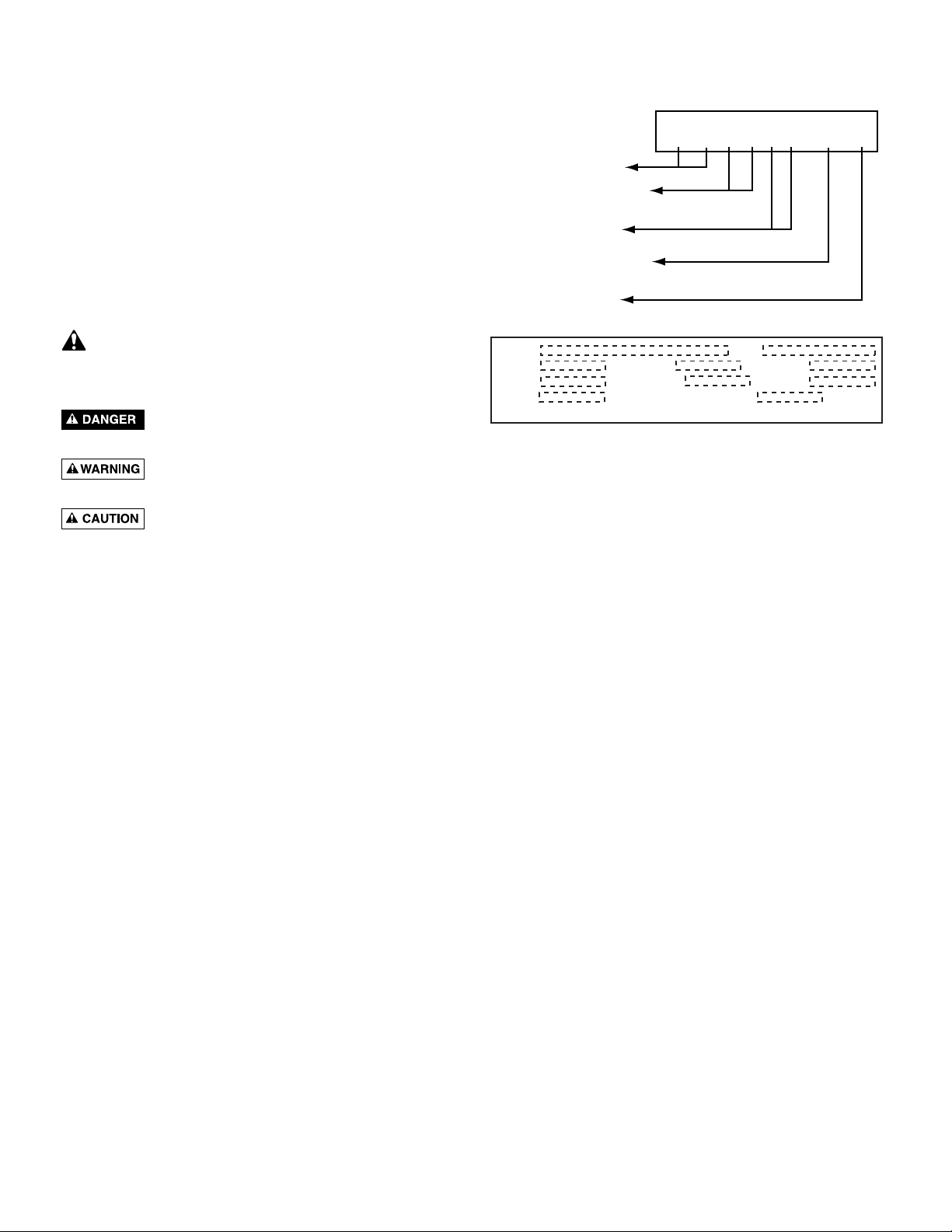
See the motor nameplate for electrical connection/wiring
diagram.
Taco pumps must be used with the proper size and type of
motor starter to ensure protection against damage from low
voltage, phase failure, current imbalances, and overloads.
The overload should be sized to trip at the full-load current
rating of the motor.
OPERATION
Priming
Hazardous pressure. Do not run the pump
with the discharge valve closed; the water in the pump may
boil, causing risk of explosion and steam burns to anyone
nearby.
Hazardous voltage. Disconnect all power to
the pump before servicing or working on the pump. Make
sure that the power is locked out and that the pump cannot
be accidentally started.
NOTICE: Under no circumstances should the pump be
operated without flow through the pump. Never operate
the pump dry.
Operation of closed systems or open systems with the
liquid level above the pump priming plug:
1. Close the discharge isolating valve and loosen the
needle valve in the vented priming plug in the pump
head (Figure 7). Do not remove the needle valve.
Risk of water damage and injury. Watch the
direction of the priming plug and make sure that the liquid
escaping from it does not injure persons nearby or damage
the motor or other components. In hot water installations,
pay particular attention to the risk of injury from scalding
hot water.
2. Slowly open the isolation valve in the suction pipe until
a steady stream of liquid runs out the vent in the priming
port.
3. Tighten the needle valve to 25 inch-pounds torque.
Completely open isolation valves.
NOTICE: Please turn to “Starting”, Page 7, before proceeding
any further.
Operation of open systems with the liquid level below the
top of the pump:
NOTICE: The suction pipe requires a check valve or
isolation valve.
1. Close the discharge isolation valve.
2. Remove the vented priming plug.
3. Pour liquid through the priming port until the suction
pipe and the pump are completely filled with liquid.
4. Replace the vented priming plug and tighten it securely.
5. Repeat steps 1-4 until the pump is primed.
NOTICE: Please turn to “Starting”, Page 7, before proceeding
any further.
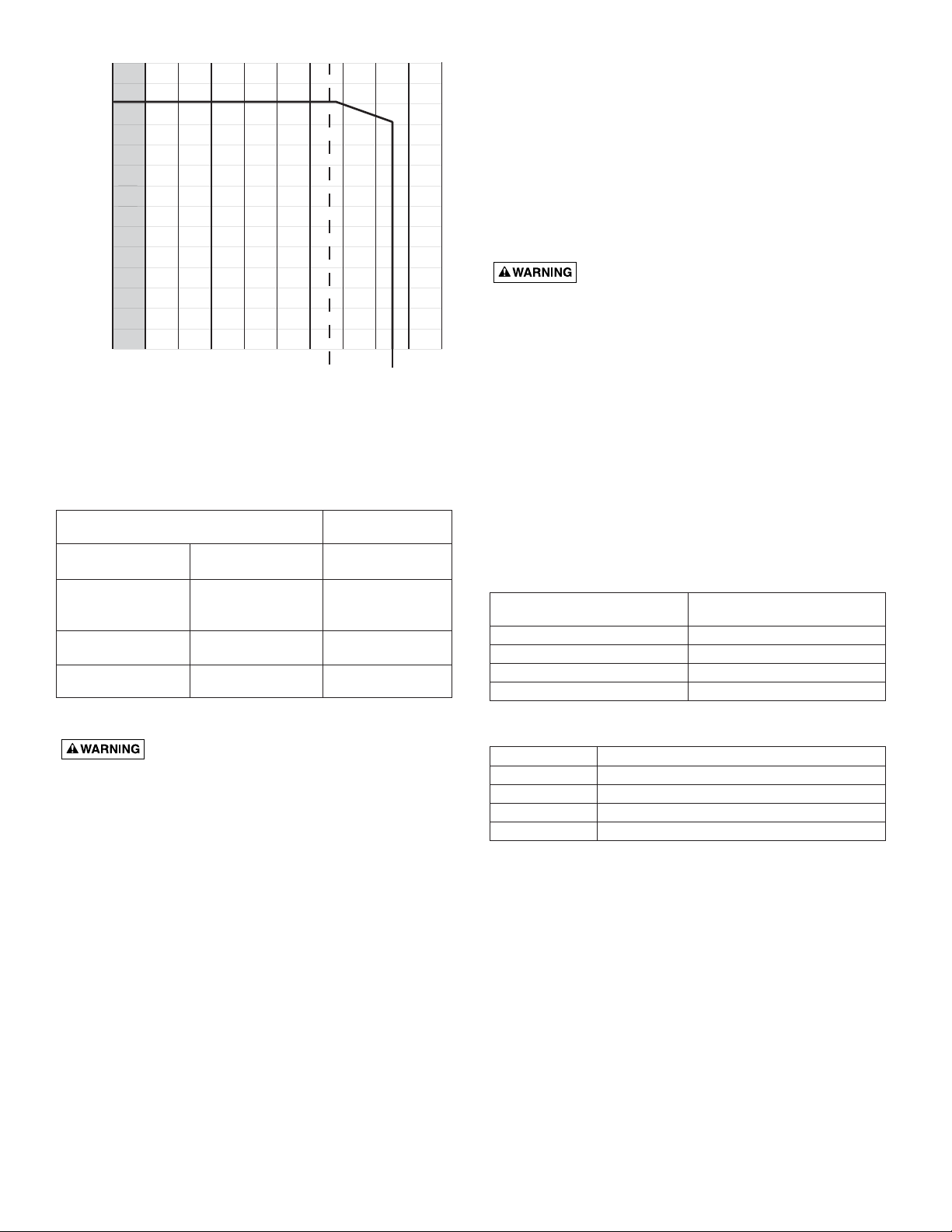
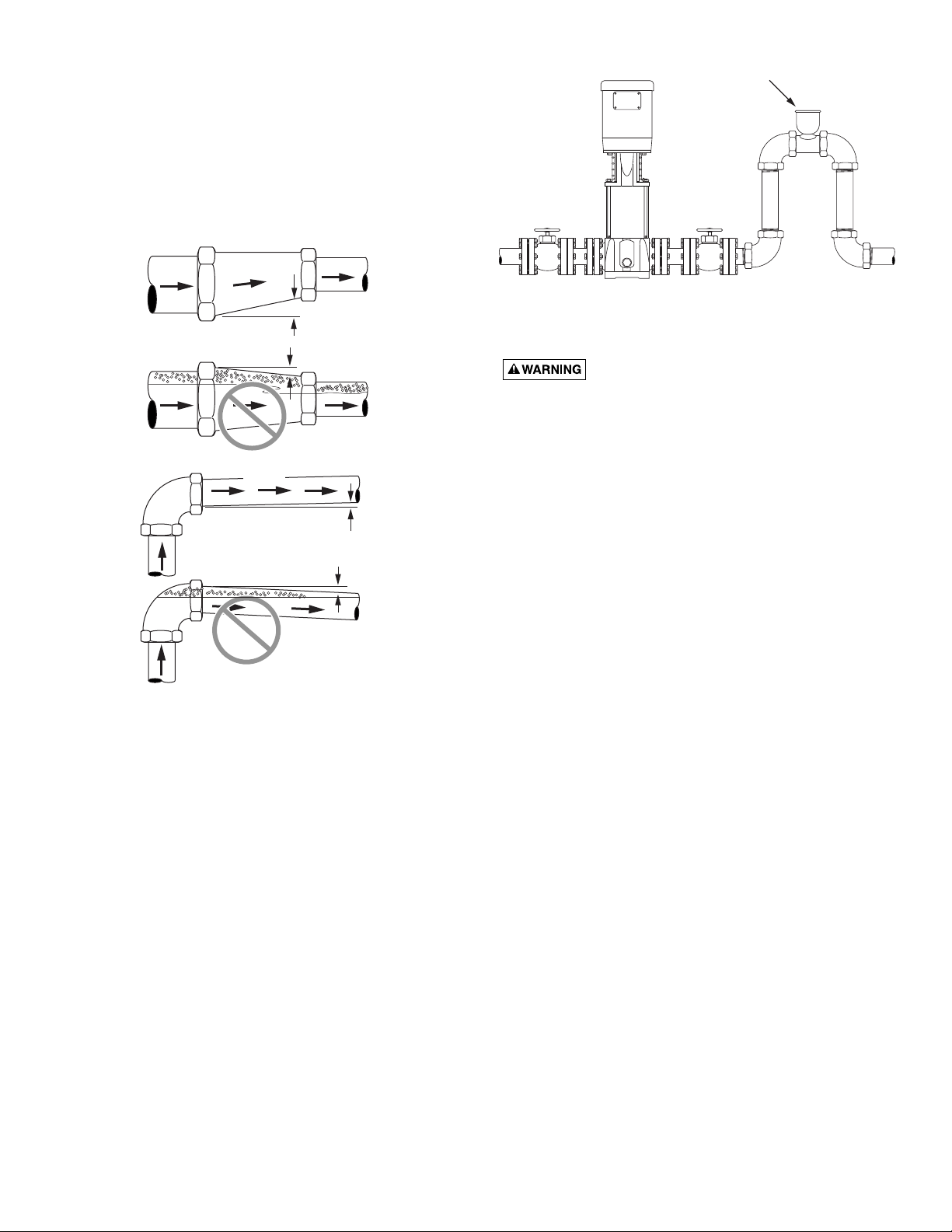
No-Flow Operation
This pump must not operate at no flow. To prevent no-flow
operation, install a bypass orifice, sized to allow the
minimum rate of flow to pass the pump at all times (see
Table III). Taco recommends a 3-inch long nipple-style
orifice, which will compensate for erosion and ensure the
correct minimum flow for extended time periods. Inspect
the orifice and bypass loop periodically to make sure that it
is not obstructed, eroded, or leaking and that the correct
minimum flow is maintained. See Table V to select the
correct orifice size for your installation.
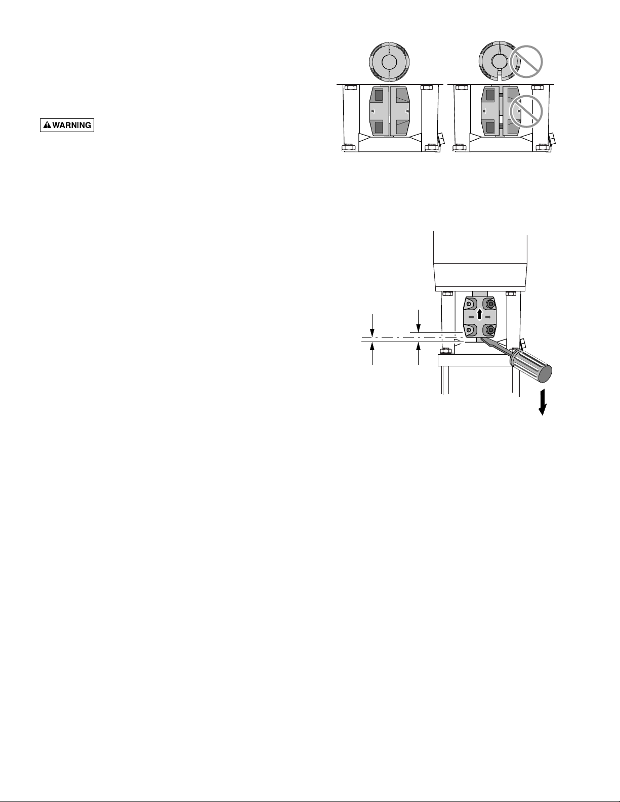
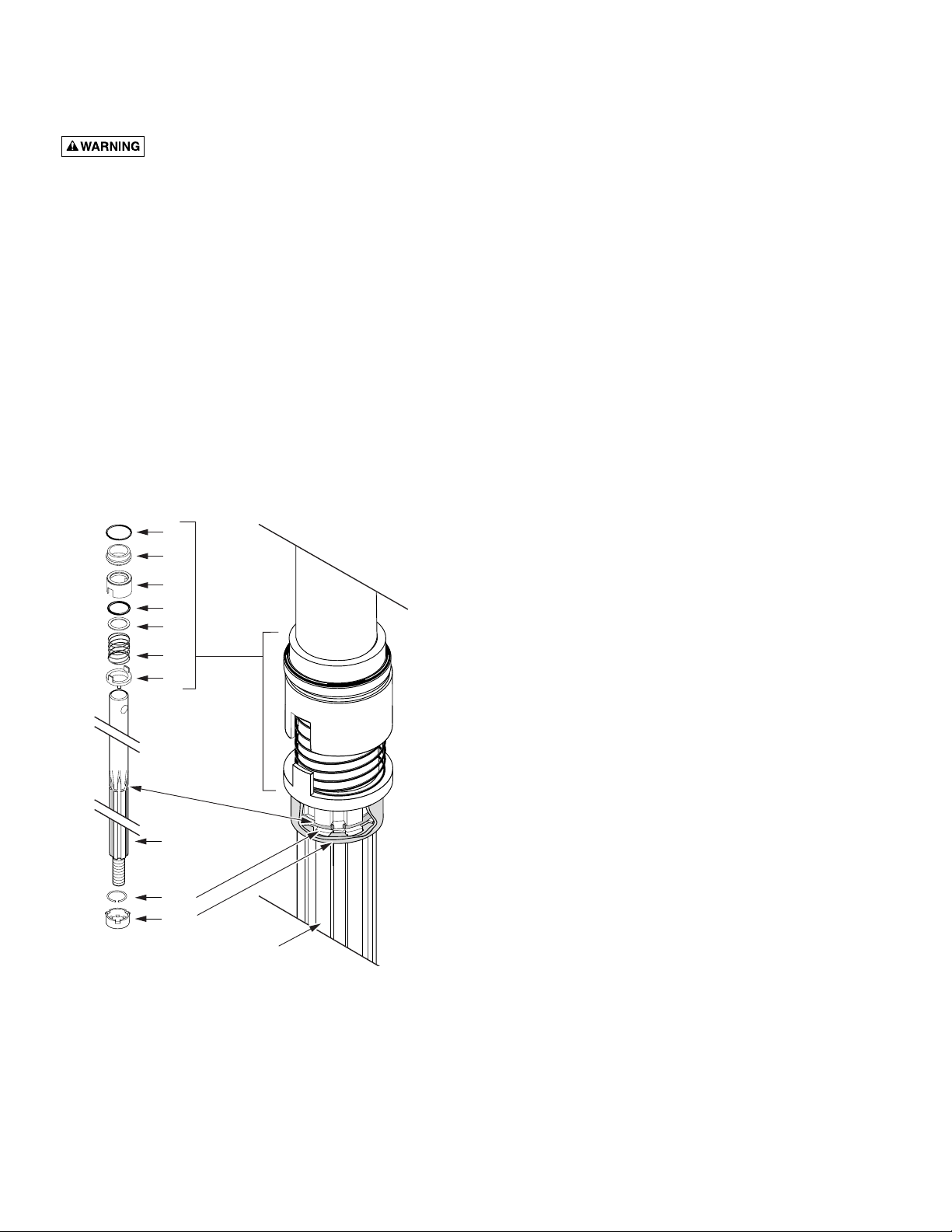
Checking Direction of Rotation
NOTICE: Do not disconnect the motor from the shaft to
check the direction of rotation. If you remove the coupling,
then you must adjust the shaft position when you reinstall
it. This must be done before starting the pump.
Arrows on the pump head show the correct direction of
rotation. When seen from the motor fan, the pump should
rotate
counterclockwise
()
.
For pump motors without a
fan remove one of the coupling guards and look at the
coupling to determine the direction of rotation. Turn off the
pump and replace coupling guard.
NOTICE: Do not check the direction of rotation until the
pump has been filled with liquid. See “Priming”, at left and
above.
1. Switch power off.
2. Remove the coupling guard and rotate the pump shaft to
be certain it can turn freely. Replace the coupling guard.
3. Verify that the electrical connections are in accordance
with the wiring diagram on the motor.
4. If the fan is visible, turn on and off to verify rotation.